Advertisement
Quick Links
Advertisement

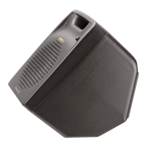
Summary of Contents for TC-Helicon VOICESOLO VSM-200
- Page 1 User’s Manual VSM-200 Active Voice Monitor...
- Page 3 IMPORTANT SAFETY INSTRUCTIONS The lightning flash with an arrowhead symbol within an The exclamation point within an equilateral triangle is equilateral triangle, is intended to alert the user to the intended to alert the user to the presence of important presence of uninsulated “dangerous voltage”...
- Page 4 These limits are designed to provide reasonable protection against harmful interference in residential installations. This VoiceSolo VSM-200 - Active Voice equipment generates, uses and can radiate radio frequency Monitor energy and, if not installed and used in accordance with the...
-
Page 5: Table Of Contents
Setup diagrams ....12 Specifications ....14 Specifications, interface, and features are subject to change without notice due to continued product improvement VoiceSolo VSM-200 Rev 1.01 English version... - Page 6 Enjoy! VSM-200 Features: The TC-Helicon Team • Quick mic stand set up. Integrates with Boom so the same stand is used for the monitor and microphone.
-
Page 7: Introduction
We've prioritized them below according to the speed at which you will access the help information. 1. Manual: The manual for VoiceSolo VSM-200 is a good source of application information and in depth answers for common questions. -
Page 8: Front Panel Diagram
FRONT PANEL DIAGRAM 1. CLIP led This led will light when the power amp is driven into limiting. Brief flashes now and then are OK. When the led is constantly lit however, you should lower the value of the Volume control. 2. -
Page 9: Back Panel Diagram
BACK PANEL DIAGRAM 1. MIC Pass Thru jack 4. Power switch Connecting an XLR cable here allows you to share your The | character represents power on, the O character mic or line input with another device, typically a mixer or represents power off. -
Page 10: Mic Stand Mounting Procedure
MIC STAND MOUNTING VoiceSolo Placement Options 1. Separate the boom from the stand by unscrewing the boom from the vertical shaft of the microphone stand. To VoiceSolo can be placed in 4 different ways. This versatility do this, tighten the clutch you use to raise and lower the allows you to use it as a mic stand mounted monitor one stand first. - Page 11 MIC STAND MOUNTING 3. Place VoiceSolo on the mic stand so the stand goes into the hole on the bottom of the VoiceSolo. If you don’t 5. Screw the Mic Boom Mount Attachment into your boom. need to mount VoiceSolo on a boom stand, you are finished with your setup.
- Page 12 MIC STAND MOUNTING 7. Your VoiceSolo should now look like this. 2. Still holding the boom so that it does not swing away, turn the lock nut counter-clockwise until it’s snug against the bottom of the boom. Note that it’s not possible to completely tighten the lock nut with your fingers, the final action is done by swinging the boom snug against the lock nut.
-
Page 13: Using Voicesolo
USING VOICESOLO Introduction Or plug in an instrument Connect a 1/4” cable between the LINE IN jack and your The following paragraphs should be read at least once to instrument. learn more about safe and successful use of VoiceSolo. Adjusting the volume Hooking up AC power Now raise the VOLUME level slowly while you sing or say “check”... -
Page 14: Setup Diagrams
In this application you will use a single monitor mix containing several input sources from a mixing console as the input to the VSM-200. This allows all performers to hear each other and this helps with vocal blending. In this setup, there is no “more me”... - Page 15 SETUP DIAGRAMS Fig. 3: VSM-200 Caution The VSM-200 accepts both microphone or line level signals on its inputs. NEVER SIMULTANEOUSLY PLUG A MICROPHONE AND A LINE LEVEL SIGNAL INTO THE VSM200. THE LINE LEVEL SIGNAL WILL BE CONNECTED DIRECTLY TO THE MICROPHONE MAKING ITS DIAPHRAGM VIBRATE LIKE A SPEAKER AND DAMAGE TO THE MICROPHONE MAY RESULT.
-
Page 16: Specifications
SPECIFICATIONS Audio Connections Parallel XLR and ¼-inch inputs with XLR Mic thru Power Amp 150 watts BASH® technology into 4 ohms (200 watts peak) Distortion: 0.5% @ 150W; 10% @ 200W Frequency response: 75 Hz – 20 kHz Input sensitivity 20 dBu to -40 dBu Speaker Speaker: 6.5 inch ICT custom-designed point source driver including inductively coupled tweeter...

Need help?
Do you have a question about the VOICESOLO VSM-200 and is the answer not in the manual?
Questions and answers