Table of Contents
Advertisement
Quick Links
Advertisement
Table of Contents

Related Manuals for Axel genius

Summary of Contents for Axel genius
- Page 1 Operating manual Rel 1.1 genius Broadcast Multifunction Switcher...
-
Page 2: Table Of Contents
ENGLISH CONTENTS INTRODUCTION ......................3 OPERATIVE PRINCIPLES ....................3 DECRIPTION........................6 3.1 FRONTAL PANEL....................6 3.2 BACK PANEL......................7 JUMPER SETTING AND FUNCTIONS ................8 4.1 INDEPENDENT, MASTER AND SLAVE.............8 4.2 EXTERNAL CONTROLS ..................9 4.3 EXPANDER BUS ....................9 4.4 AUDIO DETECTOR ..................10 4.5 LED 1/16 ......................10 4.6 MULTIPLAY ......................10... -
Page 3: Introduction
S/N ratio to assure disturb immunity even in difficult conditions while using long wires. EXPANDER BUS connector studied for cascade connection of several genius. Remote interface with optoisolated input and output controls and a section of relé... - Page 4 ENGLISH The B input features a ±10 dB amplifying section set through the potentiometer on the front panel, too. The frontal panel selector can select 3 operative modes with the following features: • AUTO: it allows remote control and the Auto Detector system can directly switch on B channel if audio is missing on A channel.
- Page 5 ENGLISH pag.5...
-
Page 6: Decription
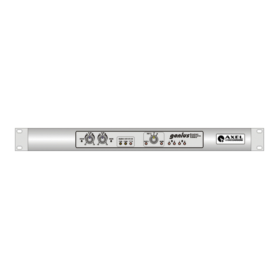
ENGLISH 3 DECRIPTION FRONTAL PANEL À GAIN A: Potentiometer setting the signal level on the A input, it controls ±10 dB. Á GAIN B: Potentiometer setting the signal level on the B input, it controls ±10 dB. Â Audio detector: device able to detect the white in the selected signal; it spots when the sound does not reach the set threshold (see THR). -
Page 7: Back Panel
ENGLISH Å Led A R: it shows the presence of right A input in the right OUT output. Æ Led B L: it shows the presence of left B input in the left OUT output. Ç Led B R: it shows the presence of right B input in the right OUT output. -
Page 8: Jumper Setting And Functions
ENGLISH Æ B IN: Left and Right inputs on connectors 3 pole XLR female connectors electronically balanced, PIN OUT standard configuration. Ç OUT DRAW: PIN RCA unbalanced output, it supplies the same signal present in B IN ; we suggest to use it as service output. -
Page 9: External Controls
ENGLISH (N.B. J5∩J6 shows that you must insert the jumper between a contact in the J5 position and a contact in the J6; J5+J6 shows that you need to insert 2 jumpers, one in J5 and another one in J6). -
Page 10: Audio Detector
ENGLISH AUDIO DETECTOR It sends the signal the Left channel of the A input to the Audio Detector adder . It sends the signal of the Right channel of the A input to the Audio Detector adder. It sends the signal of the Left channel of the B input to the Audio Detector adder. -
Page 11: Output Level
ENGLISH NOTE! Apart from closing Jumpers J10 e J12, to enable the 19 KHz tone when Input B is selected You need to establish again the R52 resistor which is located near IC 9 and behind the INPUT B – RIGHT XLR connector on the rear board. - Page 12 ENGLISH J7∩J8 A input Left channel INDEPENDENT It inserts the pre-emphasis in the signal of the Right channel in the B input. It inserts the pre-emphasis in the signal of the Left channel in the B input. It overlaps the 19 KHz to the –20dB to the signal of the Right channel of the B input.
-
Page 13: Remote Interface
ENGLISH 5 REMOTE INTERFACE genius Interface to connect the commands for the remote control of some functions of the to control equipment connected to it. Pin 1 manual error opto out (Emitter NPN optocopuler) Pin 2 manual error opto out (Common NPN optocopuler) -
Page 14: Installation And Connections
• We suggest to use high quality wires, well protected, and balanced connections. • We suggest to leave an empty space, at least a 19‘’ rack unit, between genius and any other equipment in order not to alterate the operative temperature. -
Page 15: Inputs
ENGLISH INPUTS genius features 2 balanced XLR female inputs active with 10KΩ input impedance, and 2 DRAW outputs on PIN RCA to withdraw the A and B input signals. The A input features a ±10 dB amplification section set using the potentiometer placed on the front panel. -
Page 16: Outputs
ENGLISH OUTPUTS genius features an XLR male balanced output active with 100Ω impedance and a DRAW output on PIN RCA for general purposes. The output features a +6 dB amplifying section controlled by jumper. We always recommend, when possible, to realise balanced connections with good quality wires. -
Page 17: Applications
ENGLISH 8 APPLICATIONS genius is a very flexible equipment and has many different application possibilities, according to its different settings. BI-CHANNEL SWITCHER Its use as bi-channel or double mono switcher equipment does not require any internal setting. EMERGENCY SWITCHER... -
Page 18: Technical Specifications
Do not open the equipment without being previously authorised by AXEL TECHNOLOGY, in case of seal breaking the warranty will expire. AXEL TECHNOLOGY will not be responsible for any damage, of any origin, caused or related to an incorrect use of the product. -
Page 19: Technical Documentation
ENGLISH 11 TECHNICAL DOCUMENTATION • Mother Board pag.19... - Page 20 ENGLISH pag.20...
- Page 21 ENGLISH • Front Panel pag.21...
Need help?
Do you have a question about the genius and is the answer not in the manual?
Questions and answers