
Related Manuals for Goldstar DH2510A


Summary of Contents for Goldstar DH2510A
- Page 1 Dehumidifier SERVICE MANUAL MODEL: DH2510A DH4010A DH5010A CAUTION - BEFORE SERVICING THE UNIT, READ THE SAFETY PRECAUTIONS IN THIS MANUAL. - ONLY FOR AUTHORIZED SERVICE.
-
Page 2: Table Of Contents
CONTENTS 1. PREFACE 1.1 SAFETY PRECAUTIONS ........................... 3 1.2 FEATURES ..............................3 1.3 DIMENSIONS ............................. 3 1.4 SPECIFICATIONS ............................4 1.5 CONTROL ..............................5 1.6 HOW TO OPERATE DEHUMIDIFIER ......................5 1.6.1 HOW DOES THE DEHUMIDIFIER WORK? ..................5 1.6.2 LOCATION FOR THE DEHUMIDIFIER ..................... 5 1.6.3 SWITCH ASSEMBLY, MICRO ...................... -
Page 3: Preface
1. PREFACE This Service Manual provides various service information, containing the mechanical and electrical parts etc. This dehumidifier was manufactured and assembled under the strict quality control system. The refrigerant is charged at the factory. Be sure to read the safety precaution prior to servicing the unit. 1.1 SAFETY PRECAUTIONS •... -
Page 4: Specifications
1.4 SPECIFICATIONS MODELS DH2510A DH4010A DH5010A ITEMS CAPACITY (Pint/Day) POWER SUPPLY (Phase, V, Hz) 1ø, 115V, 60Hz REFRIGERANT R134a REFRIGERANT CHARGE, oz(g) 4.4(125) 5.1(145) 7.2(204) CONTROL, DEFROST OPEN : 35.6˚F(3˚C – 3 CLOSE : 53.6˚F(13˚C – 3 HUMIDISTAT CONTROL RANGE : 20% ~ 80% RH NORMAL SETTING : 42 ±... -
Page 5: Control
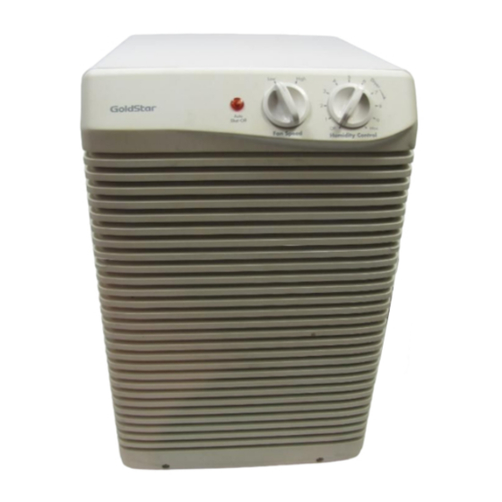
1.5 CONTROL Humidity Control • The Humidity Control can be set anywhere between High Off and Max for normal operation. If you need more dehumidification, turn the Humidity Control toward Max. If you need less dehumidification, turn the Humidity Control toward Off. Auto •... -
Page 6: Switch Assembly, Micro
Dryer NOTE: When dryer is replaced, proper injection to capillary is needed. On opening the dryer, it should be welded instantly. The oxidization of dryer inside and all tubes inside after welding can be prevented.(For Model DH2510A) Figure 4 —6—... -
Page 7: Circuit Diagram
2. CIRCUIT DIAGRAM • MODEL : DH2510A SWITCH, WH(BL) BK(BR) ROTARY BK(HI) RD(L) GR/YL BK(HI) RD(L) MOTOR OR(COM) TERMINAL BLOCK COMP. O.L.P. CONTROL, DEFROST WIRING DIAGRAM 3854A20015B PART NO. LOCATION Q'TY DESCRIPTION DH2510A PER SET MARKS 6411A20001K POWER CORD ASSEMBLY... - Page 8 • MODEL : DH4010A, DH5010A SWITCH, WH(BL) BK(BR) ROTARY BK(HI) RD(L) GR/YL BK(HI) RD(L) MOTOR OR(COM) TERMINAL BLOCK COMP. O.L.P. CONTROL, DEFROST WIRING DIAGRAM 3854A20015A PART NO. LOCATION Q'TY DESCRIPTION DH4010A DH5010A PER SET MARKS 6411A20001K POWER CORD ASSEMBLY 6600A20001A SWITCH, ROTARY 4681A20034A MOTOR ASSEMBLY SINGLE...
-
Page 9: Disassembly Instructions
3. DISASSEMBLY INSTRUCTIONS 3.1 MECHANICAL PARTS 3.1.1 BUCKET AND AIR FILTER 1. Disconnect the power supply. 2. Turn the Humidity Control off. 3. Remove the bucket (See Figure 5) 4. Flex the filter at the lower right corner and take it off. -
Page 10: Control Parts And Cycle Parts
3.2 CONTROL PARTS AND CYCLE PARTS 3.2.1 ROTARY SWITCH, HUMIDISAT AND NEON LAMP 1. Unfasten a screw located in the lower side of control box assy(DH2510A) then stretch control box like figure 9. Remove each screw located in the lower side of Control box assy and fastens Capacitor clamp then stretch Control box assy like figure 9. -
Page 11: Fan And Motor
3.2.6 FAN AND MOTOR 1. Remove 4 screws that fasten H/E assy. 2. Widen H/E assy 30 degree clockwise as like figure 13. 3. Remove one nut that fastens the fan 4. Unfasten 3 screws that secure the Motor. 5. Remove the Motor and Fan carefully in state of holding FAN as shown by the arrow. H/E assy means heat Exchange Assembly.) Figure 13 Figure 14... -
Page 12: Assembly Or Overload Protector (O.l.p.)
3. Disconnect the lead wire from the overload protector or P.T.C. assembly. 4. Remove the overload protector or P.T.C. assembly. (See Figure 16, 17) FOR DH2510A (Recipro Comp.) Figure 16 3.2.9 COMPRESSOR 1. Remove the cabinet. (Refer to section 3.1.3) 2. -
Page 13: Refrigerating Cycle
3.3 REFRIGERATING CYCLE 3.3.1 CONDENSER ASSEMBLY AND EVAPORATOR ASSEMBLY(HEAT EXCHANGE ASSEMBLY) 1. Remove the motor mount. (Refer to 3.2.3) 2. Pierce the pinch-off tube to discharge the refrigerant, using a FREON recovery system. 3. Remove the insulation on the H/E assembly 4. -
Page 14: How To Replace Refrigeration System
H/E assembly-system. If water quantity is over 150mg, it causes acid or corrosion in the cycle system and the capillary tube to be clogged by water and harmful materials. The model DH2510A must use dryer to prevent water from overflowing. —14—... - Page 15 Equipment needed: Vacuum pump, charging cylinder, manifold gauge, brazing equipment. pinch-off tool capable of making a vapor-proof seal, leak detector, tubing cutter, hand tools to remove components, service valve. EVAPORATOR ASSEMBLY EVAPORATOR ASSEMBLY (LOW PRESSURE SIDE) (LOW PRESSURE SIDE) CONDENSER ASSEMBLY CONDENSER ASSEMBLY (HIGH PRESSURE SIDE) (HIGH PRESSURE SIDE)
-
Page 16: Troubleshooting Guide
4. TROUBLESHOOTING GUIDE CONDITION CAUSE REMEDY The dehumidifier does not Check if humidistat is set to Set humidistat on a higher run. a low level. level. Check if bucket full lamp Empty the water in the is lit ON. bucket. Check circuit breaker. - Page 17 CONDITION CAUSE REMEDY 1. Dehumidifier does not operate. (Both No power Check power supply at outlet. compressor and fan motor do not Correct if none. operate.) Poor plug contact at outlet. Install plug properly or replace it. Bucket is full. If Auto Shut Off lights, empty the bucket.
- Page 18 CONDITION CAUSE REMEDY 5. Noisy operating If cracked, out of balance, or partially missing, replace it Foreign material plunged and rattle. Remove it. Tube hits frame. Adjust tubing routine carefully. Fan blade hits frame Check Motor Mount. If loose, tighten it. Internal compressor noise.
-
Page 19: Exploded View - Introduction
5. EXPLODED VIEW - INTRODUCTION OUTER CASE PARTS CONTROL PARTS CYCLE PARTS OUTER CASE PARTS —19—... - Page 20 • OUTER CASE PARTS AND CONTROL PARTS —20—...
- Page 21 • CYCLE PARTS AND CONTROL PARTS (MODEL: DH2510A) (MODEL: DH4010A/ DH5010A) —21—...
- Page 22 • CYCLE PARTS (ROTARY COMP.) (RECIPRO COMP.) MODEL: DH5010A MODEL: DH2510A DH4010A MODEL: DH2510A MODEL: DH4010A MODEL: DH5010A MODEL: DH5010A MODEL: DH4010A MODEL: DH2510A —22—...
-
Page 23: Replacement Parts List
6. REPLACEMENT PARTS LIST • MODEL: DH2510A Q'TY LOCATION PART NO. DESCRIPTION PERSET MARKS OUTER CASE PARTS AND CONTROL PARTS 6912A30001D LAMP, NEON 6600A20001A SWITCH, ROTARY 5216A20001A HUMIDISTAT 6640A40001A TERMINAL, BLOCK 4994A20011A CONTROL BOX, SINGLE 4941A30002A KNOB ASSEMBLY 3531A20012B GRILLE ASSEMBLY, FRONT... - Page 24 • MODEL: DH4010A Q'TY LOCATION PART NO. DESCRIPTION PERSET MARKS OUTER CASE PARTS AND CONTROL PARTS 6912A30001D LAMP, NEON 6600A20001A SWITCH, ROTARY 5216A20001A HUMIDISTAT 6120AR2194S CAPACITOR 4H00442G CLAMP, CAPACITOR 4994A20011A CONTROL BOX, SINGLE 4941A30002A KNOB ASSEMBLY 3531A20012A GRILLE ASSEMBLY, FRONT 6411A20001K POWER CORD ASSEMBLY 6600A30003A...
- Page 25 • MODEL: DH5010A Q'TY LOCATION PART NO. DESCRIPTION PERSET MARKS OUTER CASE PARTS AND CONTROL PARTS 6912A30001D LAMP, NEON 6600A20001A SWITCH, ROTARY 5216A20001A HUMIDISTAT 6120AR2194S CAPACITOR 4H00442G CLAMP, CAPACITOR 4994A20011A CONTROL BOX, SINGLE 4941A30002A KNOB ASSEMBLY 3531A20012A GRILLE ASSEMBLY, FRONT 6411A20001K POWER CORD ASSEMBLY 6600A30003A...
- Page 26 MEMO —26—...
- Page 27 MEMO —27—...
- Page 28 November, 1999 P/No : 3828A30039B Printed in Korea...
Need help?
Do you have a question about the DH2510A and is the answer not in the manual?
Questions and answers