Table of Contents
Advertisement
Quick Links
© 2013 Char-Broil, LLC Columbus, GA 31902
PRODUCT GUIDE
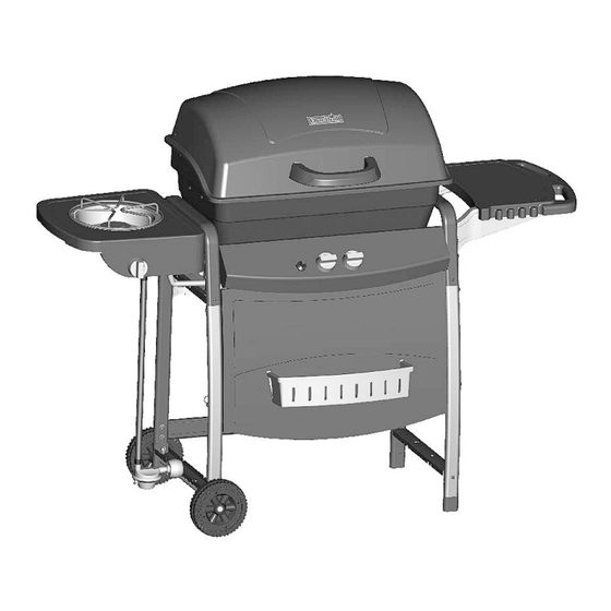
MODEL 463722713
C-23G3
IMPORTANT: Fill out the product record information below.
Serial Number
Date Purchased
For support and to register your
grill, please visit us at
www.charbroil.com
If you have questions or need
assistance during assembly,
please call 1-800-241-7548.
Printed in China
See rating label on grill for serial number.
Assembly instructions © 2013
09/28/12 • G305-001-390801
Advertisement
Table of Contents
Troubleshooting

Related Manuals for Char-Broil 463722713


Summary of Contents for Char-Broil 463722713
- Page 1 PRODUCT GUIDE MODEL 463722713 C-23G3 IMPORTANT: Fill out the product record information below. Serial Number See rating label on grill for serial number. Date Purchased For support and to register your grill, please visit us at www.charbroil.com If you have questions or need assistance during assembly, please call 1-800-241-7548.
-
Page 2: Table Of Contents
TABLE OF CONTENTS DANGER For Your Safety ........2-3 If you smell gas: Grilling Guide. -
Page 3: Grease Fires
WARNING CAUTION Using pots larger than 6 quarts in capacity could CALIFORNIA PROPOSITION 65 exceed weight limit of the 1. Combustible by-products produced when using side burner shelf this product contains chemicals known to the State or side shelf, of California to cause cancer, birth defects, or resulting in failure other reproductive harm. -
Page 4: Grilling Guide
Temperature - Convective Grills ONLY. GRILLING GUIDE – Getting Started The temperature gauge in the hood of your new grill measures air temperature. The air temperature inside your grill will never First Time Use be as hot as the temperature at the cooking surface. Read your Assembly Manual and ensure the grill is put together properly. - Page 5 Rotisserie Cooking GRILLING GUIDE – Grilling 101 Rotisserie cooking is best for 'round' meat, such as large roasts, whole poultry, and pork. It generally requires an accessory motor Outdoor grilling is really quite simple. You'll succeed with and spit rod that allows the meat to be turned at a constant burgers, dogs, or steaks usually on your very first try.
- Page 6 Wood Chips GRILLING GUIDE – Tips & Tricks For extra smoke flavor when grilling, try adding wood chips. Cooking on your new grill is a hands-on experience, and it is Soak the chips in water for approximately 30 minutes before recommended to remain outside with your grill while cooking.
- Page 7 Gear Trax Painted surfaces: Wash with mild detergent or non-abrasive accessories. Please visit charbroil.com for a complete list cleaner and warm water. Wipe dry with a soft non-abrasive cloth. of Gear Trax accessories. *Available on most models.
-
Page 8: Use And Care
LP Cylinder USE AND CARE •The LP cylinder used with your grill must meet the following requirements: DANGER •Use LP cylinders only with these required measurements: 12" (30.5cm) (diameter) x 18" (45.7 cm) (tall) with 20 lb. (9 kg.) capacity maximum. •... - Page 9 LP Cylinder Exchange Connecting Regulator to the LP Cylinder •Many retailers that sell grills offer you the option of replacing 1.LP cylinder must be properly secured onto grill. (Refer to your empty LP cylinder through an exchange service. Use only assembly section.) those reputable exchange companies that inspect, precision fill, 2.Turn all control knobs to the OFF position.
- Page 10 Leak Testing Valves, Hose and Regulator 1.Turn all grill control knobs to OFF. 2.Be sure regulator is tightly connected to LP cylinder. 3.Completely open LP cylinder valve by turning hand wheel counterclockwise. If you hear a rushing sound, turn gas off immediately.
- Page 11 Safety Tips WARNING ▲ Before opening LP cylinder valve, check the coupling nut for tightness. For Safe Use of Your Grill and to Avoid Serious ▲ When grill is not in use, turn off all control knobs and LP Injury: cylinder valve.
- Page 12 Sideburner Match Lighting Ignitor Lighting Turn ON gas at LP cylinder. ▲ Do not lean over grill while lighting. 2. Hold lit match to any port on the burner. Push in and turn Turn OFF gas burner control valves. sideburner knob to the HIGH position.
- Page 13 • Plated wire grates: Wash grates with concentrated grill Cleaning the Burner Assembly cleaner or use soap and water solution. Dry thoroughly and Follow these instructions to clean and/or replace parts of burner store indoors between cookouts. assembly or if you have trouble igniting grill. •...
-
Page 14: Limited Warranty
LIMITED WARRANTY This warranty only applies to units purchased from an authorized retailer. Manufacturer warrants to the original consumer-purchaser only that this product shall be free from defects in workmanship and materials after correct assembly and under normal and reasonable home use for the periods indicated below beginning on the date of purchase*. -
Page 15: Parts List
PARTS LIST Key Qty Description Key Qty Description FIREBOX ELECTRODE, F/ SB IGNITOR DRIP PAN BURNER WHEEL COLLECTOR/ ELECTRODE ASSY KNOB LOWER HINGE LOGO PLATE UPPER HINGE LEFT SIDE SHELF F/ SB HANDLE RIGHT SIDE SHELF GREASE CUP TANK RETAINER GREASE CUP CLIP MOUNTING BRACKET, F/ SIDE SHELF, (RF/LB) HEAT TENT... -
Page 16: Parts Diagram
PARTS DIAGRAM... -
Page 17: Assembly
ASSEMBLY Left leg Place upper leg as shown. NOTE: Left front and left back legs do not have leg extenders. In front, attach upper leg, side brace and left front leg (curve) with #10-24x1-1/4’’ machine screw and #10-24 flange nut. In back, attached the left back leg (straight) to upper leg. - Page 18 Front Panel Lay front legs down on the floor Slide front panel between legs. Attach with #10-24x2’’ machine screws and #10-24 flange nuts. Left leg assembly #10-24x2” #10-24 Machine Screw Flange Nut Qty. 4 Right leg assembly #10-24x2” Machine Screw Qty.
- Page 19 Hook tank exclusion wires onto front panel brackets, attach other end to back brace with #8x3/8" sheet metal screws #8x3/8’’ Sheet Metal Screw Qty. 3 Wheel Turn assembly upside down. Insert axle rod into wheel, legs and other wheel. Attach with a wheel bushing and hitch pin. Attach all in second hole. Hitch Pin Qty.
- Page 20 Control Panel and Firebox Supports Stand cart upright. In front, slide control panel between left and right legs, attach control panel with #10-24x2" machine screws. Place firebox supports onto screws and tighten with #10-24 flange nuts. Tighten all screws. In back, attach upper firebox support with #10-24x2" machine screws and #10-24 flange nuts. Chamfer edge Control Panel Firebox...
- Page 21 Heat Shield Attach heat shield with #10-24x1/2" machine screws and #10-24 flange nuts. Heat Shield #10-24X1/2” Machine Screw Qty. 2 #10-24 Flange Nut Qty. 2 Tank Retainer Insert tank retainer into side brace and secure with #10-24x3/8’’ wing screw. #10-24x3/8’’ Wing Screw Qty.
- Page 22 Burner and Firebox and Control Knobs Place burner assembly into firebox. Fasten the burner assembly to the firebox using 5x15 fiber washers #10- 24x1/2’’ machine screws . Insert two #10-24x1-1/4’’ machine screws from outer firebox, then fasten with two #10-24 flange nuts 5x15 fiber washers from inner.
- Page 23 Shelves Attach mounting brackets to right side shelf with side shelf bushing and #8x3/8’’ sheet metal screws (A). Insert mounting bracket into sideburner shelf support, secure with #10-24x1/2’’ machine screws (B). Attach mounting brackets to front of leg with 1/4-20x1/2’’ machine screws .
- Page 24 Sideburner Attach sideburner valve with #8x3/8’’ machine screws . Attach sideburner pan with #8x3/8’’ sheet metal screws 5x9 fiber washer (A). Place sideburner into shelf (B). Make sure valve is inside sideburner tube. Attach sideburner with a wing nut . Hook Sideburner clip to sideburner tube and around manifold.
- Page 25 Lower Hinges Attach lower hinges to back of firebox using #10-24x1/2’’ machine screws, 5x15 fiber washers and #10-24 flange nuts. The center flat portion of the hinge should be at the bottom (see inset). Lower Hinge #10-24x1/2” #10-24 5x15 Fiber Washer Machine Screw Flange Nut Qty.
- Page 26 Place lid assembly onto firebox, aligning hinges. Hinges on lid fit inside hinges on firebox. Secure using two hinge pins and hitch pins. Tighten upper hinge screws. NOTE: Tighten the hinges screws after installing the hinge pins. Hitch Pin Hinge Pin Qty.
- Page 27 Swing Away Insert ends of Swing Away pivot wire into holes in sides of grill lid. Insert ends of Swing Away leg wire into holes in sides of firebox. NOTE: Pivot and leg wires, running side-to-side, Swing Away should be under wires running front-to-back. If Pivot Wire pivot and leg wires are on top, swing away is installed upside-down.
-
Page 28: Troubleshooting
DANGER: If a gas leak cannot be stopped, or a fire occurs due to gas leakage, call the fire department. Emergencies Possible Cause Prevention/Solution Gas leaking from •Damaged hose. •Turn off gas at LP cylinder or at source on natural gas systems. If cracked/cut/burned anything but burned, replace valve/hose/regulator. -
Page 29: Troubleshooting
Troubleshooting (continued) Problem Possible Cause Prevention/Solution Burner(s) will not light PIEZO PUSH-BUTTON AND ROTARY: using ignitor. •Push-button sticks at bottom. •Replace ignitor. •Rotary knob rotates without clicking. •Replace knob. •Sparking between ignitor and electrode. •Inspect wire insulation and proper connection. Replace wires if insulation is broken. - Page 30 NOTES...
Need help?
Do you have a question about the 463722713 and is the answer not in the manual?
Questions and answers