Kenwood TM-271A Service Manual
Vhf fm transceiver
Hide thumbs
Also See for TM-271A:
- Instruction manual (60 pages) ,
- Instruction manual (80 pages) ,
- Service manual (4 pages)
Table of Contents
Advertisement
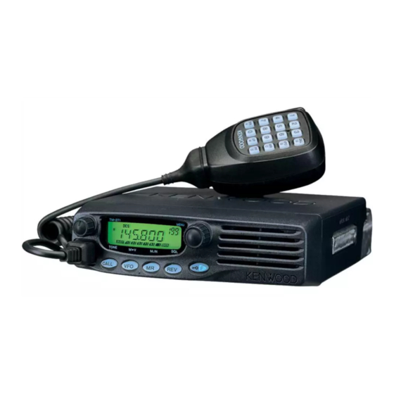
VHF FM TRANSCEIVER
TM-271A/271E
SERVICE MANUAL
TM-271A (M2,M4)
TM-271A/E (K,M3,E)
CIRCUIT DESCRIPTION ............................ 2
SEMICONDUCTOR DATA ........................ 8
COMPONENTS DESCRIPTION ................ 9
PARTS LIST ............................................. 10
EXPLODED VIEW .................................... 17
PACKING ................................................. 18
RESETTING THE TRANSCEIVER ........... 19
ADJUSTMENT ........................................ 20
Key top
(K29-9291-01)
Knob (Volume)
(K29-9292-03)
Key top
(K29-9291-01)
Knob (Volume)
(K29-9292-03)
CONTENTS
© 2003-10 PRINTED IN JAPAN
B51-8663-00 ( N ) 743
TERMINAL FUNCTION ........................... 27
PC BOARD
DISPLAY UNIT (X54-3450-10) ............ 28
TX-RX UNIT (X57-685X-XX) ............... 30
SCHEMATIC DIAGRAM .......................... 34
BLOCK DIAGRAM ................................... 38
LEVEL DIAGRAM .................................... 40
SPECIFICATION ................... BACK COVER
Microphone
(T91-0624-05)
Cabinet
(A01-2193-01)
Knob (Encoder)
(K29-9293-03)
Panel assy
(A62-1088-03)
Microphone
(T91-0641-05)
Cabinet
(A01-2193-01)
Knob (Encoder)
(K29-9293-03)
Panel assy
(A62-1088-03)
Advertisement
Table of Contents

Related Manuals for Kenwood TM-271A


Summary of Contents for Kenwood TM-271A
-
Page 1: Table Of Contents
VHF FM TRANSCEIVER TM-271A/271E SERVICE MANUAL © 2003-10 PRINTED IN JAPAN B51-8663-00 ( N ) 743 TM-271A (M2,M4) Key top (K29-9291-01) Microphone (T91-0624-05) Knob (Volume) (K29-9292-03) Cabinet (A01-2193-01) Knob (Encoder) (K29-9293-03) Panel assy (A62-1088-03) TM-271A/E (K,M3,E) Key top (K29-9291-01) Microphone... -
Page 2: Circuit Description
TM-271A/271E CIRCUIT DESCRIPTION ■ IF Amplifier Frequency Configuration The first IF signal is amplified by Q351, and then goes to The receiver utilizes double conversion. The first IF is IC301 (FM processing IC). The signal is heterodyned again 49.95MHz and the second IF is 450kHz. The first local oscil- with a second local oscillator signal within IC301 to create a lator signal is supplied from the PLL circuit. - Page 3 TM-271A/271E CIRCUIT DESCRIPTION ■ Wide/Narrow Switching Circuit ■ Squelch Circuit The Wide port (pin 65) and Narrow port (pin 64) of the CPU The detection output from the FM IF IC (IC301) passes is used to switch between ceramic filters. When the Wide through a noise amplifier (Q301) to detect noise.
- Page 4 TM-271A/271E CIRCUIT DESCRIPTION ■ Unlock Circuit Transmitter System During reception, the 8RC signal goes high, the 8TC signal ■ Outline goes low, and Q34 turns on. Q33 turns on and a voltage is The transmitter circuit produces and amplifies the desired applied to 8R.
-
Page 5: Control Circuit
TM-271A/271E CIRCUIT DESCRIPTION ■ Key Matrix Circuit Control Circuit The TM-271 front panel has function keys. Each of them The CPU carries out the following tasks (See Fig. 10.): is connected to a cross point of a matrix of the KI1 to KI3 and 1) Controls the WIDE, NARROW, TX/RX outputs. - Page 6 TM-271A/271E CIRCUIT DESCRIPTION ■ Decode • CTCSS/DCS The signal (W/NO (EVOL2)) goes to DTMF IN (pin 95) of CPU (IC101). The CTCSS/DCS signal will pass through the low-pass filters in the CPU (IC101) and be decoded within the CPU (IC101). The DTMF signal will be decoded within the CPU (IC101).
- Page 7 TM-271A/271E CIRCUIT DESCRIPTION ■ Transmission Signals PR1 is the 1200bps data communications reception out- put. It outputs the FM detection circuit output through an AF Transmission modulation signals enter from PKD of the filter (IC251). Output is controlled with the mute switch data terminal (CN2).
-
Page 8: Semiconductor Data
TM-271A/271E SEMICONDUCTOR DATA Microprocessor : 30622MAA-B85GP (TX-RX Unit IC101) ■ Terminal Function Pin No. Name Function Pin No. Name Function TONE CTCSS/DCS/Clone output Common data DTMF DTMF/BEEP/1750Hz output Common clock PLLE PLL IC chip select DST1 Destination 1 GND. 57~59... -
Page 9: Components Description
TM-271A/271E COMPONENTS DESCRIPTION Display Unit (X54-3450-10) Ref. No. Parts name Description Ref. No. Parts name Description Q302 Transistor Buffer amplifier / 16.8MHz 3rd over tone LCD controller Q351 Transistor IF amplifier Transistor DC switch Q352 Mixer Transistor LCD backlit switch... -
Page 10: Parts List
MIC HOLDER ACCESSORY R47,48 RK73GB1J473J CHIP R 1/16W J29-0662-03 BRACKET ACCESSORY R49,50 RK73FB2A560J CHIP R 1/10W R51-53 R92-1252-05 CHIP R 0 OHM J 1/16W ✽ K29-9291-01 KEY TOP ✽ K29-9292-03 KNOB (VOLUME) RK73FB2A560J CHIP R 1/10W K,M2,M3,M4 : TM-271A : TM-271E... - Page 11 CK73GB1H102K CHIP C 1000PF C307 CK73GB1E223K CHIP C 0.022UF C205 CK73GB1C104K CHIP C 0.10UF C206 CK73GB1H102K CHIP C 1000PF K,M2,M3 C308 CK73GB1H102K CHIP C 1000PF C206 CK73GB1H102K CHIP C 1000PF C309 CK73GB1E223K CHIP C 0.022UF K,M2,M3,M4 : TM-271A : TM-271E...
- Page 12 C531 C92-0719-05 CHIP-TAN 47UF 25WV C533 C93-0572-05 CHIP C 100PF C421,422 CK73GB1H471K CHIP C 470PF C423 C92-0555-05 CHIP-TAN 0.047UF 35WV C536 CK73FB1H102K CHIP C 1000PF C424 C92-0004-05 CHIP-TAN 1.0UF 16WV C541,542 CM73F2H120J CHIP C 12PF K,M2,M3,M4 : TM-271A : TM-271E...
- Page 13 0 OHM J 1/16W M2,M3,M4 L413 L40-4778-67 SMALL FIXED INDUCTOR (47NH) R124-127 RK73GB1J473J CHIP R 1/16W R151 RK73GB1J103J CHIP R 1/16W L414,415 L40-2702-86 SMALL FIXED INDUCTOR (27UH) R152 RK73GB1J472J CHIP R 4.7K 1/16W L416,417 L92-0443-05 FERRITE CHIP K,M2,M3,M4 : TM-271A : TM-271E...
- Page 14 1.0K 1/16W R404 RK73GB1J103J CHIP R 1/16W R266 RK73GB1J562J CHIP R 5.6K 1/16W R268 RK73GB1J102J CHIP R 1.0K 1/16W R406 RK73GB1J103J CHIP R 1/16W R269 RK73GB1J393J CHIP R 1/16W R407 RK73GB1J152J CHIP R 1.5K 1/16W K,M2,M3,M4 : TM-271A : TM-271E...
- Page 15 CHIP R 1/2W KRC102S DIGITAL TRANSISTOR R527 RK73GB1J224J CHIP R 220K 1/16W KRC404RTK DIGITAL TRANSISTOR R528,529 RK73GB1J471J CHIP R 1/16W R530 RK73GB1J102J CHIP R 1.0K 1/16W Q86,87 2SK1830 R531 RK73GB1J473J CHIP R 1/16W Q201 2SC4919 TRANSISTOR K,M2,M3,M4 : TM-271A : TM-271E...
- Page 16 Q405,406 2SK508NV(K52) Q407 2SJ347 Q408 KRX102U TRANSISTOR Q410 2SC5108(Y) TRANSISTOR Q411 2SC4649(N,P) TRANSISTOR Q440 2SC2412K TRANSISTOR Q501,502 2SC3357 TRANSISTOR Q503 PD55003TR DRIVE FET Q504 RD70HVF1-01 FINAL FET ✽ TH97,98 NCP18WF104J03 THERMISTOR ✽ TH301 NCP18WF104J03 THERMISTOR K,M2,M3,M4 : TM-271A : TM-271E...
-
Page 17: Exploded View
TM-271A/271E EXPLODED VIEW A M2.6 x 8 : N67-2608-46 M2 x 10 BLK : N80-2010-45 M2.6 x 6 (Br-Tap) : N87-2606-46 D M2.6 x 14 (Br-Tap) : N87-2614-46 Display unit 13,14 IC252 Cx12 Q504 TX-RX unit Standard label Sticker : M3 S/No. -
Page 18: Packing
TM-271A/271E PACKING 5 Instruction manual (B62-1738-10) : K,M2,M3,E (B62-1739-10) : K,M2,E (B62-1745-10) : M3 (B62-1746-10) : M4 (B62-1784-10) : E 704 Pamphlet 705 Warranty card 33 Packing fixture (H12-3112-05) 36 Protection bag (H25-2341-04) 36 Protection bag (H25-2341-04) 50 Microphone (T91-0641-05) : K,M3,E... -
Page 19: Resetting Tansceiver
TM-271A/271E RESETTING THE TRANSCEIVER ■ VFO Reset Resetting the Tansceiver This resets the transceiver parameters excluding the If your transceiver seems to be malfunctioning, resetting DTMF Memory, the Memory channel contents, and the Call the microprocessor may solve the problem. The following 2 channel contents. -
Page 20: Adjustment
TM-271A/271E ADJUSTMENT q Blinks in Adjustment Mode. Adjustment Mode w Adjustment item display In Adjustment Mode, the transceiver can adjusted using e Adjustment value display. Can be adjusted while it is its panel keys. “blinking”. Displayed as a hexadecimal number from 00 to FF. - Page 21 TM-271A/271E ADJUSTMENT Adjustment Item Adjustment On the Note Transmit Receive Signalling Frequency Point Display (MHz) (MHz) Frequency Tune Center 155.10 155.05 TX High Power “H” icon appear 136.10 136.05 Low’ 142.10 142.05 Center 150.10 150.05 High’ 156.10 156.05 High 173.90 173.95...
-
Page 22: Test Equipment Required For Alignment
TM-271A/271E ADJUSTMENT Test Equipment Required for Alignment Test Equipment Major Specifications 1. Standard Signal Generator Frequency Range 136 to 175MHz (SSG) Modulation Frequency modulation and external modulation Output –127dBm/0.1µV to greater than –7dBm/100mV 2. Power Meter Input Impedance 50Ω Operation Frequency... - Page 23 TM-271A/271E ADJUSTMENT • Speaker Cable Adjustment Location The speaker cable should be formed before mounting the ■ Adjustment Points shield cover as below. TX-RX unit Component side F501 Speaker Q504 Q503 cable R524 R518 TEMP1 TEMP2 R516 Locator VR601 CNVSS...
- Page 24 TM-271A/271E ADJUSTMENT PCB Section Measurement Adjustment Specifications/ Item Condition Remarks Test equipment Terminal Parts Method 1. Setting 1) Power supply voltage DC Power supply terminal : 13.8V ± 0.2V 2. VCO lock 1) CH : TX high Digital voltmeter TC402 5.5V...
-
Page 25: Receiver Section
Oscilloscope 3) Transmit AF V.M ± 1.2~1.9kHz 7. MIC 1) CH : TX center (Narrow) Check sensitivity 2) AG : 1kHz/5.4mV (TM-271A) (Narrow) AG : 1kHz/2.4mV (TM-271E) 3) Transmit Encoder ± 0.75kHz (Wide) ± 50Hz 8. CTCSS 1) CH : TX low (Wide) Modulation analyzer ±... - Page 26 TM-271A/271E ADJUSTMENT Measurement Adjustment Specifications/ Item Condition Test equipment Terminal Parts Method Remarks 2. Squelch 1) CH : RX low (Wide) Encoder Adjust to open the squelch tight CH : RX center (Wide/Narrow) Oscilloscope EXT. SP knob CH : RX high (Wide) AF V.M...
-
Page 27: Terminal Function
TM-271A/271E TERMINAL FUNCTION TX-RX UNIT (X57-685X-XX) CN No. Pin No. Name Function CN No. Pin No. Name Function ENC A Encoder A INT SP Internal speaker Microphone Key Check Ground ENC B Encoder B MIC KEY Microphone Key Data Out from LCD... - Page 28 TM-271A/271E PC BOARD DISPLAY UNIT (X54-3450-10) Component side view (J72-0905-09) POWER/VOL HOOK MIC JACK CALL DISPLAY UNIT (X54-3450-10) Foil side view (J72-0905-09) HOOK...
- Page 29 TM-271A/271E PC BOARD DISPLAY UNIT (X54-3450-10) Component side view (J72-0905-09) Ref. No. Address ENCODER FUNCTION Component side Layer 1 Layer 2 J72-0905-09 Foil side DISPLAY UNIT (X54-3450-10) Foil side view (J72-0905-09) Ref. No. Address ENCA ENCB MIC KEY POWER Component side...
- Page 30 TM-271A/271E TM-271A/271E PC BOARD PC BOARD DISPLAY UNIT (X54-3450-10) Component side view (J72-0905-09) DISPLAY UNIT (X54-3450-10) Component side view (J72-0905-09) Ref. No. Address POWER/VOL ENCODER HOOK MIC JACK FUNCTION Component side CALL Layer 1 Layer 2 J72-0905-09 Foil side DISPLAY UNIT (X54-3450-10) Foil side view (J72-0905-09) DISPLAY UNIT (X54-3450-10) Foil side view (J72-0905-09) Ref.
- Page 31 TM-271A/271E PC BOARD TX-RX UNIT (X57-685X-XX) Component side view (J72-0906-09) 0-10 : TM-271A (K) 0-21 : TM-271A (M2) 0-22 : TM-271A (M3) 0-23 : TM-271A (M4) 2-71 : TM-271E (E) EXT. SP C527 C528 C530 C529 C533 Q503 C536 R518...
- Page 32 TM-271A/271E PC BOARD TX-RX UNIT (X57-685X-XX) Component side view (J72-0906-09) 0-10 : TM-271A (K) 0-21 : TM-271A (M2) 0-22 : TM-271A (M3) 0-23 : TM-271A (M4) 2-71 : TM-271E (E) Ref. No. Address IC33 IC161 IC201 IC202 C574 IC203 C615...
- Page 33 TX-RX UNIT (X57-685X-XX) Component side view (J72-0906-09) TX-RX UNIT (X57-685X-XX) Component side view (J72-0906-09) 0-10 : TM-271A (K) 0-21 : TM-271A (M2) 0-22 : TM-271A (M3) 0-10 : TM-271A (K) 0-21 : TM-271A (M2) 0-22 : TM-271A (M3) 0-23 : TM-271A (M4) 2-71 : TM-271E (E) 0-23 : TM-271A (M4) 2-71 : TM-271E (E) Ref.
- Page 34 TM-271A/271E PC BOARD TX-RX UNIT (X57-685X-XX) Foil side view (J72-0906-09) 0-10 : TM-271A (K) 0-21 : TM-271A (M2) 0-22 : TM-271A (M3) 0-23 : TM-271A (M4) 2-71 : TM-271E (E) R800 L605 C616 C610 R601 D607 C607 C606 L603 D606...
- Page 35 TM-271A/271E PC BOARD TX-RX UNIT (X57-685X-XX) Foil side view (J72-0906-09) 0-10 : TM-271A (K) 0-21 : TM-271A (M2) 0-22 : TM-271A (M3) 0-23 : TM-271A (M4) 2-71 : TM-271E (E) Ref. No. Address IC31 IC32 IC34 IC35 IC66 IC101 IC251...
- Page 36 TX-RX UNIT (X57-685X-XX) Foil side view (J72-0906-09) TX-RX UNIT (X57-685X-XX) Foil side view (J72-0906-09) 0-10 : TM-271A (K) 0-21 : TM-271A (M2) 0-22 : TM-271A (M3) 0-10 : TM-271A (K) 0-21 : TM-271A (M2) 0-22 : TM-271A (M3) 0-23 : TM-271A (M4) 2-71 : TM-271E (E) 0-23 : TM-271A (M4) 2-71 : TM-271E (E) Ref.
-
Page 37: Schematic Diagram
TM-271A/271E SCHEMATIC DIAGRAM TX-RX UNIT (X57-685X-XX) R414 Q402,403 R:0.74V BUFFER AMP CHARGE PUMP RX VCO T:0.62V D403,404 C430 4.5p Q410 D402 R410 RX VCO R:6.11V R:0.97V 2SC5108(Y) Q405 Q402 R:6.17V 8.2k L406 C426 HZU5ALL R418 R419 R421 L405 D404 L408... - Page 38 TM-271A/271E SCHEMATIC DIAGRAM TX-RX UNIT (X57-685X-XX R:5V RF AMP/ RF AMP/ DRIVE STAGE DRIVE STAGE Q501 Q502 R:4.84V RF SWITCH RF AMP 2SC3357 2SC3357 T:5.61V T:1.23V T:1.26V T:5.73V C515 R516 C516 L503 L504 R:7.42V D409 DAN235E Q411 820p C502 R503...
- Page 39 TM-271A/271E SCHEMATIC DIAGRAM TX-RX UNIT (X57-685X-XX R800 F501 R:13.8V T:13.45V C526 680p R522 C623 FINAL AMP Q504 ANT SW RD70HVF1-01 D602 C533 L507 L508 C554 MA4PH633 C603 L602 L603 L604 100p 2.5T 1000p 1000p Q503 PD55003TR T:1.46V DRIVE AMP T:1.6V T:1.45V...
- Page 40 TM-271A/271E SCHEMATIC DIAGRAM DISPLAY UNIT (X54-3450-10) LCD (B38-0885-05) CALL MHz & MENU ADJUASTMENT W02-3665-05 Func ENCODER 0.1u 1SS355 SEG27 SEG26 MBL(Key A) SEG25 4.96V SEG24 ON/OFF & VOLUME SEG23 ADJUASTMENT HOOK SEG22 4.94V SEG20 LCD CONTROLLER R31-0646-05 SEG20 PT6554LQ VDD1...
- Page 41 0.022u 750k C312 0.1u KRC102S C213 DEC2 FLAMPI IC201 R124 R314 2.2k AF MUTE 0-21 0.027u 1000p 0.022u 750k N:5V TM-271A 144-148MHz R207 NJM2100V 3300p PH_S RSSI R215 R214 W:0V R315 0-22 0.027u 1000p 0.022u 750k Q201 MIC AMP/ QUCO...
-
Page 42: Block Diagram
TM-271A/271E BLOCK DIAGRAM DISPLAY UNIT (X54-3450-10) TX-RX UNIT (X57-685X-XX) Q404 2SC4649(N,P) MIC KEY 2SK50 R31-0649-05 Q402 VIARIABLE RESISTOR POWER IC401 PTT(TXD) CHARGE 2SA1832(GR) MB15A02 PUMP PLLE HOOK(RXD) LOOP Q407 PLL IC CM(MIC KEY2) FILTER 2SJ347 16.8MHz CHARGE Q403 CALL PUMP 16.8MHz... - Page 43 TM-271A/271E BLOCK DIAGRAM D602 Q411 MA4PH633 Q502 Q503 Q504 IC402 2SC4649 Q501 Q410 D603,605 Q405 2SC3357 PD55003 RD70HVF1 UPB1509GV (N,P) 2SC5108(Y) 2SC3357 XB15A709 2SK508NV(K52) DRIVE FINAL DRIVE BUFF DIVIDER ANT SW Q408 D409 Q407 KRX102U DAN235E 2SJ347 POW. POW. D606...
-
Page 44: Level Diagram
TM-271A/271E LEVEL DIAGRAM Receiver Section Center Frequency 49.95MHz 450kHz W : –77.6dBm N : –74.2dBm W : –124.0dBm W : –119.5dBm W : –104.7dBm W : –103.9dBm W : –112.3dBm W : –92.1dBm /CF2 N : –123.5dBm N : –119.0dBm N : –103.7dBm... - Page 45 TM-271A/271E LEVEL DIAGRAM 450kHz Audio Frequency W : –85.0dBm N : –84.5dBm /CF2 0.33Vrms 0.32Vrms 0.26Vrms 0.30Vrms 0.31Vrms 10mVrms 0.50Vrms 0.64Vrms IC301 IC251 IC251 IC251 IC251 IC161 IC252 Q251 vel meter. 12dB SINAD.) To make measurements in the AF section, connect the AC level meter.
-
Page 46: Specification
Leuvensesteenweg 248 J, 1800 Vilvoorde, Belgium KENWOOD ELECTRONICS FRANCE S.A. 13, Boulevard Ney, 75018 Paris, France KENWOOD ELECTRONICS U.K. LIMITED KENWOOD House, Dwight Road, Watford, Herts., WD18 9EB United Kingdom KENWOOD ELECTRONICS EUROPE B.V. Amsterdamseweg 37, 1422 AC Uithoorn, The Netherlands KENWOOD ELECTRONICS ITALIA S.p.A.
Need help?
Do you have a question about the TM-271A and is the answer not in the manual?
Questions and answers