Table of Contents
Advertisement
Advertisement
Table of Contents

Related Manuals for MSI X58A-GD45 series


Summary of Contents for MSI X58A-GD45 series
- Page 1 X58A-GD45 series MS-7522 (v5.x) Mainboard G52-75221XE...
-
Page 2: Trademarks
Alternatively, please try the following help resources for further guidance. ◙ Visit the MSI website for FAQ, technical guide, BIOS updates, driver updates, and other information: http://www.msi.com/index.php?func=service ◙ Contact our technical staff at: http://ocss.msi.com... -
Page 3: Safety Instructions
MS-7522 MS-7522 Safety Instructions ■ Always read the safety instructions carefully. ■ Keep this User’s Manual for future reference. ■ Keep this equipment away from humidity. ■ Lay this equipment on a reliable flat surface before setting it up. ■ The openings on the enclosure are for air convection hence protects the equipment from overheating. -
Page 4: Fcc-B Radio Frequency Interference Statement
Preface Preface FCC-B Radio Frequency Interference Statement This equipment has been tested and found to comply with the limits for a Class B digi- tal device, pursuant to Part 15 of the FCC Rules. These limits are designed to provide reasonable protection against harmful inter- ference in a residential installation. -
Page 5: Weee (Waste Electrical And Electronic Equipment) Statement
MSI will comply with the product take back requirements at the end of life of MSI-branded prod- ucts that are sold into the EU. - Page 6 MSI će poštovati zahtev o preuzimanju ovakvih proizvoda kojima je istekao vek trajanja, koji imaju MSI oznaku i koji su prodati u EU. Ove proiz- vode možete vratiti na lokalnim mestima za prikupljanje.
- Page 7 MSI si adeguerà a tale Direttiva ritirando tutti i prodotti marchiati MSI che sono stati venduti all’interno dell’Unione Europea alla fine del loro...
-
Page 8: Table Of Contents
Preface Preface Contents Copyright Notice .................... ii Trademarks ....................ii Revision History..................... ii Technical Support..................ii Safety Instructions ..................iii FCC-B Radio Frequency Interference Statement.......... iv WEEE (Waste Electrical and Electronic Equipment) Statement ....v Chapter 1 Getting Started................1-1 Mainboard Specifications ..................1-2 Mainboard Layout .................... - Page 9 MS-7522 MS-7522 Appendix A Realtek Audio ................A-1 Installing the Realtek HD Audio Driver ..............A-2 Software Configuration ..................A-3 Hardware Default Setting ..................A-5 Appendix B Intel RAID ................B-1 Introduction ......................B-2 BIOS Configuration ....................B-3 Installing Driver ....................B-10 Degraded RAID Array ..................B-12 Appendix C Marvell RAID ................
-
Page 11: Chapter 1 Getting Started
Chapter 1 Getting Started Thank you for choosing the X58A-GD45 Series (MS- 7522 v5.X) ATX mainboard. The X58A-GD45 Series mainboards are based on Intel X58 & ICH10R chipsets ® for optimal system efficiency. Designed to fit the ad- vanced Intel LGA1366 processor, the X58A-GD45 Se- ®... -
Page 12: Mainboard Specifications
Getting Started Mainboard Specifications Processor Support ■ Intel i7 processor in the LGA1366 package ® (For the latest information about CPU, please visit http://www.msi.com/index. php?func=cpuform2) ■ Up to 6.4 GT/s Chipset ■ North Bridge : Intel X58 chipset ® ■... - Page 13 Form Factor ■ ATX (24.4cm X 30.5 cm) Mounting ■ 9 mounting holes * If you need to purchase accessories and request the part numbers, you could search the product web page and find details on our web address below http://www.msi.com/index.php...
-
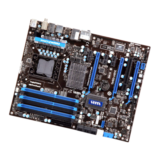
Page 14: Mainboard Layout
Intel T:RS-Out M:CS-Out B:SS-Out PCI _E1 PCI _E2 Intel ICH10R PCI _E3 JBAT1 PCI _E4 PCI _E5 SATA9 PCI 1 JTPM1 PCI _E6 RESET JFP2 JCOM1 JFP1 JAUD1 JCD1 SYSFAN4 J1394_1 JUSB2 JUSB1 POWER1 RESET1 X58A-GD45 Series (MS-7522 v5.X) Mainboard... -
Page 15: Packing Checklist
MS-7522 Packing Checklist MSI Driver/Utility DVD MSI mainboard SATA Cable (Optional) USB 3.0 Bracket User’s Guide Power Cable (Optional) Back IO Shield * The pictures are for reference only and may vary from the packing contents of the product you purchased. -
Page 17: Chapter 2 Hardware Setup
Chapter 2 Hardware Setup This chapter provides you with the information about hardware setup procedures. While doing the installa- tion, be careful in holding the components and follow the installation procedures. For some components, if you install in the wrong orientation, the components will not work properly. -
Page 18: Quick Components Guide
Hardware Setup Hardware Setup Quick Components Guide DDR3, p.2-8 JPWR3, p.2-11 CPU, p.2-4 CPUFAN, p.2-15 Back Panel, p.2-12 JPWR1, p.2-11 SYSFAN, p.2-15 PCIE, p.2-22 SATA, p.2-14 SYSFAN, p.2-15 JUSB3, p.2-16 PCI, p.2-22 JCI1, p.2-19 JSP1, p.2-17 JTPM1, p.2-18 JBAT1, p.2-20 RESET JAUD1, p.2-19 JCOM1, p.2-15... -
Page 19: Screw Holes
MS-7522 MS-7522 Screw Holes When you install the mainboard, you have to place the mainboard into the chassis in the correct direction. The locations of screws holes on the mainboard are shown as below. The side has to toward the rear, the position for the I/O shield of the chassis. -
Page 20: Cpu (Central Processing Unit)
When you are installing the CPU, make sure to install the cooler to prevent overheating. If you do not have the CPU cooler, consult your dealer before turning on the computer. For the latest information about CPU, please visit http://www.msi.com/index. php?func=cpuform2... -
Page 21: Cpu & Cooler Installation
MS-7522 MS-7522 CPU & Cooler Installation When you are installing the CPU, make sure the CPU has a cooler attached on the top to prevent overheating. Meanwhile, do not forget to apply some thermal paste on CPU before installing the heat sink/cooler fan for better heat dispersion. Follow the steps below to install the CPU &... - Page 22 Hardware Setup Hardware Setup Visually inspect if the CPU is seated Cover the load plate onto the pack- well into the socket. If not, take out age. the CPU with pure vertical motion and reinstall. Press down the load lever lightly onto Align the holes on the mainboard with the load plate, and then secure the the heatsink.
- Page 23 MS-7522 MS-7522 Press the four hooks down to fasten Turn over the mainboard to confirm the cooler. that the clip-ends are correctly in- serted. Mainboard Hook Finally, attach the CPU Fan cable to the CPU fan connector on the main- board.
-
Page 24: Memory
Hardware Setup Hardware Setup Memory These DIMM slots are used for installing memory modules. For more information on compatible components, please visit http://www.msi.com/index.php?func=testreport DDR3 240-pin, 1.5V 48x2=96 pin 72x2=144 pin Memory Population Rule Please refer to the following illustrations for memory population rules. - Page 25 MS-7522 MS-7522 Triple-Channel mode Population Rule In Triple-Channel mode, the memory modules can transmit and receive data with three data bus lines simultaneously. Enabling Triple-Channel mode can enhance the best system performance. When you have three or more memory modules, please always insert them as the figures shown in below.
-
Page 26: Installing Memory Modules
Hardware Setup Hardware Setup To enable successful system boot-up, always insert the memory modules into the • DIMM_1 first. • Due to the chipset resource deployment, the system density will only be detected up to 23+GB (not full 24GB) when each DIMM is installed with a 4GB memory module. Installing Memory Modules The memory module has only one notch on the center and will only fit in the right orientation. -
Page 27: Power Supply
MS-7522 MS-7522 Power Supply ATX 24-pin Power Connector: JPWR1 This connector allows you to connect an ATX 24-pin power supply. To connect the ATX 24-pin power supply, make sure the plug of the power supply is inserted in the proper orientation and the pins are aligned. -
Page 28: Back Panel
Hardware Setup Hardware Setup Back Panel Coaxial S/PDIF-Out Clear CMOS Button Mouse 1394 Port USB 2.0 Port RS-Out Line-In CS-Out Line-Out Keyboard USB 2.0 Port eSATA Port USB 2.0 Port SS-Out Optical S/PDIF-Out ▶ Mouse/Keyboard The standard PS/2 mouse/keyboard DIN connector is for a PS/2 mouse/keyboard. - Page 29 MS-7522 MS-7522 ▶ eSATA Port The eSATA (External SATA) port is for attaching the eSATA hard drive. ▶ The standard RJ-45 LAN jack is for connection to Yellow Green/ Orange the Local Area Network (LAN). You can connect a network cable to it. Color LED State Condition...
-
Page 30: Connectors
Hardware Setup Hardware Setup Connectors Serial ATA Connector: SATA1~9 This connector is a high-speed Serial ATA interface port. Each connector can connect to one Serial ATA device. * The MB layout in this figure is for reference only. SATA1~6 (3Gb/s) supported by Intel ICH10R ®... - Page 31 MS-7522 MS-7522 Fan Power Connectors: CPUFAN,SYSFAN1~5 The fan power connectors support system cooling fan with +12V. When connecting the wire to the connectors, always note that the red wire is the positive and should be con- nected to the +12V; the black wire is Ground and should be connected to GND. If the mainboard has a System Hardware Monitor chipset on-board, you must use a specially designed fan with speed sensor to take advantage of the CPU fan control.
- Page 32 Hardware Setup Hardware Setup Front USB Connector: JUSB1, JUSB2 This connector, compliant with Intel I/O Connectivity Design Guide, is ideal for con- ® necting high-speed USB interface peripherals such as USB HDD, digital cameras, MP3 players, printers, modems and the like. * The MB layout in this figure is for reference only.
- Page 33 MS-7522 MS-7522 IEEE1394 Connector: J1394_1 This connector allows you to connect the IEEE1394 device via an optional IEEE1394 bracket. * The MB layout in this figure is for reference only. 1394 Bracket (optional) S/PDIF-Out Connector: JSP1 This connector is used to connect S/PDIF (Sony & Philips Digital Interconnect Format) interface for digital audio transmission.
- Page 34 Hardware Setup Hardware Setup Front Panel Connectors: JFP1, JFP2 These connectors are for electrical connection to the front panel switches and LEDs. The JFP1 is compliant with Intel Front Panel I/O Connectivity Design Guide. ® JFP2 JFP1 TPM Module connector: JTPM1 This connector connects to a TPM (Trusted Platform Module) module (optional).
- Page 35 MS-7522 MS-7522 Front Panel Audio Connector: JAUD1 This connector allows you to connect the front panel audio and is compliant with Intel ® Front Panel I/O Connectivity Design Guide. Chassis Intrusion Connector: JCI1 This connector connects to the chassis intrusion switch cable. If the chassis is opened, the chassis intrusion mechanism will be activated.
-
Page 36: Jumpers
Hardware Setup Hardware Setup Jumpers Clear CMOS Jumper: JBAT1 There is a CMOS RAM on board with an external battery power supply to preserve the system configuration data. With the CMOS RAM, the system can automatically boot OS every time it is turned on. If you want to clear the system configuration, set the jumper to clear data. -
Page 37: Buttons
MS-7522 MS-7522 Buttons The mainboard provides the following buttons for you to set the computer’s function. This section will explain how to change your mainboard’s function through the use of button. Power Button This button is used to turn-on or turn-off the system. Press the button to turn-on or turn-off the system. -
Page 38: Slots
Hardware Setup Hardware Setup Slots PCIE (Peripheral Component Interconnect Express) Slot The PCIE slot supports the PCIE interface expansion card. PCIE x16 Slot PCIE x1 Slot PCI (Peripheral Component Interconnect) Slot The PCI slot supports LAN card, SCSI card, USB card, and other add-on cards that comply with PCI specifications. -
Page 39: Led Status Indicators
MS-7522 MS-7522 LED Status Indicators APS LEDs HDD LED Standby LED RESET APS LEDs These APS (Active Phase Switching) LEDs indicate the current CPU power phase mode. Follow the instructions below to read. : Lights : Off CPU is in 1 phase power mode. CPU is in 2 phase power mode. -
Page 40: Standby Led
Hardware Setup HDD LED Lights red when the hard drive is operating. Standby LED Lights orange when the system is in standby (S4/S5 ) status. 2-24... -
Page 41: Chapter 3 Bios Setup
Chapter 3 BIOS Setup This chapter provides information on the BIOS Setup program and allows you to configure the system for op- timum use. You may need to run the Setup program when: ■ An error message appears on the screen during the system booting up, and requests you to run SETUP. -
Page 42: Entering Setup
BIOS Setup BIOS Setup Entering Setup Power on the computer and the system will start POST (Power On Self Test) process. When the message below appears on the screen, press <DEL> key to enter Setup. Press DEL to enter SETUP If the message disappears before you respond and you still wish to enter Setup, restart the system by turning it OFF and On or pressing the RESET button. -
Page 43: Control Keys
MS-7522 MS-7522 Control Keys <↑> Move to the previous item <↓> Move to the next item <←> Move to the item in the left hand <→> Move to the item in the right hand <Enter> Select the item <Esc> Jumps to the Exit menu or returns to the main menu from a submenu <+/PU>... -
Page 44: The Main Menu
BIOS Setup BIOS Setup The Main Menu ▶ Standard CMOS Features Use this menu for basic system configurations, such as time, date etc. ▶ Advanced BIOS Features Use this menu to setup the items of the BIOS special enhanced features. ▶... - Page 45 MS-7522 MS-7522 ▶ M-Flash Use this menu to read/ flash the BIOS from storage drive (FAT/ FAT32 format only). ▶ Overclocking Profile Use this menu to save/ load your settings to/ from CMOS for BIOS. ▶ Load Fail-Safe Defaults Use this menu to load the default values set by the BIOS vendor for stable system performance.
-
Page 46: Standard Cmos Features
BIOS Setup BIOS Setup Standard CMOS Features The items in Standard CMOS Features Menu include some basic setup items. Use the arrow keys to highlight the item and then use the <PgUp> or <PgDn> keys to select the value you want in each item. ▶... - Page 47 MS-7522 MS-7522 ▶ SATA1~6/ SATA9/ E-SATA1 Press <Enter> to enter the sub-menu and the following screen appears: ▶ Device / Vendor / Size It will show the device information that you connected to the SATA connector. Important SATA1~6, SATA9 & E-SATA1 are appearing when you connect the HD devices to the SATA connectors on the mainboard.
-
Page 48: Advanced Bios Features
BIOS Setup BIOS Setup Advanced BIOS Features ▶ Boot Sequence Press <Enter> to enter the sub-menu. ▶ 1st/ 2nd/ 3rd/ --- Boot Device These items allow you to set the first/ second/ third boot device where BIOS at- tempts to load the disk operating system. ▶... - Page 49 MS-7522 MS-7522 ▶ Quick Booting Setting the item to [Enabled] allows the system to boot within 10 seconds since it will skip some check items. ▶ Boot Up Num-Lock LED This setting is to set the Num Lock status when the system is powered on. Setting to [On] will turn on the Num Lock key when the system is powered on.
-
Page 50: Integrated Peripherals
BIOS Setup BIOS Setup Integrated Peripherals ▶ USB Controller This setting allows you to enable/disable the onboard USB controller. ▶ USB Device Legacy Support Select [Enabled] if you need to use a USB-interfaced device in the operating system. ▶ Onboard LAN Controller This setting allows you to enable/disable the onboard LAN controller. - Page 51 MS-7522 MS-7522 ▶ On-Chip ATA Devices Press <Enter> to enter the sub-menu and the following screen appears: ▶ PCI IDE BusMaster This item allows you to enable/ disable BIOS to used PCI busmastering for reading/ writing to IDE drives. ▶ On-Chip SATA Controller This item allows users to enable or disable the on-chip SATA controller.
-
Page 52: Power Management Setup
BIOS Setup BIOS Setup Power Management Setup Important S3-related functions described in this section are available only when the BIOS sup- ports S3 sleep mode. ▶ ACPI Function This item is to activate the ACPI (Advanced Configuration and Power Management Interface) Function. - Page 53 MS-7522 MS-7522 ▶ Restore On AC Power Loss This item specifies whether your system will reboot after a power failure or interrupt occurs. Settings are: [Off] Always leaves the computer in the power off state. [On] Always leaves the computer in the power on state. [Last State] Restore the system to the status before power failure or interrupt occurred.
-
Page 54: H/W Monitor
BIOS Setup BIOS Setup H/W Monitor ▶ Chassis Intrusion The field enables or disables the feature of recording the chassis intrusion status and issuing a warning message if the chassis is once opened. To clear the warning mes- sage, set the field to [Reset]. The setting of the field will automatically return to [Enabled] later. -
Page 55: Green Power
MS-7522 MS-7522 Green Power ▶ CPU Phase Control When set to [Auto], the hardware will auto adjust the CPU power phase according to the loading of CPU to reach the best power saving function. ▶ Motherboard LED Control This item is used to turn on (Auto)/ turn off (Disabled) the power phase LEDs of the mainboard. -
Page 56: Bios Setting Password
BIOS Setup BIOS Setup BIOS Setting Password When you select this function, a message as below will appear on the screen: ▶ U-Key This item is used to enable/ disable USB driver device as a key. ▶ Make U-Key at This item appears when U-Key is set to Enabled, it can be used to specify the USB driver device as a key. - Page 57 MS-7522 MS-7522 your system configuration. About Supervisor Password & User Password: Supervisor password: Can enter and change the settings of the setup menu. User password: Can only enter but do not have the right to change the settings of the setup menu.
-
Page 58: Cell Menu
BIOS Setup BIOS Setup Cell Menu Important Change these settings only if you are familiar with the chipset. ▶ Current CPU / DRAM / QPI Frequency These items show the current frequencies of CPU, Memory and QPI. Read-only. 3-18... - Page 59 MS-7522 MS-7522 ▶ CPU Specifications Press <Enter> to enter the sub-menu and the following screen appears. This submenu shows the information of installed CPU. ▶ CPU Technology Support Press <Enter> to enter the sub-menu. In this sub-menu, it shows the installed CPU technologies.
- Page 60 BIOS Setup BIOS Setup support Enhanced Halt state (C1E). ▶ Overspeed Protection Overspeed Protection function can monitor the current CPU draws as well as its power consumption. If it exceeds a certain level, the processor automatically reduces its clock speed. If you want to overclock your CPU, set it to [Disabled]. ▶...
- Page 61 MS-7522 MS-7522 ▶ C1E Support To enable this item to read the CPU power consumption while idle. Not all processors support Enhanced Halt state (C1E). ▶ Intel Turbo Boost This item will appear when you install a CPU with Intel Turbo Boost technology. This item is used to enable/ disable Intel Turbo Boost technology.
- Page 62 BIOS Setup BIOS Setup ▶ Adjusted CPU Frequency (MHz) It shows the adjusted CPU frequency. Read-only. ▶ MEMORY-Z Press <Enter> to enter the sub-menu and the following screen appears. ▶ DIMM1~6 Memory SPD Information Press <Enter> to enter the sub-menu. The sub-menu displays the informations of installed memory.
- Page 63 MS-7522 MS-7522 ▶ CH1/ CH2/ CH3 tRAS This setting determines the time RAS takes to read from and write to memory cell. ▶ CH1/ CH2/ CH3 tRFC This setting determines the time RFC takes to read from and write to a memory cell.
- Page 64 BIOS Setup BIOS Setup ▶ CPU Amplitude Control/ PCI Express Amplitude Control These items are used to select the CPU/ PCI Express clock amplitude. ▶ CPU CLK Skew/ MCH CLK Skew These items are used to select the CPU/ MCH chipset clock skew. They can help CPU to reach the higher overclocking performance.
- Page 65 MS-7522 MS-7522 Important Failed Overclocking Resolution This mainboard supports overclocking greatly. However, please make sure your pe- ripherals and components are bearable for some special settings. Any operation that exceeds product specification is not recommended. Any risk or damge resulting from improper operation will not be under our product warranty.
-
Page 66: M-Flash
BIOS Setup BIOS Setup M-Flash == BIOS Update or Boot 2nd BIOS From USB drive== ▶ M-Flash function as M-Flash function allows you to flash BIOS from USB drive/ storage drive (FAT/ FAT32 format only), or allows the system to boot from the BIOS file inside USB drive (FAT/ FAT32 format only). - Page 67 MS-7522 MS-7522 Important • Please refer to the block diagram below about the M-Flash function. • Due to the special design of some graphics cards will cause dark screen during M- flash operation, and you may refer the beeps from the system to confirm the current M-flash process.
- Page 68 BIOS Setup BIOS Setup ▶ Load BIOS source File from When the M-Flash function as sets to [BIOS Update], this item is selectable. Use this item to select particular BIOS file from the USB/ Storage (FAT/32 format only) drive. ▶ Boot 2nd BIOS from USB Drive When the M-Flash function as sets to [Boot] ], this item is selectable.
-
Page 69: Overclocking Profile
MS-7522 MS-7522 Overclocking Profile ▶ Overclocking Profile 1/ 2/ 3/ 4/ 5/ 6 These items are used to save the current settings to selected profile, and they are also used to load the settings from the selected profile. ▶ OC Retry Count When overclocking has failed, setting this item to [3,5] will allow system to reboot 3/ 5 times with the same overclocked configuration. -
Page 70: Load Fail-Safe/ Optimized Defaults
BIOS Setup Load Fail-Safe/ Optimized Defaults The two options on the main menu allow users to restore all of the BIOS settings to the default Fail-Safe or Optimized values. The Optimized Defaults are the default values set by the mainboard manufacturer specifically for optimal performance of the mainboard. The Fail-Safe Defaults are the default values set by the BIOS vendor for stable system performance. -
Page 71: Appendix A Realtek Audio
Appendix A Realtek Audio The Realtek audio provides 10-channel DAC that simul- taneously supports 7.1 sound playback and 2 channels of independent stereo sound output (multiple streaming) through the Front-Out-Left and Front-Out-Right chan- nels. -
Page 72: Installing The Realtek Hd Audio Driver
Realtek Audio Realtek Audio Installing the Realtek HD Audio Driver You need to install the HD audio driver for Realtek audio codec to function properly before you can get access to 2-, 4-, 6-, 8- channel or 7.1+2 channel audio operations. Follow the procedures described below to install the drivers for different operating sys- tems. -
Page 73: Software Configuration
MS-7522 MS-7522 Software Configuration After installing the audio driver, the “Realtek HD Audio Manager” icon will appear at the notification area (lower right of the screen). You may double click the icon and the GUI will pop up accordingly. It is also available to enable the audio driver by clicking the Realtek HD Audio Manager from the Control Panel. -
Page 74: Auto Popup Dialog
Realtek Audio Realtek Audio ■ Device Selection Here you can select a audio output source to change the related options. the “check” sign (in orange) indicates the devices as default. ■ Volume Adjustment You can control the volume or balance the right/left side of the speakers that you plugged in front or rear panel by adjust the bar. -
Page 75: Hardware Default Setting
MS-7522 MS-7522 Hardware Default Setting The following diagrams are audio back panel default setting. ■ Backpanel audio jacks to 2-channel speakers diagram F r o ■ Backpanel audio jacks to 4-channel speakers diagram F r o R e a... - Page 76 Realtek Audio ■ Backpanel audio jacks to 6-channel speakers diagram F r o C e n R e a t e r & S u b w o o f ■ Backpanel audio jacks to 8-channel speakers diagram F r o C e n R e a t e r...
-
Page 77: Appendix B Intel Raid
Appendix B Intel RAID This appendix will assist users in configuring and en- abling RAID functionality on platforms... -
Page 78: Introduction
Intel RAID Intel RAID Introduction The mainboard comes with the Intel RAID controller that allows you to configure SATA hard drives as RAID sets. SATA hard drives deliver blistering transfer speeds up to 3 Gb/s. Serial ATA uses long, thin cables, making it easier to connect your drive and improving the airflow inside your PC. -
Page 79: Bios Configuration
MS-7522 MS-7522 BIOS Configuration The Intel Matrix Storage Manager Option ROM should be integrated with the system BIOS on all motherboards with a supported Intel chipset. The Intel Matrix Stroage Man- ager Option ROM is the Intel RAID implementation and provides BIOS and DOS disk services. - Page 80 Intel RAID Intel RAID After pressing the <Ctrl> and <I> keys simultaneously, the following window will ap- pear: ■ Create RAID Volume Select option 1 Create RAID Volume” and press <Enter> key. The following screen appears. Then in the Name field, specify a RAID Volume name and then press the <TAB>...
- Page 81 MS-7522 MS-7522 In the Disk field, press <Enter> key and the following screen appears. Use <Space> key to select the disks you want to create for the RAID volume, then click <Enter> key to finish selection. Then select the strip value for the RAID array by using the “upper arrow” or “down arrow”...
- Page 82 Intel RAID Intel RAID Important Since you want to create two volumes (Intel Matrix RAID Technology), this default size (maximum) needs to be reduced. Type in a new size for the first volume. As an ex- ample: if you want the first volume to span the first half of the two disks, re-type the size to be half of what is shown by default.
- Page 83 MS-7522 MS-7522 ■ Delete RAID Volume Here you can delete the RAID volume, but please be noted that all data on RAID drives will be lost. Important If your system currently boots to RAID and you delete the RAID volume in the Intel RAID Option ROM, your system will become unbootable.
- Page 84 Intel RAID Intel RAID ■ Reset Disks to Non-RAID Select option 3 Reset Disks to Non-RAID and press <Enter> to delete the RAID volume and remove any RAID structures from the drives. The following screen appears: Press <Y> key to accept the selection. Important •...
- Page 85 MS-7522 MS-7522 ■ Recovery Volume Options Select option 4 Recovery Volume Options and press <Enter> to change recovery volume mode. The following screen appears: Recovery mode will change from Continuous Update to On-Request after you en- able “Only Recovery Disk” or “Only Master Disk”.
-
Page 86: Installing Driver
Please follow the instruction below to make an “Intel RAID Driver” for yourself. ® • Insert the MSI DVD into the DVD-ROM drive. Click the “Browse DVD” on the Setup screen. • Copy all the contents in \\RAID\ Intel\ ICH10R\ floppy\ f6flpy32 or f6flpy64 to a format- •... - Page 87 MS-7522 ■ Existing Windows Vista/ Windows 7/ XP Driver Installation Insert the MSI DVD into the DVD-ROM drive. The DVD will auto-run and the setup screen will appear. Under the Driver tab, click on Intel RAID Drivers. The drivers will be automatically installed.
-
Page 88: Degraded Raid Array
Intel RAID Intel RAID Degraded RAID Array A RAID 1, RAID 5 or RAID 10 volume is reported as degraded when one of its hard drive members fails or is temporarily disconnected, and data mirroring is lost. As a result, the system can only utilize the remaining functional hard drive member. - Page 89 MS-7522 MS-7522 Exit Intel RAID Option ROM, and then reboot to Windows system. When prompted to rebuild the RAID volume, click ‘Yes’. The Intel(R) Storage Utility will be launched. Right-click the new hard drive and select ‘Rebuild to this Disk’. The ‘Rebuild Wizard’ will be launched which will guide you through the process of rebuilding to the new hard drive.
-
Page 91: Appendix C Marvell Raid
Appendix C Marvell RAID This chapter provides an overview of the Marvell RAID Driver and Utility, also describes the installation proce- dure. -
Page 92: Raid Configuration
Marvell RAID Marvell RAID RAID Configuration During bootup, a screen similar to the one below will appear for about few seconds. Press <Ctrl>+<M> to enter Marvell BIOS setup utility. Press <Ctrl>+<M> to enter BIOS Setup or <Space> to continue Important Be sure to enable the RAID function for SATA device in mainboard BIOS before config- uring the Marvell BIOS setup utility. - Page 93 MS-7522 MS-7522 Creating Virtual Disks This topic describes the procedure for creating virtual disks by using the Marvell BIOS setup utility. In the Topology pane, scroll to [HBA 0: Marvell 0] and press Enter. A menu pops-up as shown below. Select “Configuration Wizard” and press Enter to begin creating the virtual disk.
- Page 94 Marvell RAID Marvell RAID Create virtual disk by configuring its settings in the “Information” pane. as shown below. And refer the description below to configure the virtual disk settings. Marvell BIOS Setup (c) xxxx Marvell Technology Group Ltd. Configure -> Select free disks Create Virtual Disk HBA 0: Marvell 0 RAID Level...
- Page 95 MS-7522 MS-7522 After configure all settings for the virtual disk, scroll to the [Next] and press Enter to continue. And the screen shows as below, press Y to confirm the creation for the virtual disk. Marvell BIOS Setup (c) xxxx Marvell Technology Group Ltd. Create Virtual Disk Configure ->...
- Page 96 Marvell RAID Marvell RAID Deleting Virtual Disk This topic describes the procedure to delete a virtual disk by using the Marvell BIOS setup utility. Important Using “Delete” permanently erases all data on the virtual disk. In the [Topology] pane, select “Virtual Disk” (VD 0: MRAID1, shown as below) and press Enter.
- Page 97 MS-7522 MS-7522 Rebuilding Virtual Disk This topic describes the procedure to manually rebuild a degraded virtual disk by using the Marvell BIOS setup utility. This is applicable to the RAID 1 virtual disk. Important The rebuild process is both initiated and completed in the Marvell BIOS setup. The Mar- vell RAID Utility (MRU), which runs in as OS environment, cannot be used to either initi- ate, resume, or complete the rebuild process Spare physical disks are not supported.
-
Page 98: Installing The Raid Driver (For Bootable Raid Array)
Important Please follow the instruction below to make a SATA RAID driver for yourself. • Insert the MSI DVD into the DVD-ROM drive. • Click the “Browse CD” on the Setup screen. Copy all the contents in the : \\RAID\Marvell9128 sp1116\miniport\Floppy32 or Flop- •... - Page 99 MS-7522 Installing the RAID Driver Under Windows (for Non-bootable RAID Array) Insert the MSI DVD into the DVD-ROM drive. The DVD will auto-run and the setup screen will appear. Under the Driver tab, click on Marvell 91XX SATA Driver. The driver will be automatically installed.
Need help?
Do you have a question about the X58A-GD45 series and is the answer not in the manual?
Questions and answers