Table of Contents
Advertisement
CAUTION, MICROWAVE RADIATION ............................................................................................................. 1
WARNING .......................................................................................................................................................... 1
PRODUCT SPECIFICATIONS ......................................................................................................................... 2
GENERAL INFORMATION ................................................................................................................................ 2
APPEARANCE VIEW ....................................................................................................................................... 3
OPERATION SEQUENCE ................................................................................................................................ 4
FUNCTION OF IMPORTANT COMPONENTS ................................................................................................ 5
SERVICING ....................................................................................................................................................... 6
TEST PROCEDURE ......................................................................................................................................... 8
TOUCH CONTROL PANEL ............................................................................................................................. 14
COMPONENT REPLACEMENT AND ADJUSTMENT PROCEDURE ........................................................... 18
MICROWAVE MEASUREMENT .................................................................................................................... 24
WIRING DIAGRAM ......................................................................................................................................... 25
PICTORIAL DIAGRAM ................................................................................................................................... 26
CONTROL PANEL CIRCUIT ........................................................................................................................... 27
PRINTED WIRING BOARD ............................................................................................................................. 28
PARTS LIST ................................................................................................................................................... 29
SERVICE MANUAL
MODEL
In interests of user-safety the oven should be restored to its original
condition and only parts identical to those specified should be used.
TABLE OF CONTENTS
SHARP CORPORATION
35
MICROWAVE OVEN
R-290H(S)
R-290H(S)
SY212R290HPJS
Page
Advertisement
Table of Contents

Related Manuals for Sharp R-290H


Summary of Contents for Sharp R-290H
-
Page 1: Table Of Contents
R-290H(S) SERVICE MANUAL SY212R290HPJS MICROWAVE OVEN R-290H(S) MODEL In interests of user-safety the oven should be restored to its original condition and only parts identical to those specified should be used. TABLE OF CONTENTS Page CAUTION, MICROWAVE RADIATION ......................1 WARNING ................................ - Page 2 R-290H(S)
-
Page 3: Caution Microwave Radiation
PRODUCT SPECIFICATIONS R-290H(S) GENERAL IMPORTANT INFORMATION APPEARANCE VIEW This Manual has been prepared to provide Sharp Corp. Service engineers with Operation and Service Information. It is recommended that service engineers carefully study the OPERATING SEQUENCE entire text of this manual, so they will be qualified to render satisfactory customer service. -
Page 4: Product Specifications
R-290H(S) PRODUCT SPECIFICATIONS ITEM DESCRIPTION Power Requirements 230 - 240 Volts 50 Hertz Single phase, 3 wire earthed Power Consumption 1.21 kW Power Output 800 watts nominal of RF microwave energy (IEC Test Procedure) Operating frequency 2450 MHz Case Dimensions... -
Page 5: Appearance View
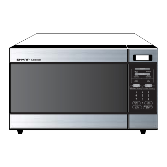
R-290H(S) APPEARANCE VIEW OVEN 10 4 1. Door open button 6. Door seals sealing surfaces 11. Power supply cord 2. Oven lamp 7. Coupling 12. Ventilation openings 3. Door hinges 8. Control panel 13. Turntable 4. Door safety latches 9. Liquid crystal display 14. -
Page 6: Operation Sequence
R-290H(S) OPERATION SEQUENCE OFF CONDITION The oven lamp remains on even if the oven door is Closing the door activates all door interlock switches opened after the cooking cycle has been interrupted, (1st. latch switch, 2nd. interlock relay control switch). -
Page 7: Function Of Important Components
R-290H(S) FUNCTION OF IMPORTANT COMPONENTS TEMPERATURE FUSE DOOR OPEN MECHANISM The temperature fuse, located on the top of the oven The door is opened by pushing the open button on the cavity, is designed to prevent damage to the oven by fire. -
Page 8: Servicing
3D checks and re-examine the connections to screwdriver. the component being tested. Sharp recommend that wherever possible fault-finding is carried out with the supply disconnected. It may, in some cases, be necessary to connect the supply after the outer case has been removed, in this event carry out 3D checks and then disconnect the leads to the primary of the power transformer. - Page 9 R-290H(S) CK = Check / RE = Replace TEST PROCEDURE A B C D E E E F G G H K M N I L J RECKCKRE CKCKCKCKCK POSSIBLE CAUSE DEFECTIVE PARTS PROBLEM CONDITION Home fuse blows when power supply cord is plugged into wall outlet.
-
Page 10: Test Procedure
R-290H(S) TEST PROCEDURES PROCEDURE COMPONENT TEST LETTER MAGNETRON TEST NEVER TOUCH ANY PART IN THE CIRCUIT WITH YOUR HAND OR AN INSULATED TOOL WHILE THE OVEN IS IN OPERATION. CARRY OUT 3D CHECKS. Isolate the magnetron from the high voltage circuit by removing all leads connected to the filament terminal. - Page 11 R-290H(S) TEST PROCEDURES PROCEDURE COMPONENT TEST LETTER Room temperature ....... To = 21˚C Initial temperature ....T1 = 11 C Temperature after (52 + 3) = 55 sec..............T2 = 21 C Temperature difference Cold-Warm ..............T1 = 10 C Measured output power The equation is “P = 80 x T”...
- Page 12 R-290H(S) TEST PROCEDURES PROCEDURE COMPONENT TEST LETTER HIGH VOLTAGE CAPACITOR TEST CARRY OUT 3D CHECKS. A. Isolate the high voltage capacitor from the circuit. B. Continuity check must be carried out with measuring instrument which is set to the highest resistance range.
- Page 13 R-290H(S) TEST PROCEDURES PROCEDURE COMPONENT TEST LETTER FUSE T6.3A CARRY OUT 3D CHECKS. If the fuse T6.3A is blown when the door is opened, check the 1st latch switch, 2nd. interlock relay control switch, monitor switch and 2nd. interlock relay RY2.
- Page 14 R-290H(S) TEST PROCEDURES PROCEDURE COMPONENT TEST LETTER c) Only one indicator does not light up. d) The corresponding segments of all digits do not light up; or they continue to light up. e) Wrong figure appears. f) A certain group of indicators do not light up.
- Page 15 R-290H(S) TEST PROCEDURES PROCEDURE COMPONENT TEST LETTER PROCEDURES TO BE TAKEN WHEN THE FOIL PATTERN ON THE PRINTED WIRING BOARD (PWB) IS OPEN To protect the electronic circuits, this model is provided with a fine foil pattern added to the primary on the PWB, this foil pattern acts as a fuse.
-
Page 16: Touch Control Panel
R-290H(S) TOUCH CONTROL PANEL ASSEMBLY OUTLINE OF TOUCH CONTROL PANEL The touch control section consists of the following units as common electrodes using a Liquid Crystal Display. shown in the touch control panel circuit. 3) Power Source Circuit This circuit generates voltage necessary in the control (1) Key Unit unit from the AC line voltage. - Page 17 R-290H(S) DESCRIPTION OF LSI The I/O signal of the LSI are detailed in the following table. Pin No. Signal Description Auto clear terminal. RESET Signal is input to reset the LSI to the initial state when power is supplied. TEST Connected to GND.
- Page 18 R-290H(S) Pin No. Signal Description Signal similar to K02. When either G8 line on key matrix is touched, a corresponding signal will be input into K00. Signal similar to K02. When either G9 line on key matrix is touched, a corresponding signal will be input into K01.
- Page 19 R-290H(S) SERVICING 1. Precautions for Handling Electronic Components For those models, therefore, it is possible to This unit uses CMOS LSI in the integral part of the check and repair the controls of the touch control circuits. When handling these parts, the following pre- panel while keeping it apart from the oven proper;...
-
Page 20: Component Replacement And Adjustment Procedure
WARNING FOR WIRING To prevent an electric shock, take the following and Oven cavity. manners. 3) Sharp edge: 1. Before wiring, Oven cavity, Waveguide flange, other metallic 1) Disconnect the power supply. plate. 2) Open the door and wedge the door open. - Page 21 R-290H(S) 3. Remove the three (3) screws holding the magnetron to CAUTION: WHEN REPLACING THE MAGNETRON, the waveguide. BE SURE THE R.F. GASKET IS IN PLACE 4. Remove the magnetron from waveguide. AND THE MAGNETRON MOUNTING 5. Now, the magnetron is free.
- Page 22 R-290H(S) Installation cable (edge) and the rubber connector directly with 1. Remove remaining adhesive on the control panel frame your fingers. This is to avoid oxidized. surfaces with a soft cloth soaked in alcohol. Control panel frame 2. Tear the backing paper from the new membrane switch.
- Page 23 R-290H(S) • Do not touch the pliers to the coil of the fan motor 3. Hold the center of the bracket which supports the shaft because the coil may be cut or injured. of the fan motor on the flat table.
- Page 24 R-290H(S) 1ST. LATCH SWITCH, 2ND. INTERLOCK RELAY CONTROL SWITCH AND MONITOR SWITCH REMOVAL and monitor switch are in the lower position and the 1. CARRY OUT 3D CHECKS. 2nd. interlock relay control switch is in the upper 2. Disconnect wire leads from the switches.
- Page 25 R-290H(S) 10.Now, door panel with sealer film is free. Note: The door on a microwave oven is designed to act 11.Tear sealer film from door panel. as an electronic seal preventing the leakage of 12.Now, door panel is free. microwave energy from oven cavity during cook cycle.
-
Page 26: Microwave Measurement
R-290H(S) MICROWAVE MEASUREMENT Recommended instruments are: After adjustment of door latch switches, monitor switch and door are completed individually or collectively, the NARDA 8100 following leakage test must be performed with a survey NARDA 8200 instrument and it must be confirmed that the result meets... -
Page 27: Wiring Diagram
R-290H(S) SCHEMATIC NOTE: CONDITION OF OVEN 1. DOOR CLOSED. 2. CLOCK APPEARS ON DISPLAY. NOTE: " " indicates components with potential above 250V. NOISE FILTER N.O. COM. RY-2 2ND. RY-1 INTERLOCK RELAY CONTROL UNIT 2ND. INTERLOCK RELAY CONTROL SWITCH 1ST. LATCH... -
Page 28: Pictorial Diagram
R-290H(S) -
Page 29: Control Panel Circuit
R-290H(S) COM1 COM2 COM3 SEG1 SEG2 SEG3 SEG4 SEG5 SEG6 SEG7 SEG8 SEG9 SEG10 SEG11 SEG12 SEG13 COM1 SEG14 COM0 SEG15 SEG16 SEG17 SEG18 SEG19 /25v 0.01 /25v 0.01 /25v 0.01 20kF /25v /25v 0.01 4.7k /25v 3.3k HZ4B3 /10v... -
Page 30: Printed Wiring Board
R-290H(S) CHIP UNIT CN-B SIDE CODE (J1) Figure S-3. Printed Wiring Board... -
Page 31: Parts List
R-290H(S) PARTS LIST Note: The parts marked " " may cause undue microwave exposure. The parts marked "*" are used in voltage more than 250V. REF. NO. PART NO. DESCRIPTION Q'TY CODE ELECTRIC PARTS 1- 1 QACCAA048WRZZ Power supply cord... - Page 32 R-290H(S) REF. NO. PART NO. DESCRIPTION Q'TY CODE 6- 2 FROLPA101WRKZ Turntable support 6- 3 TCAUHA214WRR0 K caution label 6- 4 FW-VZB889WREZ Main wire harness 6- 5 TINSEA964WRRZ Instruction book 6- 6 FW-VZB888WREZ Switch harness 6- 7 TSPCND300WRRZ Rating label...
- Page 33 R-290H(S) OVEN AND CABINET PARTS 4-13 1-13 4-11 1-12 4-12 4-14 1-10 4-10 1-11 1-14 1-10...
- Page 34 R-290H(S) CONTROL PANEL PARTS Before attaching Control unit to Control panel, foil side of Control unit must be cleaned by ethyl-alcohol. 3-1-4 3-1-3 3-1-1 DOOR PARTS 3-1-2 3-2-1 3-2-2 5-2-1 5-2-2 5-2-3 MISCELLANEOUS Actual wire harness may be different than illustration.
-
Page 35: Packing And Accessories
R-290H(S) PACKING AND ACCESSORIES TOP PAD ASSEMBLY FPADBA511WRKZ DOOR PROTECT SHEET WRAP COVER SPADPA580WRE0 SSAKHA014WRE0 6-5 INSTRUCTION BOOK 6-1 TURNTABLE TRAY MICROWAVE OVEN BOTTOM PAD ASSEMBLY FPADBA512WRKZ 6-2 TURNRTABLE SUPPORT INTO THE OVEN CAVITY PACKING CASE Not replaceable items. FPAK-A446WRKZ... - Page 36 R-290H(S) COPYRIGHT © 2002 BY SHARP CORPORATION ALL RIGHTS RESERVED. No part of this publication may be reproduced, stored in retrieval systems, or transmitted in any form or by any means, electronic, mechanical, photocopying, recording, or otherwise, without prior written permission of the publisher.
Need help?
Do you have a question about the R-290H and is the answer not in the manual?
Questions and answers