
Related Manuals for Heatmaster 100 N


Summary of Contents for Heatmaster 100 N
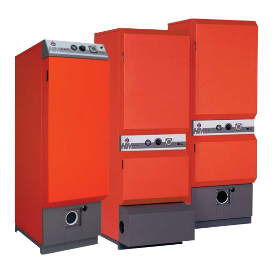
- Page 1 HeatMaster Installation, operating and servicing instructions HeatMaster 60N / 70N / 100N ® HeatMaster 60N / 70N / 100N ® With ACV BG 2000-S premix gas burner HeatMaster 60N / 70N / 100N ® With ACV BM oil burner 664Y0500.A ®...
-
Page 2: Table Of Contents
WARNINGS Who should read these instructions Symbols Recommendations Applicable standards Warnings DESCRIPTION Operating principle Construction features USERS GUIDE Using the boiler Resetting the pressure jet oil or Gas burner Ressetting the BG 2000-S premix gas burner Burner troubleshooting TECHNICAL CHARACTERISTICS Maximum operating conditions Burner chamber plate General features... -
Page 3: Who Should Read These Instructions
WHO SHOULD READ THESE INSTRUCTIONS These instructions should be read by: - the specifying engineer - the installer - the user - the service engineer SYMBOLS The following symbols are used in this manual: Essential instruction for the correct operation of the installation. -
Page 4: Construction Features
Standard equipment The HeatMaster ® 60 N, 70 N and 100 N has the following items as standard : - ON/OFF switch - Summer/Winter switch - Timeclock - Primary circulating shunt pump... - Page 5 A. Thermal reset high limit thermostat B. Manual reset high limit thermostat C. Low water pressure switch D. Primary safety valve Control thermostat ® 60 N Safety features of the HeatMaster EN • 5 ® 70 N and 100 N...
-
Page 6: Using The Boiler
‘Heating System Pressure’ paragraph later in this section. • Low primary water pressure indicator If this indicator lights up, the primary circuit of the HeatMaster requires topping up with water. Please see the ‘Heating System Pressure’ paragraph later in this section. -
Page 7: Resetting The Pressure Jet Oil Or Gas Burner
GAS BURNER • HeatMaster ® 60 N / 70 N and 100 N the lockout indicator is situated on the burner and on the control panel. The red warning light indicates an operating fault.Wait five minutes before resetting the burner.To reset : press the button located on the burner. -
Page 8: Maximum Operating Conditions
1106 1219 L/60’ L/60’ 1835 1835 1573 1573 1101 1067 minutes EN • 8 Ø28 ® ® 70 N HeatMaster 100 N 107,0 96,3 0,65 1”1/2 1” 1” 3,95 ® 70 N HeatMaster ® 100 N 3172 2680 1813 1226... -
Page 9: Electrical Connection
ELECTRICAL CONNECTION WIRING DIAGRAM : HeatMaster 1. 230 V power connection plug 2. ON/OFF switch 3. Temperature high limit cutoff indidicator 4. Manuel reset high limit thermostat 5. Primary circuit low water pressure indicator 6. Low water pressure switch 7. Time clock 8. -
Page 10: Installation
H mm 1098 J mm K mm 1665 Weight empty (kg] HeatMaster ® 60 N Without burner HeatMaster ® 70 N / 100 N Without burner 664Y0500.A INSTALLATION HeatMaster ® HeatMaster ® HeatMaster 60 N 70 N + BG 2000-S/60... -
Page 11: Connection To The Chimney
Outlet pipe This table is based on the equipment offered by ACV and cannot be applied generally. 70 N 100 N 2,11 3,20 The maximum length of concentric flue is 6 meters. A condensation drain outlet must be fitted close to the boiler to prevent condensation products from the chimney running into the boiler. -
Page 12: Domestic Hot Water Connection
DOMESTIC HOT WATER CONNECTION Before pressurizing the central heating circuit (primary) you should first pressurize the domestic hot water tank (secondary). The HeatMaster ® boiler can be connected directly on the domestic hot water circuit. Flush out the system before connecting the domestic hot water part. -
Page 13: Oil Supply Connections - Acv Bm Burners
L (m) H (m) Ø int. 8 mm CONNECTION TO THE GAS - The HeatMaster ® is fitted with a Ø 3/4” (BG 2000-S/60, BG 2000-S/70) and Ø 1” (BG 2000-S/100) female fitting connector, on which you can connect the gas tap. -
Page 14: Filling The Domestic Hot Water And Heating Circuits
After 5 minutes of operation, vent the primary circuit again maintaining the water pressure at 1 bar. Then restart the unit and check the combustion. HeatMaster EN • 14 ® 70 N and 100 N... -
Page 15: Acv Bg 2000-S Premix Gas Burners
• The BG 2000-S burner fitted to the HeatMaster and 100 is controlled by a Honeywell module which controls burner operation and safety. - Page 16 Great Britain Greece Ireland Italy Luxembourg Lithuania Netherlands Poland Portugal Slovenia Slovakia Sweden (*) HeatMaster ® 100 N + BG 2000-S/100 664Y0500.A BURNER FEATURES HeatMaster ® 60 N + BG 2000-S / 60 69,9 62,9 91,2 mbar °C g/sec. 32,1...
- Page 17 2. Burner tube 3. Ionisation probe 4. Burner chamber plate insulation 5. Gas valve 6. Venturi Chamber plate 8. Relay 9. Gas inlet 10. Fan power plug 11. Fan 12. Potentiometer setting 13. Burner plug connector Blue Black Brown Grey...
-
Page 18: Acv Bm 102 And Bm 152 Oil Burners
29,6 EN • 18 G Ø L Ø LK Ø 100 / 82 100 / 123 HeatMaster ® 70 N HeatMaster ® 100 N BM 102 BM 152 69,9 107,0 1,50 2,00 60° 60° 10,5 13,5 12,5 12,5 29,6... -
Page 19: Servicing The Safety Devices
SERVICE INTERVALS ACV recommends that boilers should be serviced at least once a year. The burner must be serviced and tested by a competent engineer. If a boiler is subject to heavy use, it may require servicing more than once a year - consult ACV for advice. SERVICE THE BOILER 1. - Page 20 EN • 20 664Y0500.A...
- Page 21 537D6224 Ø 150 mm 537D6225 Ø 150 mm 537D6210 Ø 150 mm 537D6213 Ø 100 mm 537D6217 Ø 100 mm - L 500 mm 537D6222 Ø 100 mm - 90° 537D6222 Ø 100 mm - 45° 664Y0500.A 537D6212 Ø 150 mm Ø...
- Page 22 HeatMaster ® 30 N / 60 N 21475400 21472400 21478400 21474400 21477400 21471400 21473400 21423026 21476342 664Y0500.A...
- Page 23 507F3033 63438001 49410039 55445007 55426017 557A4002 51305000 51401045 664Y0500.A HeatMaster ® 30 N / 60 N 557A0016 507F2009 507F2010 557A1056 55301200 55426001...
- Page 24 HeatMaster ® 70 N 21475369 21472369 21474369 21473369 21471369 21477369 21478369 2147P152 21476370 664Y0500.A...
- Page 25 507F3033 63438001 497B0001 557A7006 557A1056 55426017 51305000 51401045 664Y0500.A HeatMaster ® 70 N 557A0016 507F2009 507F2010 39438046 55445007 557A4009 55426001...
- Page 26 HeatMaster ® 100 N 21475369 21472370 21474370 21473370 21471370 21477369 21478369 2147P152 21476370 664Y0500.A...
- Page 27 507F3033 63438001 49410071 557A7006 557A1056 55426017 51305000 51401045 664Y0500.A HeatMaster ® 100 N 557A0016 507F2009 507F2010 39438047 55445007 557A4009 55426001...
- Page 28 54766001 54442045 54766001 54442045 664Y0500.A HeatMaster ® 30 N / 60 N 54441008 54764021 54452000 HeatMaster ® 70 N / 100 N 54441008 54764021 54452000 54322000 54764009 54766016 54766017 54322000 54764006 54766016 54766017...
Need help?
Do you have a question about the 100 N and is the answer not in the manual?
Questions and answers