
Subscribe to Our Youtube Channel
Related Manuals for Heatmaster HM 101


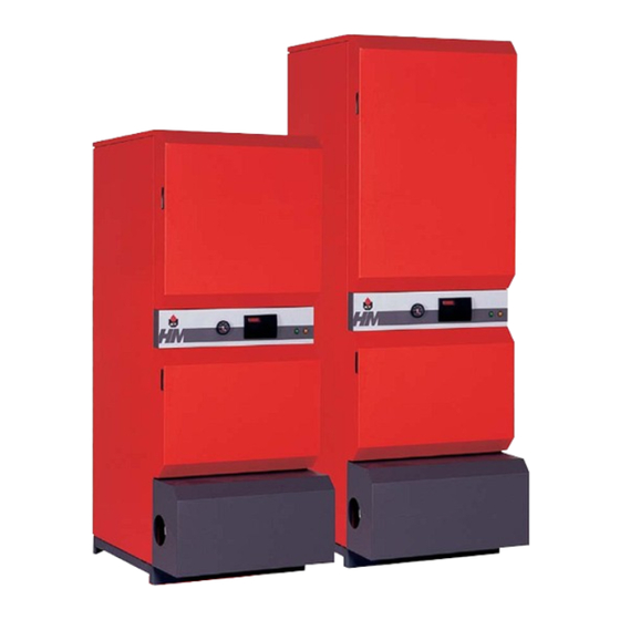
Summary of Contents for Heatmaster HM 101
- Page 1 HeatMaster Installation, Operating and Servicing Instructions HM 71 HM 101 excellence in hot water 66401100...
-
Page 2: Table Of Contents
INDEX INTRODUCTION Intended users of these instructions Symbols Applicable standards Warnings DESCRIPTION Operating principle Construction features TECHNICAL SPECIFICATION Dimensions General features Maximum operating conditions Domestic hot water performances HeatMaster control settings INSTALLATION Boiler room Chimney connections Hot water connections Heating connection Electrical connection Wiring diagram COMMISSIONING... -
Page 3: Construction Features
DESCRIPTION OPERATING PRINCIPLE The HeatMaster is a high performance, direct fired hot water storage heater, which has indirect heat transfer due to its Tank-in-Tank construction. At the heart of the HeatMaster is a stainless steel cylinder through which the flue tubes pass. This is surrounded by a mild steel shell containing the primary water (neutral fluid). - Page 4 DESCRIPTION Top cover Flue reduction collar Automatic air vent Central heating flow pipe Domestic cold water inlet Domestic hot water outlet Heating circuit filling valve with removable hose Flue pipes and turbulators and non-return valve Primary expansion vessel Tank-in-Tank heat exchanger Insulation Primary shunt pump Burner...
-
Page 5: Technical Specification
The units are delivered fully assembled, tested and packed on a timber base with shockproof edges and protected by heat-shrunk plastic film. On delivery and after unpacking, check the equipment for damage. For transport purposes, refer to the weights and dimensions given below. A mm HM 71 1743 HM 101 2093 GENERAL FEATURES Fuel Maximum Input Maximum Output Maintenance loss at 60 °C of rated value... -
Page 6: Domestic Hot Water Performances
The regulator compares the primary temperature with the setting and modulates. The room thermostat detects the heating demand HM 71 HM 101 2. Hot water mode The detector located in the secondary tank detects the hot water demand. When a draw-off is detected the controller goes to “hot water demand”... -
Page 7: Chimney Connections
INSTALLATION BOILER ROOM Important • Keep vents free at all times. • Do not store inflammable products in the boiler room. • Do not store corrosive products near the boiler, such as paints, solvents, chlorine, salt, soap and other cleaning products. •... - Page 8 Balanced flue boiler connection type: C • C13: concentric horizontal connection • C33: concentric vetical connection • C53: parallel chimney connection • C63: concentric vertical connection without terminal (only in Germany and Luxembourg). Maximum length concentric : 6 metres Maximum length parallel : 12 metres Note: a 90 degree bend = 1 metre equivalent length A condensation drain outlet must be fitted close to the boiler to prevent condensation products from the chimney running into the boiler.
-
Page 9: Hot Water Connections
INSTALLATION HOT WATER CONNECTIONS Pressure reducing valve If the mains water pressure is greater than 6 bar, a pressure reducing valve must be fitted. Expansion relief valve The tank expansion relief valve must be ACV approved and calibrated to a maximum of 7 bar. The valve discharge must be connected to the drain. -
Page 10: Heating Connection
HEATING CONNECTION The HeatMaster has two connections at the rear that can be used to connect a central heating circuit. Connecting a heating system may reduce the domestic hot water performance. WARNING The maximum pump motor load for the MCBA is 250 Watt. -
Page 11: Electrical Connection
This contact closes if the MCBA is in lock out. 2 - External gas valve / burner - run indication: This contact closes if a heat request is present and the fan is running. 3 - Domestic Hot Water pump: This contact closes if a Domestic Hot water heat request is present. -
Page 12: Wiring Diagram
Hot water temperature detector NTC 3 Summer/winter switch Fan power supply 230 volts Fan PWM Gas valve rectifier Gas valve rectifier (HM 101) Gas pressure switch (optional) 1 2 3 4 5 6 Y/Gr N T1 T2 S3 B4 N T1 T2 S3 B4... -
Page 13: Filling The Hot Water And Heating Circuits
As it passes through, the air produces a pressure differential in the constriction of the venturi and sucks the gas into the venturi outlet. A perfect mix of air and gas then passes through the fan to the burner tube. - Page 14 Burner tube Ignition electrode Air collector Gas valve Gas inlet BURNER FEATURES HM 101 25.0 - 107 / 22.0 - 110 (*) 23.0 - 96.3 / 20.2 - 99.0 (*) 92.1 2.64 - 11.32 3.80 - 13.17 0.94 - 4.50 11.5 - 49.2...
-
Page 15: Servicing The Safety Devices
MAINTENANCE SERVICE INTERVALS ACV recommends that boilers should be serviced at least once a year. The burner must be serviced and tested by a competent engineer. If a boiler is subject to heavy use, it may require servicing more than once a year - consult ACV for advice. -
Page 16: Using The Boiler
USING THE BOILER Your system should be serviced at least once a year by a qualified engineer. If the boiler is subject to heavy use, it may require servicing more than once a year - consult your service engineer for advice. Starting the burner: In normal operation, the burner starts automatically whenever the boiler temperature falls below the set... -
Page 17: Control Settings
• “b25”: dT1/dt > Maximum Gradient T1 • “b26”: Minimum gas pressure switch not closed • “b28”: no fan signal • “b29”: fan signal, incorrect fan rotation • “b30”: T1 - T2 > Max. delta • “b33”: NTC3 short circuit •... - Page 18 - if the fan is turning: • check the PWM connection • if the problem persists after 2 resets, change the fan • if the problem persists after 2 resets, change the MCBA - if the fan is not turning: •...
-
Page 19: Service Record
SERVICE RECORD INSTALLATION DETAILS Date installed: Flue gas T° : % CO Efficiency : (min. load) % CO Gas pressure : (max. load) Name and signature : SERVICE RECORD Date serviced : Flue gas T° : % CO Efficiency : (min. - Page 20 excellence in hot water INTERNATIONAL ACV international n.v KERKPLEIN, 39 B-1601 RUISBROEK - BELGIUM TEL.: +32 2 334 82 20 FAX: +32 2 378 16 49 E-MAIL: international.info@acv-world.com BELGIUM ACV BELGIUM nv/sa KERKPLEIN, 39 B-1601 RUISBROEK-BELGIUM TEL.: +32 2 334 82 40 FAX: +32 2 334 82 59 E-MAIL: belgium.info@acv-world.com CHILE...
Need help?
Do you have a question about the HM 101 and is the answer not in the manual?
Questions and answers