Table of Contents
Advertisement
Quick Links
Advertisement
Table of Contents

Related Manuals for Radyne DM240XR


Summary of Contents for Radyne DM240XR
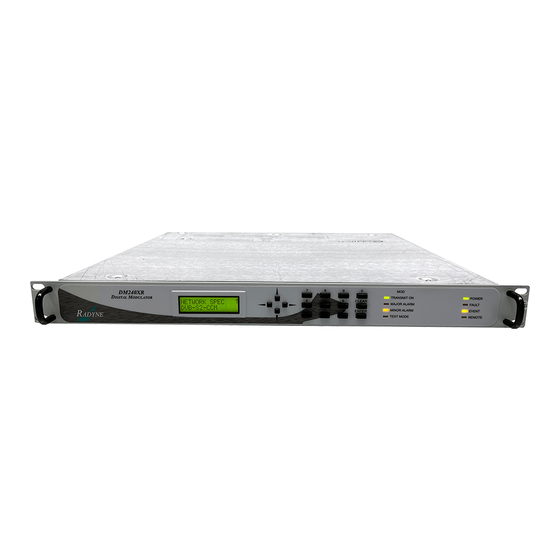
- Page 1 DM240XR High-Speed Digital Modulator Installation and Operation Manual IMPORTANT NOTE: The information contained in this document supersedes all previously published information regarding this product. This manual is subject to change without prior notice. MN-DM240XR Revision 13...
- Page 3 DM240XR High-Speed Digital Modulator Installation and Operation Manual Part Number MN-DM240XR Revision 13 Copyright © 2012 Comtech EF Data. All rights reserved. Printed in the USA. Comtech EF Data, 2114 West 7th Street, Tempe, Arizona 85281 USA, 480.333.2200, FAX: 480.333.2161...
- Page 4 Blank Page...
-
Page 5: Table Of Contents
Table of Contents CHAPTER 1. INTRODUCTION .................. 1–1 Description ..........................1–1 CHAPTER 2. INSTALLATION ................... 2–1 Installation Requirements...................... 2–1 Unpacking ..........................2–2 Removal and Assembly ......................2–2 Mounting Considerations ...................... 2–2 Modulator Checkout ......................2–3 2.5.1 Initial Power-Up ....................... 2–3 CHAPTER 3. - Page 6 4.4.6 Software Compatibility....................4–37 4.4.7 RLLP Summary ......................4–38 4.4.8 DM240XR Opcode Command Set .................. 4–38 Ethernet Port User Interface ....................4–39 Simple Network Management Protocol (SNMP) ..............4–39 The Management Information Base (MIB) ................. 4–39 4.7.1 Directory {internet 1} 1.3.6.1.1 ..................4–39 4.7.2...
- Page 7 DVB-S Series Configuration ....................7–5 7.9.1 DVB-S2 Series Configuration ..................7–5 7.10 Data Rates (DVB-S) ....................... 7–5 7.10.1 Data Rates (DVB-S2) ....................... 7–7 CHAPTER 8. SNMP ....................8–1 CHAPTER 9. REMOTE OPERATIONS ..............9–1 DM240XR Opcode Command Set ..................9–1...
- Page 8 Table of Contents Revision 13 DM240XR High-Speed Digital Modulator MN-DM240XR Modulator Command Set ...................... 9–1 Detailed Command Descriptions ................... 9–3 CHAPTER 10. WEB BROWSER ................10–1 10.1 Web Browser User Interface ....................10–1 10.2 Configuring Your PC ......................10–2 10.2.1 LED Indicators .......................
- Page 9 Table of Contents Revision 13 DM240XR High-Speed Digital Modulator MN-DM240XR APPENDIX C. WEB BROWSER QUICK SETUP GUIDE ........... C–1 Introduction .......................... C–1 Web Users Configuration ..................... C–1 C.2.1 Change Web User Name ....................C–3 C.2.2 Change Authentication Password..................C–3 C.2.3 Change Access Rights ......................C–4 Modem Web Site ........................
- Page 10 Table of Contents Revision 13 DM240XR High-Speed Digital Modulator MN-DM240XR Blank Page viii...
-
Page 11: About This Manual
PREFACE About this Manual This manual describes the installation and operation for the Radyne DM240XR. This is an informational document intended for the persons responsible for the operation and maintenance of the DM204XR. Conventions and References Patents and Trademarks See all of Comtech EF Data's Patents and Patents Pending at http://patents.comtechefdata.com. - Page 12 DM240XR Revision 13 Preface MN-DM240XR Safety Compliance EN 60950 Applicable testing is routinely performed as a condition of manufacturing on all units to ensure compliance with safety requirements of EN60950.This equipment meets the Safety of Information Technology Equipment specification as defined in EN60950.
- Page 13 DM240XR Revision 13 Preface MN-DM240XR Warranty Policy Comtech EF Data products are warranted against defects in material and workmanship for a specific period from the date of shipment, and this period varies by product. In most cases, the warranty period is two years. During the warranty period, Comtech EF Data will, at its option, repair or replace products that prove to be defective.
- Page 14 DM240XR Revision 13 Preface MN-DM240XR Customer Support Support Business Hours – Monday Through Friday – 8:00 a.m. to 5:00 p.m. (MST): Comtech EF Data & Radyne Advanced VSAT Solutions Tel:+1.480.333.4357 Satellite Modems Fax:+1.480.333.2500 Modem Accessories Email: techsupport@comtechefdata.com Amplifiers Converters Transceivers...
-
Page 15: Chapter 1. Introduction
Chapter 1. INTRODUCTION This chapter provides an overview of the DM240XR High-Speed Digital Modulator. The DM240XR will be referred to in this manual as “the DM240XR”, “the modulator”, or “the unit”. Description The New Standard in Digital Modulator Performance Radyne’s DM240XR family of High-Speed Modulators is the ideal choice to meet the exacting standards of High Data-Rate Video, Internet and Fiber Restoral Satellite Applications. - Page 16 Menus are specifically designed for ease of use and quick online operation as well as changes in all modulator configurations. The DM240XR supports optional 1:1 Redundancy for data, IF or both offering superior system reliability based on customer needs and applications.
-
Page 17: Chapter 2. Installation
1 RU mounting space (1.75 inches) vertically and 17 inches of depth. Including cabling, a minimum of 20-inches of rack depth is required. The rear panel of the DM240XR is designed to have power enter from the left and IF cabling enter from the right when viewed from the rear of the unit. -
Page 18: Unpacking
The DM240XR is designed for indoor applications only. The only tools required for rack mounting the DM240XR is a set of four rack mounting screws and an appropriate screwdriver. Rack mount brackets are an integral part of the cast front bezel of the unit and are not removable. -
Page 19: Modulator Checkout
If a failure is detected, the Fault LED is illuminated. The initial field checkout of the DM240XR can be accomplished from the front panel, Terminal Port, Remote Port, or Ethernet Port. MN-DM240XR– Revision 13... - Page 20 DM240XR High-Speed Digital Modulator Installation Notes: MN-DM240XR– Revision 13 2–4...
-
Page 21: Chapter 3. Theory Of Operation
RF Carrier produced from the Transmit IF Synthesizer Circuitry. Since the baseband processing is completely digital, many different variations of signal processing can be performed. Therefore, the DM240XR is one of the most flexible digital modulators available today. DVB-S Operation The DVB-S version of the DM240XR complies with both EN300-421 and EN301-210 ETSI Specifications. -
Page 22: Dvb-S2-Bs-Nbc Operation
Figure 3-1. Functional Block Diagram DVB-S2-BS-NBC Operation The DVB-S2-BS-NBC version of the DM240XR complies with the ETSI EN 302 307 V1.1.1 (2004-01) specification for non-backward compatible broadcast services. A block diagram of the signal flow is shown in Figure 3-2 below. -
Page 23: Chapter 4. User Interfaces
Terminal Front Panel User Interface The front panel of the DM240XR allows for complete control and monitor of all DM240XR parameters and functions via a keypad, LCD display and status LEDs. The front panel layout is shown in Figure 4−1, showing the location and labeling of the front panel. -
Page 24: Front Panel Lcd Display
Yellow Indicates the modulator is involved in a current test mode activity. Power Green Indicates the DM240XR unit is currently powered up. Fault Indicates a common fault exists such as power out of spec. Event Yellow Indicates that events have been logged into the event buffer. -
Page 25: Parameter Setup
Depress <ENTER> again and re-enter the new parameters followed by <ENTER>. Following a valid input, the DM240XR will place the new setting into the nonvolatile SRAM making it available immediately and available the next time the unit is powered-up. - Page 26 DM240XR High-Speed Digital Modulator User Interfaces FFigure 4-2. DM240XR Main Programming Menu MN-DM240XR– Revision 13 4–4...
-
Page 27: Front Panel Control Screen Menus
Figure 4-3. Entering New Parameters Front Panel Control Screen Menus IMPORTANT The complete set of DM240XR Front Panel Control Screens is made up of Main Menus. Each Main Menus has several Option and Parameter Screens. 4.3.1 Main Menus The Main Menus available from the Front Panel of the DM240XR are:... -
Page 28: Modulator Menu Options And Parameters
RF switch that the DM240XR is attached (prime or backup). The second status line indicates if the output of the DM240XR is the active output of the RF switch (online) or inactive (offline). Prime Mode: Indicates the unit is configure as the primary... - Page 29 DM240XR High-Speed Digital Modulator User Interfaces configure this menu when user desires to display the satellite uplink RF frequency on the RF Menu. LO FREQ ( MHz): {4000 MHz to 50000 MHz or 0 to bypass} Enter the LO frequency of the BUC to correctly display the RF satellite output frequency in the RF Menu.
- Page 30 Allows the DM240XR Modulator to implement the AutoEQ™ coefficient values as specified by the EQ Select. EQ SELECT: None, User Specified Name} Allows the DM240XR Modulator to select the stored AutoEQ™ coefficient file to be implemented. Up to 32 User Nameable storage locations are available. RXIF: {950 –...
-
Page 31: Interface Menu Options And Parameters
MSE can be monitored reflecting the Reference Acquisition process. Upon successful completion of the Reference Acquisition, the REF ACQ will revert to the “Normal” state, and the event log of the DM240XR will reflect “REF ACQ SUCCESSFUL”. RESTORE EQ CAL: {Filename} Allows the selected Calibration coefficient file to be Restored. -
Page 32: Plug-In Interface Card (Piic)
DM240XR High-Speed Digital Modulator User Interfaces 4.3.3.1 Plug-In Interface Card (PIIC) ACTIVE INPUT: {SLOT 1, SLOT 2, SLOT 3} This menu is displayed when the interface is configured in Manual Mode. Active Input selection allows the user to select the terrestrial slot that will be active. - Page 33 DM240XR High-Speed Digital Modulator User Interfaces INTERFACE TYPE: {ASI/Advanced ASI, HSSI, M2P Parallel, DVB Parallel (RS422 or LVDS), RS530/RS422 Serial, Ethernet 100/1000 Base-T, Direct TV PECL} Enter the Terrestrial Interface type. IMPORTANT Only the Interface types that are installed may be selected. The Ethernet Interface will add additional menus that are identified in section 4.2.3.2...
-
Page 34: Ethernet Interface (J1)
The Transmit Clock (SCT) supplied by the DM240XR is always Output. Normally, this clock is used to clock the data out of the data source and then return it to the SCTE input. The DM240XR is then set to SCTE mode eliminating any possible clock skew. - Page 35 DM240XR High-Speed Digital Modulator User Interfaces INTERFACE MENU - The following new items are available under the Interface menu INTERFACE TYPE: {ETHERNET} When the slot with GigEth card is active, the interface type will be Ethernet. TERR FRAMING: {PROMPEG COP3, BRIDGE} Pro MPEG COP 3 –...
- Page 36 DM240XR High-Speed Digital Modulator User Interfaces JITTER TRACKING: {Widest, Wide, Mid Level, Narrow, Narrowest} Allows the operator to select how the modulator reacts to and compensates for jitter. Because the modulators transmit clock is locked to the incoming data stream, care must be taken when selecting this parameter.
- Page 37 DM240XR High-Speed Digital Modulator User Interfaces Prime Column FEC packets must arrive on Prime UDP port + 2 Prime Row FEC packets must arrive on Prime UDP port SOURCE IP ADDR: {XXX.XXX.XXX.XXX} IMPORTANT This menu is displayed in when the Prime IP Address is configured for Multicast mode: The user can specify a source IP address for the prime to listen to.
- Page 38 DM240XR High-Speed Digital Modulator User Interfaces Backup Row FEC packets must arrive on Prime UDP port + 4 SOURCE IP ADDR: {XXX.XXX.XXX.XXX} IMPORTANT This menu is displayed in Multicast mode only: The user can specify a source IP address for the backup to listen to. When a non-zero IP address is entered, the backup will only accept multicast packets addressed to it on its backup port from the specified source.
- Page 39 DM240XR High-Speed Digital Modulator User Interfaces 100 Mbps Full: The unit has established a valid 100 Mbps Full Duplex link 1 GIG Half: The unit has established a valid Gigabit Half Duplex link 1 GIG Full: The unit has established a valid Gigabit Full Duplex...
- Page 40 DM240XR High-Speed Digital Modulator User Interfaces These menus are displayed when in COP3 Mode only. BACKUP DATA {No Activity, Online Activity, Offline Activity} No Activity: The backup port is not receiving any data packets Online Activity: The backup port is currently the online port...
- Page 41 DM240XR High-Speed Digital Modulator User Interfaces Indicates the number of times the modulator has had to use the FEC data stream to generate a missing or erred data packet. REORDERED PACKETS: {count value} Indicates the number of packets that have been received out of order.
-
Page 42: Rf Switch Menu Options And Parameters
ACTIVATE BACKUP Pressing ENTER causes the backup side of the RF switch to be selected as online. (BACKUP|PRIME) STATUS: {NORMAL, FAULT} This is the status of the other DM240XR connected to the RF switch. FAULT TEST: {NORMAL, FAULT} Asserts the fault signal to the RF switch for testing purposes. - Page 43 DM240XR High-Speed Digital Modulator User Interfaces SYSREF PLL: {PASS/FAIL, UNMASKED/MASKED} COMPOSITE PLL: {PASS/FAIL, UNMASKED/MASKED} SYMBOL PLL: {PASS/FAIL, UNMASKED/MASKED} TERR INTERFACE: {PASS/FAIL, UNMASKED/MASKED} STREAM: {PASS/FAIL} TX MINOR (Menu) TERR CLK ACT: {PASS/FAIL, UNMASKED/MASKED} TERR DATA ACT: {PASS/FAIL, UNMASKED/MASKED} FRAME SYNC: {PASS/FAIL, UNMASKED/MASKED}...
-
Page 44: System Menu Options And Parameters
DM240XR High-Speed Digital Modulator User Interfaces TX MINOR (Menu) TERR CLK ACT: {PASS/FAIL} TERR DATA ACT: {PASS/FAIL} FRAME SYNC: {PASS/FAIL} FIFO: {PASS/FAIL} OUTPUT LEVEL: {PASS/FAIL} COMMON (Menu) +12 VOLTS: {PASS/FAIL} -12 VOLTS: {PASS/FAIL} + 5 VOLTS: {PASS/FAIL} CLEAR LATCHED: {((ENTER))} Pressing ENTER will clear the latched alarms. - Page 45 DM240XR High-Speed Digital Modulator User Interfaces BAUD RATE: {150, 300, 600, 1200, 2400, 4800, 9600, 19200, 38400, 115200} Allows the user to select the Computer Baud Rate. TCP/IP (menu) BOOTp SERVER TAG: {128 – 257, default is 206} Only used if Bootp is selected in Boot Mode. Should be consistent with the tag expected by the users Bootp Server.
- Page 46 DM240XR High-Speed Digital Modulator User Interfaces ROUTER IP ADDR {XX.XX.XX.XX} Hexidecimal Address {ddd.ddd.ddd.ddd} Decimal Address The IP Address of the Local Network Router. If a router is present on the local network, this address must be consistent with the IP Mask and the subnet of the modem. If no router is present, then the address should be set to a foreign address.
- Page 47 DM240XR High-Speed Digital Modulator User Interfaces When V3 is used, three contexts are supported: public, mib2, and dev. Context, Authentication and Privacy are a portion of each SNMPV3 message. The public context will only allow the user to see the sysoid of the unit.
- Page 48 DM240XR High-Speed Digital Modulator User Interfaces numeric characters. Alpha characters can be entered using the up and down arrow keys. Numeric characters can be selected by using the number keys on the front panel. The user can clear all characters from the front panel screen.
- Page 49 DM240XR High-Speed Digital Modulator User Interfaces Admin: At this highest access right, the users can monitor and control the modems parameters, change any user’s name and authentication password, and modify IP network settings. Admin setting allows access to the entire site.
- Page 50 DM240XR High-Speed Digital Modulator User Interfaces FTP (menu) PORT: {XXXX} FTP Port number must be set the same value on DM240XR and FTP program USER ID: {xxxxxxxx} User to select USER ID. The user can modify the user ID. The user ID can have up to 14 characters supporting alpha and numeric characters.
- Page 51 RECEIVE TIMEOUT: {X.X MINUTES} This value is factory set, and should only be adjusted as directed by your Network administrator or Radyne Customer Service. REPLY TIMEOUT: {XX secs} This value is factory set, and should only be adjusted as directed by your Network administrator or Radyne Customer Service.
-
Page 52: Test Menu Options And Parameters
For more information see Appendix D, AutoEQ™ Remote Port User Interface The Remote Port of the DM240XR allows for complete control and monitor functions via an RS- 485 Serial Interface. Control and status messages are conveyed between the DM240XR and the subsidiary modems, and the host computer using packetized message blocks in accordance with a proprietary communications specification. -
Page 53: Protocol Structure
If S2 is followed by a space, it is considered a start bit for the data byte and not part of the actual data (B The COMMSPEC developed for use with the Radyne Link Level Protocol (RLLP) organizes the actual monitor and control data within a shell, or "protocol wrapper” that surrounds the data. The format and structure of the COMMSPEC message exchanges are described herein. - Page 54 DM240XR High-Speed Digital Modulator User Interfaces IMPORTANT All nodes on a given control bus have a unique address that must be defined. <DESTINATION ID> - The Destination Identifier specifies the multidrop address of the device(s) to which the message is sent.
- Page 55 DM240XR High-Speed Digital Modulator User Interfaces Table 4-4. Checksum Calculation Example BYTE FIELD DATA CONTENT RUNNING CHECKSUM <BYTE COUNT> (Byte 1) 00h = 00000000b 00000000b <BYTE COUNT> (Byte 2) 02h = 00000010b 00000010b <SOURCEID> F0h = 11110000b 11110010b <DESTINATION ID>...
-
Page 56: Frame Description And Bus Handshaking
This "GOOD MESSAGE" Opcode is one of nine global responses. Global response Opcodes are common responses, issued to the M&C computer or to another device that can originate from and are interpreted by all Radyne equipment in the same manner. These are summarized as follows: MN-DM240XR–... - Page 57 DM240XR High-Speed Digital Modulator User Interfaces RESPONSE OPCODE DESCRIPTION OPCODE Good Message 0000h Bad Parameter 00FFh Bad Opcode 00FEh IF Frequency Error 0401h Data Rate Error 0404h External Reference Error 0406h Frequency Reference Source Error 0407h Modulation Type Error 0408h...
-
Page 58: Collision Avoidance
DM240XR High-Speed Digital Modulator User Interfaces 4.4.5 Collision Avoidance When properly implemented, the physical and logical devices and ID addressing scheme of the COMMSPEC normally precludes message packet contention on the control bus. The importance of designating unique IDs for each device during station configuration cannot be overemphasized. -
Page 59: Software Compatibility
Volatile Section. If the remote M&C is not aware of the newly added features to the Radyne product, it should disregard the parameters at the end of the Non-Volatile Section and index to the start of the Volatile Section. -
Page 60: Rllp Summary
DM240XR High-Speed Digital Modulator User Interfaces If packets are handled in this fashion, there will also be backward-compatibility between Radyne equipment and M&C systems. Remote M&C systems need not be modified every time a feature is added unless the user needs access to that feature. -
Page 61: Ethernet Port User Interface
DM240XR High-Speed Digital Modulator User Interfaces Ethernet Port User Interface The Ethernet Port of the DM240XR allows for complete control and monitoring of all DM240XR parameters and functions via a 10 Base-T or 100 Base-T Ethernet Connection. Simple Network Management Protocol (SNMP) -
Page 62: Private {Internet 4} 1.3.6.1.4
SMI. Radyne Corporation’s Private Enterprise Number is 2591. Other products are added to Radyne Corporation’s subtree as they become remotely manageable through SNMP. -
Page 63: Terminal Port User Interface
Figure 4-4b. Object Identifiers in the Management Information Base (Figure 2 of 2) Terminal Port User Interface The Terminal Port of the DM240XR supports an asynchronous control protocol. It is configured to support RS-232 signal levels. This port is intended for use in computer-based remote M&C. -
Page 64: Connecting The Terminal
DM240XR High-Speed Digital Modulator User Interfaces 4.8.1 Connecting the Terminal Connect the Terminal to the Terminal Connector (J1) on the rear of the unit using the RS- 232 null modem Cable. Verify that your emulation software is set to the following: ... - Page 65 DM240XR High-Speed Digital Modulator User Interfaces Figure 4-6. Modulator Menu Figure 4-7. Event Log Menu MN-DM240XR– Revision 13 4–43...
- Page 66 DM240XR High-Speed Digital Modulator User Interfaces Figure 4-8. Multi-PIIC Control Menu Figure 4-9. Test Control Menu MN-DM240XR– Revision 13 4–44...
- Page 67 DM240XR High-Speed Digital Modulator User Interfaces Figure 4-10. TCP/IP/SNMP Control Menu Figure 4-11. Front Panel/RLLP/Terminal Control Menu MN-DM240XR– Revision 13 4–45...
- Page 68 DM240XR High-Speed Digital Modulator User Interfaces Figure 4-12. RF Redundancy Switch Menu Figure 4-13. Gig Ethernet Terrestrial Menu Note: Only displayed when the Ethernet Data Interface is installed. MN-DM240XR– Revision 13 4–46...
- Page 69 DM240XR High-Speed Digital Modulator User Interfaces Figure 4-14. SYSTEMS CONTROL Menu MN-DM240XR– Revision 13 4–47...
- Page 70 DM240XR High-Speed Digital Modulator User Interfaces Notes: MN-DM240XR– Revision 13 4–48...
-
Page 71: Chapter 5. Rear Panel Interfaces
DM240XR Connections All DM240XR connections are made to labeled connectors located on the rear of the unit. Any connection interfacing to the DM240XR must be the appropriate mating connector. DM240XR Optional Data Interfaces are shown in Figures 5-1b –... - Page 72 Figure 5-1d. DM240XR Rear Panel Connectors (ASI OUT) Figure 5-1e. DM240XR Rear Panel Connectors (Serial PECL) Figure 5-1f. DM240XR Rear Panel Connectors (DVB/M2P RS422 PARA) Figure 5-1g. DM240XR Rear Panel Connectors (DVB/LVDS PARA) Figure 5-1h. DM240XR Rear Panel Connectors (HSSI) Figure 5-1i.
-
Page 73: Ac Power
DM240XR High-Speed Digital Modulator Rear Panel Interfaces AC Power The unit is powered from a 100 – 240 VAC, 50 – 60 Hz source. Maximum unit power consumption is 25 W. The switch turns power on and off to the unit. A chassis ground connection can be made at the stud located to the lower right of the AC Power Connector. -
Page 74: External Reference (Input)
DM240XR High-Speed Digital Modulator Rear Panel Interfaces External Reference (Input) The External Reference Input (J8) is supplied to allow the customer to phase-lock the modulator’s internal oscillator to an external reference. This female BNC Connector accepts a 1.5 – 5 Vp-p @ 50 Ohms. The frequency range of the external reference is 1 –... -
Page 75: Alarm Port
(J11). The output power level is programmable from -25 to 0 dBm in 0.1 dBm steps. 5.9.1 Output Monitor Port (J9) The output monitor port on the DM240XR is an 50 Ohm SMA female connector. The monitor is a sample of the output frequency that is –20dBc +/-5dB from the output frequency power level. -
Page 76: Rf Redundancy Switch Control (J2)
DM240XR High-Speed Digital Modulator Rear Panel Interfaces 5.10 RF Redundancy Switch Control (J2) The Each modulator has a 9-pin D-sub connector for the switch. A 1:1 cable is connected from each modulator to the switch. The pinout for the control connector is listed in Table 5-5. -
Page 77: Plug-In Interface Cards (Piics)
DM240XR High-Speed Digital Modulator Rear Panel Interfaces 5.12 Plug-In Interface Cards (PIICs) The DM-240XR provides the customer with 2 standard PIIC slots. With PIIC interfaces there is greater flexibility for changing and upgrading the terrestrial interface. Each of the interfaces described below consists of a single card with a metal back plate. -
Page 78: Asi Monitor
DM240XR High-Speed Digital Modulator Rear Panel Interfaces 5.12.2 ASI Monitor Incoming data from the active PIIC slot is output on this interface (Figure 5-1d), allowing the customer to monitor the incoming data stream. The interface complies with DVB ASI Electrical Specifications. -
Page 79: Dvb (Parallel, Rs-422)
DM240XR High-Speed Digital Modulator Rear Panel Interfaces Table 5-5. M2P RS-422 Parallel - 25-Pin Female Pin No. Signal Name Direction Input Input Input Input Not Connected 5.12.3.2 DVB (Parallel, RS-422) The DVB Interface is also supported on the DB-25 Female Connector. It complies with RS-422 Electrical Specifications. -
Page 80: Parallel Lvds Interface
DM240XR High-Speed Digital Modulator Rear Panel Interfaces Table 5-6. DVB RS-422 Parallel, 25-Pin Female Pin No. Signal Name Direction D2 - Input D1 - Input D0 - Input DVALID - Input SYNC - Input 5.12.4 Parallel LVDS Interface This interface is identical to the Parallel RS-422 Interface except that it complies with the LVDS Electrical Specification. -
Page 81: Ethernet 100/1000 Base-T Interface
DM240XR High-Speed Digital Modulator Rear Panel Interfaces Table 5-9. HSSI (High-Speed Serial Interface) 50-Pin Connector Pin No. (+) Pin No. (–) Signal Name Description Direction 20 - 23 45 - 48 Reserved Output 4 Ancillary from DCE Test Mode Output- 5.12.6 Ethernet 100/1000 Base-T Interface... -
Page 82: Interface (Contact Factory For Availability)
DM240XR High-Speed Digital Modulator Rear Panel Interfaces Table 5-10. RS530 (RS-422) Connector Pin No. Signal Name Signal Direction Terminal Timing A (-) TT-A Input Test Mode Output 5.12.8 G.703 Interface (Contact factory for availability) The G.703 Interface supports the following G.703 Rates: E1, T1, E2, T2, E3, T3, and STS-1. The interface complies with G.703 Electrical Specifications. -
Page 83: Chapter 6. Maintenance And Troubleshooting
The DM240XR modulator requires no periodic field maintenance procedures. Should a unit be suspected of a defect in field operations after all interface signals are verified, the correct procedure is to replace the unit with another known working DM240XR. If this does not cure the problem, wiring or power should be suspect. - Page 84 DM240XR High-Speed Digital Modulator Maintenance and Troubleshooting Notes: MN-DM240XR– Revision 13 6–2...
-
Page 85: Chapter 7. Technical Specifications
Chapter 7. Technical Specifications Introduction This section defines the technical performance parameters and specifications for the DM240XR Digital Modulator. IF Specification Tx IF: 50 to 90 MHz, 100 to 180 MHz (70/140 MHz), 950 to 2050 MHz (L-Band) IF Step Size:... -
Page 86: Baseband Specification
DM240XR High-Speed Digital Modulator Technical Specifications Baseband Specification 7.3.1 DVB-S Compliance EN 300-421 and EN 301-210 Modulation Types: BPSK, QPSK, 8PSK, 16QAM Data Rate: 1 to 59.5 Mbps in 1 bps steps (BPSK) 1 to 119 Mbps in 1 bps steps (QPSK) -
Page 87: Dvb-S2-Acm (Normative Features With Single Transports Streams)
DM240XR High-Speed Digital Modulator Technical Specifications 0.25 0.35 Terrestrial Input Clock Accuracy: 400 ppm (max) Test Pattern: Internal 2 -1 and 2 -1 Pseudo-Random Number Generators IMPORTANT Consult Factory on ACM & VCM, Multiple Transport Streams and Generic Transport Streams Input Stream Synchronizer & Null Packet Deletion 7.3.3 DVB-S2-ACM (Normative Features with Single Transports streams) -
Page 88: Interface Types Available (Piic)
DM240XR High-Speed Digital Modulator Technical Specifications Consult Factory on ACM & VCM, Multiple Transport Streams and Generic Transport Streams Input Stream Synchronizer & Null Packet Deletion Interface Types Available (PIIC) ASI: ASI, Serial, BNC (female) ASI Out: ASI Monitor, Serial, BNC (female) -
Page 89: Options
DM240XR High-Speed Digital Modulator Technical Specifications Size: 19” W x 17” D x 1.75" H (48.3 x 43.2 x 4.45 cm) Options 50 Ohm IF Output (on 70/140 MHz IF) 48 VDC Operation DVB-S Series Configuration Series 100: 1 to 10 Msps, QPSK... - Page 90 DM240XR High-Speed Digital Modulator Technical Specifications DVB-S Series 200 Modulation MPEG Unframed Minimum Maximum Minimum Maximum QPSK 1000000 41470588 1000000 45000000 QPSK 1228758 55294118 1333333 60000000 QPSK 1382353 62205882 1500000 67500000 QPSK 1535948 69117647 1666667 75000000 QPSK 1612745 72573529 1750000...
-
Page 91: Data Rates (Dvb-S2)
DM240XR High-Speed Digital Modulator Technical Specifications 7.10.1 Data Rates (DVB-S2) All Data Rates in Bps. DVB-S2 Series 100 Modulation MPEG Minimum Maximum QPSK 1000000 6564481 QPSK 1000000 7894121 QPSK 1000000 9888581 QPSK 1188304 11883041 QPSK 1322253 13222530 QPSK 1487473 14874731... - Page 92 DM240XR High-Speed Digital Modulator Technical Specifications DVB-S2 Series 300 Modulation MPEG Minimum Maximum QPSK 1000000 44498615 QPSK 1188304 53473684 QPSK 1322253 59501385 QPSK 1487473 66936288 QPSK 1587196 71423823 QPSK 1654663 74459834 QPSK 1766451 79490305 QPSK 9/10 1788612 80487535 8PSK 1779991...
- Page 93 DM240XR High-Speed Digital Modulator Technical Specifications 16APSK 2637201 118674033 16APSK 2966728 133502762 16APSK 3165623 142453039 16APSK 3300184 148508287 16APSK 3523143 158541436 16APSK 9/10 3567342 160530387 *Normal Frame size (64800) no pilot insertion DVB-S2 Series 500 Modulation MPEG Minimum Maximum QPSK...
- Page 94 DM240XR High-Speed Digital Modulator Technical Specifications Notes: MN-DM240XR– Revision 13 7–10...
-
Page 95: Chapter 8. Snmp
Radyne user MIB Object Identifiers description. The privite entereprise number 2591 is a unique identifier assigned to Radyne by the Internet Assigned Numbers Authority (IANA). This number is used to uniquely define vendor specific information such as private MIBs. - Page 96 "Selects the Tx power level in tenths of dBm from +5.0 to -20.0 (70/140MHz), from -5.0 to -30.0 (L-Band). from +0.0 to -25.0 (DM240XR 70/140MHz and L-Band). There is an implied decimal point. For example, a value of 39 represents a transmit power level of +3.9 dBm."...
- Page 97 DM240XR High-Speed Digital Modulator SNMP ::= { radSNMPModNVStatus 3 } radDataRate OBJECT-TYPE SYNTAX INTEGER (0..238000000) ACCESS read-write STATUS current DESCRIPTION "Selects the data rate in bps. Note: Changing data rate will affect symbol rate, see comment at the end of mibtext."...
- Page 98 DM240XR High-Speed Digital Modulator SNMP SYNTAX INTEGER { scte(0), sct(1), none(2) ACCESS read-write STATUS current DESCRIPTION "Selects Tx clock source. 0 selects terrestrial clock (SCTE), 1 selects internal clock (SCT). Modulators using ASI or G.703 interface options must use SCTE at all times."...
- Page 99 DM240XR High-Speed Digital Modulator SNMP g703E3(4), g703T3(5), sts1(6), hssi(7), parallelDVB(8), parallelM2P(9), none(10), directv(11), oc3(13), stm1(14), g703E2(15), g703T2Bal(16), g703T2Unbal(17), g703E1Bal(18), g703E1Unbal(19), g703T1AMI(20), g703T1B8ZS(21), gigEthernet(22) ACCESS read-write STATUS current DESCRIPTION "Selects the various interface types. The following choices are not supported: none(10),...
- Page 100 DM240XR High-Speed Digital Modulator SNMP qam16(3), apsk16(9), apsk32(10) ACCESS read-write STATUS current DESCRIPTION "Selects the modulation type. Note: Changing modulation type will affect the symbol rate and data rate. See note at the end of this section." ::= { radSNMPModNVStatus 18}...
- Page 101 DM240XR High-Speed Digital Modulator SNMP STATUS optional DESCRIPTION "unsupported" ::= { radSNMPModNVStatus 24 } radMajorAlarmMask OBJECT-TYPE SYNTAX INTEGER (0..255) ACCESS read-write STATUS current DESCRIPTION "Major Alarm mask: A bit field. 0 = MASKED, 1 = UNMASKED Bit 0 = Stream...
- Page 102 DM240XR High-Speed Digital Modulator SNMP dual(2), offset(3), posfir(4), negfir(5) ACCESS read-write STATUS current DESCRIPTION "normal, allows normal modulated data output cw, causes the modulator to output pure carrier dual, causes a double sideband output offset, causes a single side band output posfir, uses a positive FIR negfir, uses a negative FIR"...
- Page 103 DM240XR High-Speed Digital Modulator SNMP ACCESS read-write STATUS current DESCRIPTION "Selects the source of clock output from the Terrestrial Interface. See the Clock Source Selection Matrix." ::= { radSNMPModNVStatus 34 } radLastRateControl OBJECT-TYPE SYNTAX INTEGER { symbol(0), data(1), auto(2) ACCESS read-write...
- Page 104 DM240XR High-Speed Digital Modulator SNMP If the Multi-PIIC mode is redundancy, radPrimePiicSlot selects the prime input slot." ::= { radSNMPModNVStatus 40 } radBackupPiicSlot OBJECT-TYPE SYNTAX INTEGER ACCESS read-write STATUS current DESCRIPTION "If the Multi-PIIC mode is redundancy, radBackupPiicSlot selects the backup input slot."...
- Page 105 DM240XR High-Speed Digital Modulator SNMP normal(0), bypassed(1) ACCESS read-write STATUS current DESCRIPTION "Enables/disables the inner forward error correction. The modulator is considered in a test mode when the inner FEC is bypassed." ::= { radSNMPModNVStatus 48 } radRfSwitchRedundancyMode OBJECT-TYPE SYNTAX INTEGER {...
- Page 106 DM240XR High-Speed Digital Modulator SNMP STATUS current DESCRIPTION "Selects the directv physical layer header scrambler sequence index." ::= { radSNMPModNVStatus 54 } radGoldCodeSeqIndex OBJECT-TYPE SYNTAX INTEGER (0..262142) ACCESS read-write STATUS current DESCRIPTION "Selects the gold code sequence index." ::= { radSNMPModNVStatus 55 }...
- Page 107 DM240XR High-Speed Digital Modulator SNMP DESCRIPTION "Selects the backup delay in 100ms steps for the Gig Ethernet card." ::= { radSNMPModNVStatus 61 } radTerrEthAddrPrime OBJECT-TYPE SYNTAX IpAddress ACCESS read-write STATUS current DESCRIPTION "Selects the prime IP address for the Gig Ethernet card."...
- Page 108 "Name of the Tx Equalizer Filter. The filter selected can have up to 8 alphanumeric characters such as CARRIER1." ::= { radSNMPModNVStatus 75 } ---------------------------------------------------------------------------- -- Status information out of Radyne specific MIB radMajorAlarmStatus OBJECT-TYPE SYNTAX INTEGER (0..255) ACCESS read-only...
- Page 109 DM240XR High-Speed Digital Modulator SNMP Bit 7 = Invalid Terrestrial Interface " ::= { radSNMPModStatus 1 } radMinorAlarmStatus OBJECT-TYPE SYNTAX INTEGER (0..255) ACCESS read-only STATUS current DESCRIPTION "Minor Alarm status: A bit field. 0 = PASS, 1 = FAIL Bit 0 = Terr Ethernet data activity detect...
- Page 110 DM240XR High-Speed Digital Modulator SNMP STATUS current DESCRIPTION "Common Alarm latched status: A bit field. 0 = PASS, 1 = FAIL Bit 0 = -12V alarm. Bit 1 = +12V alarm. Bit 2 = +5V alarm. " ::= { radSNMPModStatus 6 } radRevisionNumber OBJECT-TYPE SYNTAX INTEGER (0..255)
- Page 111 DM240XR High-Speed Digital Modulator SNMP Bit 13 = OC3 Interface Present Bit 14..15 = Spares unsupported" ::= { radSNMPModStatus 12 } radLastRateStatus OBJECT-TYPE SYNTAX INTEGER { symbol(0), data(1) ACCESS read-only STATUS current DESCRIPTION "Shows the current rate precedence. See Last Rate Control notes."...
- Page 112 DM240XR High-Speed Digital Modulator SNMP -- radPiicSlotClockActivity OBJECT-TYPE SYNTAX INTEGER { inactive( 0), active( 1) ACCESS read-only STATUS current DESCRIPTION "Indicates clock activity of an interface card in a slot." ::= { radPiicSlotStatusEntry 3 } -- radPiicSlotDataActivity OBJECT-TYPE SYNTAX INTEGER {...
- Page 113 DM240XR High-Speed Digital Modulator SNMP radTerrEthActPrime OBJECT-TYPE SYNTAX INTEGER { disabled(0), noActivity(1), onlineActivity(2), offlineActivity(3) ACCESS read-only STATUS current DESCRIPTION "Shows the data activity of the Gig Ethernet card." ::= { radSNMPModStatus 21 } radTerrEthActPrimeCol OBJECT-TYPE SYNTAX INTEGER { disabled(0), noActivity(1),...
- Page 114 DM240XR High-Speed Digital Modulator SNMP DESCRIPTION "Shows the backup data activity of the Gig Ethernet card." ::= { radSNMPModStatus 26 } radTerrEthJitterFill OBJECT-TYPE SYNTAX INTEGER (0..99) ACCESS read-only STATUS current DESCRIPTION "Percent fill of jitter buffer for the Gig Ethernet card."...
-
Page 115: Chapter 9. Remote Operations
Non-Volatile Section of the Remote Communications Specification, and status of the features, if any, are added at the end of the Volatile Section. If a remote M&C queries two pieces of Radyne Corp. equipment with different revision software, they could respond with two different sized packets. - Page 116 DM240XR High-Speed Digital Modulator Remote Operations Command Opcode Query Mod All 2400h Query Mod Latched Alarms 2405h Query Mod Current Alarms 2408h Query Mod Status 240Bh Query Time 240Eh Query Date 240Fh Query Time and Date 2410h Query Firmware Part/Rev...
-
Page 117: Detailed Command Descriptions
DM240XR High-Speed Digital Modulator Remote Operations Terrestrial Interface Type 2621h Terrestrial Framing 2640h Carrier Set Roll Off 2641h Output Clock Source 2642h Symbol Rate 2643h AASI NULL PID (w/IPSat interface card only) 2656h IPSat Burst Demod Count (w/IPSat interface card only) - Page 118 DM240XR High-Speed Digital Modulator Remote Operations <1> Frequency 0 = Internal, 1 = External Reference Source <1> Modulation 0 = QPSK, 1 = BPSK, 2 = 8PSK, 3 = 16QAM Type 9 = 16APSK, 10 = 32APSK <1> Inner FEC Rate...
- Page 119 DM240XR High-Speed Digital Modulator Remote Operations Source <1> Reserved TBD, Default = 0 <11> Reserved <1> Reserved <1> Major Alarm Bit 0 = Spare Mask Bit 1 = Transmit Oversample PLL Lock Bit 2 = FPGA Config Error Bit 3 = IF Synthesizer PLL Lock...
- Page 120 DM240XR High-Speed Digital Modulator Remote Operations <1> BB Scrambler 0 = Normal, 1 = Bypass Bypass <1> Outer FEC 0 = Normal, 1 = Bypass Bypass <1> Test Pattern 0 = None, 1 = 2 – 1, 23 = 2 <1>...
- Page 121 DM240XR High-Speed Digital Modulator Remote Operations <1> Reserved <1> Major Alarm Bit 0 = Spare Bit 1 = Transmit Oversample PLL Lock Bit 2 = FPGA Config Error Bit 3 = IF Synthesizer PLL Lock Bit 4 = External Reference PLL Lock...
- Page 122 DM240XR High-Speed Digital Modulator Remote Operations Bit 3 = Spare Bit 4 = Spare Bit 5 = Spare Bit 6 = Spare Bit 7 = Spare 0 = Pass, 1 = Fail <1> Reserve <1> +5 Voltage Implied Decimal Point. 49 = +4.9 V <1>...
- Page 123 DM240XR High-Speed Digital Modulator Remote Operations Opcode: <2405h> Query a Modulator’s Latched Alarms Query response <1> Latched Major Bit 0 = Spare Alarm Bit 1 = Transmit Oversample PLL Lock Bit 2 = FPGA Config Error Bit 3 = IF Synthesizer PLL Lock...
- Page 124 DM240XR High-Speed Digital Modulator Remote Operations 0 = Pass, 1 = Fail <1> Common Fault Bit 0 = -12 V Alarm Bit 1 = +12 V Alarm Bit 2 = +5 V Alarm Bit 3 = Spare Bit 4 = Spare...
- Page 125 DM240XR High-Speed Digital Modulator Remote Operations <1> Latched Major Bit 0 = Spare Alarm Bit 1 = Transmit Oversample PLL Lock Bit 2 = FPGA Config Error Bit 3 = IF Synthesizer PLL Lock Bit 4 = External Reference PLL Lock...
- Page 126 DM240XR High-Speed Digital Modulator Remote Operations <1> Slot 1 PIIC Type 0x13 = ASI <1> Slot 2 PIIC Type 0x00 = INVALID 0x93 = ASI 0x94 = RS422 Parallel 0x95 = LVDS Parallel 0x96 = HSSI 0x9C = DirecTV (PECL)
- Page 127 DM240XR High-Speed Digital Modulator Remote Operations <1> Minute 0 – 59 <1> Second 0 – 59 Opcode: <2414h> Query Firmware Part/Rev <16> Firmware ASCII null terminated string Part/Rev Opcode: <2456h> Query AASI NULL PID <2> 0x0010 - 0x1FFF Opcode: <2457h>...
- Page 128 DM240XR High-Speed Digital Modulator Remote Operations Opcode: <245Ch> Query Multi-PIIC Configuration <1> Multi-PIIC 1 = Manual, Mode 2 = Redundancy <1> Redundancy 0 = Force Prime, Mode 1 = Force Backup, 2 = Manual Revert, 3 = Auto-Revert <1> Prime PIIC Slot 1 –...
- Page 129 DM240XR High-Speed Digital Modulator Remote Operations <2> Jitter Size 1 - 20 ( x 10ms steps ) <1> Jitter Tracking 0=Widest 1=Wide 2=Mid Level 3=Narrow 4=Narrowest <1> Backup Revert 0=Manual 1=Auto <2> Backup Delay 1 - 50 ( x 100ms steps ) <4>...
- Page 130 DM240XR High-Speed Digital Modulator Remote Operations Opcode: <2B54h> Command Pilot Symbols <1> Pilot Symbols 0=Off, 1=On Opcode: <2560h> Query RF Switch Status <1> Redundancy 3 = auto-revert, 4 = manual, 5 = backup Mode <1> Fault Test 0 = normal, 1 = faulted <1>...
- Page 131 DM240XR High-Speed Digital Modulator Remote Operations <1> Spectrum 0 = Inverted, 1 = Normal <1> Reserved TBD, 0 = Default <1> Tx Interface 0 = Serial, Type 1 = Parallel, 2 = ASI, 3 = Advanced ASI, 4 = G.703E3, 5 = G.703T3,...
- Page 132 DM240XR High-Speed Digital Modulator Remote Operations Bit 6 = Terr Ethernet jitter buffer underflow Bit 7 = Terr Ethernet jitter buffer overflow 0 = Mask, 1 = Allow <1> Common Fault Bit 0 = -12 V Alarm Mask Bit 1 = +12 V Alarm...
- Page 133 8-character NULL terminated string, this is the filter’s name Coef Name as shown on the front panel (identical to the filter’s base filename, the extension is assumed to be “AEQ”) DM240XR Clock Source Selection Matrix Interface Type InClk Source OutClk Source...
- Page 134 DM240XR High-Speed Digital Modulator Remote Operations When changing Data Rate, Symbol Rate, Inner FEC Rate, Modulation Type, or Terrestrial Framing using the Mod All Command, the Data Rate and Symbol Rate parameter must be range checked using the following formulas...
- Page 135 DM240XR High-Speed Digital Modulator Remote Operations Opcode: <2602h> Command a Modulator's Frequency <4> Frequency Binary Value, units Hz in 1Hz steps. 50000000Hz to 180000000Hz 70/140 950000000Hz to 2050000000Hz L-Band (This command will cause the carrier to turn off). Opcode: <2604h>...
- Page 136 DM240XR High-Speed Digital Modulator Remote Operations Opcode: <2616h> Command a Modulator's External Reference Source <1> External 0 = Internal, 1 = External Reference Source Opcode: <2619h> Command DM240 Network Spec <1> Network Spec 0 = DVB-S 11 = DVB-S2-CCM 15 = DVB-S2-ACM Opcode: <261Bh>...
- Page 137 DM240XR High-Speed Digital Modulator Remote Operations <1> Output Clock 0 = SCTE, 1 = SCT, 2 = None Source Opcode: <2643h> Command a Modulator’s Symbol Rate <1> Symbol Rate Binary Value, 1bps Steps (This command will cause the carrier to turn off.
- Page 138 DM240XR High-Speed Digital Modulator Remote Operations Opcode: <2C05h> Command Set Date <1> Year 00 – 99 <1> Month 1 – 12 <1> 1 – 31 Opcode: <2C06h> Command Set Time and Date <1> Year 00 – 99 <1> Month 1 – 12 <1>...
-
Page 139: Chapter 10. Web Browser
Chapter 10. Web Browser 10.1 Web Browser User Interface The Web Browser user interface is available on the DM240XR. The Web Browser interface can be accessed through the RJ45, SNMP port located on the unit. This section is primarily designed to illustrate all the menus associated with the Web Browser and will give full descriptions and details of these features. -
Page 140: Configuring Your Pc
DM240XR High-Speed Digital Modulator Web Browser 10.2 Configuring Your PC An example of the GUI layout is shown in Figure 10-1, showing the location and labeling of the Interface. The graphical user interface is designed to replicate the front panel. For users familiar with the front panel interface adjusting to the GUI interface should be seamless. -
Page 141: Led Indicators
Access to technical trouble-shooting, product options and specifications is Contact Information accomplished by selecting one and clicking on that function. Contacting Radyne via Email is possible by clicking on “Contact Us”. 10.2.1 LED Indicators Twelve LEDs on the GUI Interface (Refer to Table 10-2) indicate the status of the modems operation. -
Page 142: Gui Screen Menus
DM240XR High-Speed Digital Modulator Web Browser Modulator LED Indicators Transmit On Green Indicates that the Modulator transmitter is on. Major Alarm Indicates that the Transmit Direction has failed, losing traffic. Minor Alarm Yellow Indicates that a Transmit Warning Condition exists. -
Page 143: Introduction Menu
DM240XR High-Speed Digital Modulator Web Browser 10.3.1 Introduction Menu This menu will first appear when starting up the web browser. This page lists the general features of the unit, and lists a brief description of the unit. Notice on the bottom of the page that there are selections for Technical Specifications, Product Options, Troubleshooting, About Us, and Contact us. -
Page 144: Login Screen
DM240XR High-Speed Digital Modulator Web Browser 10.3.1.1 Login Screen Upon initially accessing either the Setup, Monitor & Control, or Administration configuration menu tabs a login prompt will appear. In order to gain access to any of the configuration menus, log in with the correct user name and password. (The factory default login name is “admin” and the default password is “admin”). -
Page 145: Password Setup
DM240XR High-Speed Digital Modulator Web Browser 10.3.2 Password Setup The Password Access Menu allows for multiple operators to be allowed access to the system. User access priorities can be set be completing the fields in the Access menu below. Access Menu Figure 10-4. - Page 146 DM240XR High-Speed Digital Modulator Web Browser Preferences Menu Figure 10-5. Preferences menu User Confirmation: {DISABLED, ENABLED} The user information preference allows the user to force/disable confirmation of all changes through the web interface. This does not override bandwidth confirmations. However, these are always enabled.
-
Page 147: Ip And Application Administration
DM240XR High-Speed Digital Modulator Web Browser 10.3.3 IP and Application Administration The IP and Application menu provides instructions on how to configure the modem, applications and PC. Modem Addressing Figure 10-6. Modem Addressing Server Boot Mode: {DEFAULT, NON-VOL, BOOTP, IP TEST}... - Page 148 DM240XR High-Speed Digital Modulator Web Browser SNMP SNMP VERSION: V1 & V2 TRAP VERSION: AUTHORIZATION: TRAPS OFF RD COMMUNITY: public RDWR COMMUNITY: public USER 1 USER 2 USER 3 USER 4 Viewer-md5 Viewer-sha Oper-md5 Oper-sha ACCESS GROUP ACCESS GROUP ACCESS GROUP...
- Page 149 DM240XR High-Speed Digital Modulator Web Browser TERMINAL AND REMOTE PORT Type VT100 baud rate 19200 interface rs232 remote control terminal Table 10-7. Terminal and Remote Port Parameters NON-VOL: Stores and uses IP Mask and addresses as provided by the user.
- Page 150 DM240XR High-Speed Digital Modulator Web Browser The IP Address of the Local Network Router. If a router is present on the local network, this address must be consistent with the IP Mask and the subnet of the modem. If no router is present, then the address should be set to a foreign address.
- Page 151 DM240XR High-Speed Digital Modulator Web Browser Figure 10-8. Configuring The PC MN-DM240XR– Revision 13 10–13...
-
Page 152: Monitor And Control Menu
DM240XR High-Speed Digital Modulator Web Browser 10.3.4 Monitor and Control Menu Under this menu, all modem functions that are monitored and/or controlled are accessible. To access the M&C sub menu options drag the cursor across the gel-tabs. Note that as the cursor passes over a tab it is highlighted and a menu drops below the tab. - Page 153 DM240XR High-Speed Digital Modulator Web Browser Figure 10-10. Equalizer Menu MN-DM240XR– Revision 13 10–15...
-
Page 154: Interface Menu
DM240XR High-Speed Digital Modulator Web Browser 10.3.4.2 Interface Menu The Interface menu contains sub menus; Terr | Redundancy, Ethernet. Figure 10-11. Terr | Redundancy Menu Figure 10-12. Ethernet Menu MN-DM240XR– Revision 13 10–16... -
Page 155: Rfswitch Menu
DM240XR High-Speed Digital Modulator Web Browser 10.3.4.3 RFSWITCH Menu Figure 10-13. RFSWITCH Menu 10.3.4.4 Monitor Menu The Monitor menu contains sub menus; Voltages, Event Buffer, Terr Ethernet. Figure 10-14. Voltages Menu MN-DM240XR– Revision 13 10–17... - Page 156 DM240XR High-Speed Digital Modulator Web Browser Figure 10-15. Event Buffer Menu Delete All: Cleans the entire event buffer. Event Type: Informational Yellow alarm. Indicates a transmit or receive warning condition. Red alarm. Indicates a transmit or receive failure, losing traffic.
-
Page 157: Alarms Menu
DM240XR High-Speed Digital Modulator Web Browser Figure 10-16. Terr Ethernet Menu 10.3.4.5 Alarms Menu Figure 10-17. Alarms Menu RESET LATCHED ALARMS: Clicking on this button will reset (Clear) all Latched Alarms MN-DM240XR– Revision 13 10–19... -
Page 158: System Menu
DM240XR High-Speed Digital Modulator Web Browser 10.3.4.6 System Menu The System menu contains sub menus; Terminal & Remote, HW/FW Config, Features. Figure 10-18. Terminal & Remote Menu Figure 10-19. HW/FW Config Menu MN-DM240XR– Revision 13 10–20... - Page 159 DM240XR High-Speed Digital Modulator Web Browser Figure 10-20. Features Menu W/Key Code Figure 10-21. Back Channel Menu MN-DM240XR– Revision 13 10–21...
-
Page 160: Test Menu
DM240XR High-Speed Digital Modulator Web Browser 10.3.4.7 Test Menu Figure 10-22. Pattern/Carrier Menu MN-DM240XR– Revision 13 10–22... -
Page 161: Appendix A. Front Panel Upgrade Procedure
Procedure Introduction The DM240XR Satellite Modulator offers the ability to perform field upgrades of the unit's feature set quickly and easily from the front panel. Purchased upgrades will become part of the modems permanent configuration. Demonstration upgrades will enable the optional features for a 30-day evaluation period. - Page 162 3 sets of 4 digits in a dot-delineated format as follows: 1 2 3 4 . 1 2 3 4 . 1 2 3 4 Your Radyne sales representative will ask you for this number along with your desired feature set upgrades when placing your order.
-
Page 163: Demonstration Procedure
HW & KEY REQ indicates that additional hardware is required to support the option. Contact your Radyne sales representative for more information regarding the required hardware upgrade. KEY CODE REQ indicates that the desired option can be enabled as a demonstration from the front panel. - Page 164 3 sets of 4 digits in a dot-delineated format as follows: 1 2 3 4 . 1 2 3 4 . 1 2 3 4 Your Radyne sales representative will ask you for this number along with the features you wish to demo.
-
Page 165: Running In Demonstration Mode
DM240XR High-Speed Digital Modulator Front Panel Upgrade Procedure A.4.1 Running in Demonstration Mode Because of the possible interruption in traffic when the demonstration mode expires, several indicators are used to inform an operator that the modulator is indeed, operating in demonstration mode. -
Page 166: Canceling Demonstration Mode
DM240XR High-Speed Digital Modulator Front Panel Upgrade Procedure A.4.2 Canceling Demonstration Mode At any time, a demonstration may be canceled and have the modulator return to its normal operation. Once the demonstration has been canceled, it cannot be restarted using the old demonstration code. -
Page 167: Appendix B. Tcp/Ip Ethernet Setup
Appendix B. TCP/IP Ethernet Setup Introduction The DM240XR supports SNMP, FTP protocols and the Web Browser. Utilization of the protocols is dependent upon proper set up of the TCP-IP menus. This document is to be used only as a guideline for setting up the TCP-IP menus. Contact the IT manager for proper guidance to ensure setup is successful. - Page 168 192.168.000.102 IMPORTANT The DM240XR is shipped from the factory with the Boot Mode configured as Default. Verify that the Boot Mode is set for Default. To access the unit via the Ethernet port, set the selection to IP TEST. This will set the IP parameter to an accessible address.
-
Page 169: Network Configuration Summary
Broadcast and loop back addresses will not be allowed. Router not used example: Router IP Address setting: 010.000.001.001. 8. MODEM EADDR : This displays the Modem (Unit) Ethernet Address. The Modem Ethernet Address is configured at the factory. It is a unique Radyne equipment identifier Address. Example: 0010650903EB 9. ETHER RATE : This displays the current Ethernet port data rate. - Page 170 DM240XR High-Speed Digital Modulator TCP/IP Ethernet Setup RJ45 RJ45 Connector A Connector B Pin #1 Pin #3 Pin #2 Pin #6 Pin #3 Pin #1 Pin #4 Pin #4 Pin #5 Pin #5 Pin #6 Pin #2 Pin #7 Pin #7...
-
Page 171: Testing The Ethernet Connection Using The Ping Program (Optional
DM240XR High-Speed Digital Modulator TCP/IP Ethernet Setup Local Area Connection Properties Box 4. Select “Use the following IP Address”. Enter in the IP Address that is offset by 5 or so numbers from the equipment address (the computer and the equipment that it is connecting to can not have identical addresses) and Subnet Mask ( this is identical to the subnet mask programmed into the equipment) into the corresponding fields. - Page 172 DM240XR High-Speed Digital Modulator TCP/IP Ethernet Setup To verify that connectivity and settings are correct, use the Ping command to report if the Host (Equipment) is correctly responding. This is accomplished by opening the MS-DOS Command Prompt and executing a Ping command as shown in the following example.
- Page 173 DM240XR High-Speed Digital Modulator TCP/IP Ethernet Setup b. The Link Light is illuminated. c. The IP Address that is used matches the Modem’s IP Address. d. The Server and Modem are on the same subnet. MN-DM240XR– Revision 13 B–7...
- Page 174 DM240XR High-Speed Digital Modulator TCP/IP Ethernet Setup Notes: MN-DM240XR– Revision 13 B–8...
-
Page 175: Appendix C. Web Browser Quick Setup Guide
For additional information on the various WEB configurations and descriptions refer to the Section 10. To verify that the Radyne product is configured with the Web interface, use the products front panel <SYSTEM> control screen and verify that the WEB sub menu is visible. Contact the Radyne Customer Service Department if the WEB feature is not displayed on the front panel to identify the product is upgradeable. - Page 176 DM240XR High-Speed Digital Modulator Web Browser Quick Setup Guide Radyne utilizes authentication and authorization together with a user database and a security Realm to design a secure site. This allows for the use of users and groups, where users are generally people that may access the system, and groups represent the position that users can hold.
-
Page 177: Change Web User Name
3. USER 2 : This has the same menu structure as USER 1. 4. USER 3 : This has the same menu structure as USER 1. Radyne’s Web configuration allows for the support of 3 user profiles. These are configured through the ‘PASSWORD/SETUP ACCESS section in the Web Browser. -
Page 178: Change Access Rights
Complete technical specifications, and product options are also available in a PDF format at the bottom of the screen. Links to the Radyne Corporation website and Customer service is also accessible provided access to the internet is available. -
Page 179: C.4 Web Page Appearance
Upon completion of a successful login, the user will be able to access the other screens within the Web Browser. Web Page Appearance This page displays the Monitor and Control section of the DM240XR Web Interface. With a front panel look and feel, and an appearance that resembles the DM240XR layout. MN-DM240XR– Revision 13... - Page 180 DM240XR High-Speed Digital Modulator Web Browser Quick Setup Guide DM240XR Monitor and Control Web Page The top of the web page displays an alarm section reflecting the current front panel status of the modem. This block will be updated immediately whenever status is changed.
-
Page 181: Appendix D. Autoeq™ Interface Operation Guide
Operation Guide Introduction Appendix C outlines the operation and configuration of the AutoEQ™ PIIC Interface. The AutoEQ™ Interface is used in conjunction with the DM240XR. Applicable Documents The following documents can be used for reference in aligning and troubleshooting the AutoEQ system. -
Page 182: Autoeq™ Piic Interface Theory Of Operation
Amplitude Equalization over the satellite by pre-distorting the Uplink Carrier, eliminating the need for external Group Delay/Amplitude Equalizers. AutoEQ™ will automatically generate the proprietary profile for the DM240XR to pre-distort the modulator, resulting in Amplitude and Group Delay equalization over the Satellite Link. - Page 183 AutoEQ™ supports SCPC equalization of Group Delay and Amplitude over the satellite system. When installed into the PIIC slot of the DM240XR (with Firmware Revision FO5377-J or higher), the AutoEQ™ Calibration menu will be displayed allowing for selection and monitoring of the AutoEQ™...
-
Page 184: Autoeq ™ Menu Options And Parameters
DM240XR must have software Version FO5377-J or higher to operate the AutoEQ™ PIIC Interface Card. These Menu options are also available on the Ethernet Web browser (J6), the RS232 (J1) terminal port, and the Remote Port (J4) of the DM240XR. Refer to the DM240XR Manual for all Modulator related options and Parameters. - Page 185 During this process, the MSE can be monitored reflecting the calibration process. Upon successful completion of the calibration, the EQ CAL will revert to the “Normal” state, and the event log of the DM240XR will reflect “AutoEQ™ CAL SUCCESSFUL”. MN-DM240XR– Revision 13...
- Page 186 During this process, the MSE can be monitored reflecting the Reference Acquisition process. Upon successful completion of the Reference Acquisition, the REF ACQ will revert to the “Normal” state, and the event log of the DM240XR will reflect “REF ACQ SUCCESSFUL”. RESTORE EQ CAL: {Filename} Allows the selected Calibration coefficient file to be Restored.
-
Page 187: Autoeq ™ Back Channel Menu Options And Parameters
These Menu options are only available when the DM240XR is configured for AutoEQ™ operation. Refer to Figure 4 for the back channel portion of the DM240XR Menu Tree. The DM240XR must have software Version FO5377-J or higher to operate the AutoEQ™ PIIC Interface Card. -
Page 188: Autoeq Backchannel Setup
DM240XR High-Speed Digital Modulator AutoEQ™ Interface Operation Guide AutoEQ Backchannel Setup Introduction To support remote equalization with the AutoEQ system, the equalization data is transported over TCP/IP using a backchannel protocol. Before setting up the backchannel, perform the TCP/IP Ethernet setup as outlined in the TCP/IP Ethernet Setup section of the user manual. - Page 189 DM240XR High-Speed Digital Modulator AutoEQ™ Interface Operation Guide Figure 5. AutoEQ™ Backchannel Setup Back Channel Test The "BACK CHAN TEST" does the following: 1. Establishes a connection with the back channel server as defined under the SYSTEM->BACK CHANNEL menu. 2. Issues a ping to the back channel server.
-
Page 190: Autoeq™ Operation Procedure
2. Verify that the DM240XR revision is FO5377-K or greater. 3. Insure that there is a Flash Card installed in the Flash Card slot on the DM240XR. 4. Using the Front Panel menu, set the DM240XR Modulator Data Rate, Modulation type, Roll off, and remaining Modulator parameters to the required system settings. -
Page 191: Equalizer Calibration
L-Band frequency with an accurate frequency counter or spectrum analyzer. 1. Reprogram the DM240XR Modulator output frequency to the proper operating frequency of the Uplink system (if it was reprogrammed for Section 4.1 above) and the output power to the system operating level. -
Page 192: Equalizer Modes
6. Using the Front Panel menu, scroll to “SAVE EQ CAL”, and press ENTER to save the file. D.10 Equalizer Modes The AutoEQ feature must be enabled on the DM240XR, and section 4.2 Equalizer Calibration must be performed prior to this section. -
Page 193: Autoeq™ Remote Operation
To disable a programmed Equalizer Setting, use the Front Panel and scroll to “EQUALIZER”, press the Enter” key, change the selection to “DISABLE”, and press the Enter key. This will disable the Equalizer, and allow for normal operation of the DM240XR. Enable Mode To enable the equalizer, use the front panel and scroll to “EQ SELECT”... -
Page 194: Additional Features
DM240XR High-Speed Digital Modulator AutoEQ™ Interface Operation Guide D.12 Additional Features D.12.1 AutoEQ™ Status Indicator The LED on the back of the AutoEQ™ interface card can provide additional status for the operation of the AutoEQ™ system. Short Blink Green Heartbeat, board ready for operation. - Page 195 METRIC CONVERSIONS Units of Length Unit Millimeter Centimeter Inch Foot Yard Meter Kilometer Mile 1 millimeter 0.0394 0.0033 0.0011 0.001 1 x 10 6.214 x 10 1 centimeter 0.3937 0.0328 0.0109 0.01 1 x 10 6.214 x 10 1 inch 25.4 2.54 0.0833...
- Page 196 2114 85281 WEST TH STREET TEMPE ARIZONA 480 • 333 • 2200 PHONE 480 • 333 • 2161...
Need help?
Do you have a question about the DM240XR and is the answer not in the manual?
Questions and answers