
Related Manuals for Radyne DM240XR


Summary of Contents for Radyne DM240XR
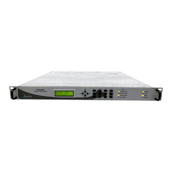
- Page 1 DM240XR High-Speed Digital Modulator Installation and Operation Manual TM120 Revision 1.1 Radyne Inc. • 3138 E. Elwood St. • Phoenix, AZ 85034 • (602) 437-9620 • Fax: (602) 437-4811 • www.radn.com...
- Page 3 Unless otherwise agreed, failure shall be deemed to have occurred no more than seven (7) working days before the first date on which Radyne Inc. receives a notice of failure. Under no circumstances shall any warranty exceed the period stated above unless expressly agreed to in writing by Radyne Inc.
- Page 4 Radyne Inc.’s liability for damages shall not exceed the payment, if any, received by Radyne Inc. for the unit or product or service furnished or to be furnished, as the case may be, which is the subject of claim or dispute.
- Page 5 DM240XR High-Speed Digital Modulator Preface Preface This manual provides installation and operation information for the Radyne DM240XR High- Speed Digital Modulator. This is a technical document intended for use by engineers, technicians, and operators responsible for the operation and maintenance of the DM240XR.
- Page 6 ©2006, Radyne Inc. This manual is proprietary to Radyne Inc. and is intended for the exclusive use of Radyne Inc.’s customers. No part of this document may in whole or in part, be copied, reproduced, distributed, translated or reduced to any electronic or magnetic storage medium without the express written consent of a duly authorized officer of Radyne Inc.
-
Page 7: Table Of Contents
DM240XR High-Speed Digital Modulator Table of Contents Table of Contents Section 1 Introduction .....................1-1 1.0 Description ......................1-1 Section 2 - Installation ....................2-1 2.0 Installation Requirements...................2-1 2.1 Unpacking ......................2-2 2.2 Removal and Assembly..................2-2 2.3 Mounting Considerations..................2-2 2.4 Modulator Checkout ...................2-2 2.4.1 Initial Power-Up....................2-3 Section 3 - Theory of Operation ................3-1... - Page 8 Table of Contents DM240XR High-Speed Digital Modulator 4.2.5 Monitor Menu Options and Parameters............4-16 4.2.6 Alarms Menu Options and Parameters............4-16 4.2.7 System Menu Options and Parameters............4-17 4.2.8 Test Menu Options and Parameters..............4-21 4.3 Remote Port User Interface................4-22 4.3.1 Protocol Structure ..................4-22 4.3.2 Protocol Wrapper ..................4-22...
- Page 9 7.9 Data Rates (DVB-S)....................7-5 7.9.1 Data Rates (DVB-S2) ..................7-7 Appendix A - Remote Operations ................A-1 A.0 DM240XR Opcode Command Set ..............A-1 A.1 Modulator Command Set .................. A-1 A.2 Detailed Command Descriptions............... A-3 Appendix B - SNMP MIB ................... B-1 Glossary........................G-1...
- Page 10 Table of Contents DM240XR High-Speed Digital Modulator TM120 – Rev. 1.1...
-
Page 11: Introduction
Introduction Introduction This chapter provides an overview of the DM240XR High-Speed Digital Modulator. The DM240XR will be referred to in this manual as “the DM240XR”, “the modulator”, or “the unit”. 1.0 Description The New Standard in Digital Modulator Performance Radyne’s DM240XR family of High-Speed Modulators is the ideal choice to meet the exacting standards of High Data-Rate Video, Internet and Fiber Restoral Satellite Applications. - Page 12 Introduction DM240XR High-Speed Digital Modulator TM120 – Rev. 1.1...
-
Page 13: Section 2 - Installation
1 RU mounting space (1.75 inches) vertically and 17 inches of depth. Including cabling, a minimum of 20-inches of rack depth is required. The rear panel of the DM240XR is designed to have power enter from the left and IF cabling enter from the right when viewed from the rear of the unit. -
Page 14: Unpacking
The DM240XR is designed for indoor applications only. The only tools required for rack mounting the DM240XR is a set of four rack mounting screws and an appropriate screwdriver. Rack mount brackets are an integral part of the cast front bezel of the unit and are not removable. -
Page 15: Initial Power-Up
Monitor/Control program. These power- up diagnostics show no results if successful. If a failure is detected, the Fault LED is illuminated. The initial field checkout of the DM240XR can be accomplished from the front panel, Terminal Port, Remote Port, or Ethernet Port. - Page 16 Installation DM240XR High-Speed Digital Modulator TM120 – Rev. 1.1...
-
Page 17: Section 3 - Theory Of Operation
RF Carrier produced from the Transmit IF Synthesizer Circuitry. Since the baseband processing is completely digital, many different variations of signal processing can be performed. Therefore, the DM240XR is one of the most flexible digital modulators available today. 3.1 DVB-S Operation The DVB-S version of the DM240XR complies with both EN300-421 and EN301-210 ETSI Specifications. -
Page 18: Dvb-S2-Bs-Nbc Operation
DM240XR High-Speed Digital Modulator 3.2 DVB-S2-BS-NBC Operation The DVB-S2-BS-NBC version of the DM240XR complies with the ETSI EN 302 307 V1.1.1 (2004-01) specification for non-backward compatible broadcast services. A block diagram of the signal flow is shown in Figure 3-2 below. - Page 19 DM240XR High-Speed Digital Modulator Theory of Operation TM120 – Rev. 1.1...
-
Page 20: Section 4 - User Interfaces
Terminal 4.1 Front Panel User Interface The front panel of the DM240XR allows for complete control and monitor of all DM240XR parameters and functions via a keypad, LCD display and status LEDs. The front panel layout is shown in Figure 4−1, showing the location and labeling of the front panel. -
Page 21: Front Panel Lcd Display
Depress <ENTER> again and re-enter the new parameters followed by <ENTER>. Following a valid input, the DM240XR will place the new setting into the nonvolatile SRAM making it available immediately and available the next time the unit is powered-up. - Page 22 DM240XR High-Speed Digital Modulator User Interfaces Table 4-3. Edit Mode Key Functions (Front Panel Only) ↑ ↓ ← → Parameter 0 – 9 ‘Clear’ & ‘Clear’ & ← → Type Fixed Point Changes Digit Toggles ± Toggles ± Moves Moves...
- Page 23 User Interfaces DM240XR High-Speed Digital Modulator Figure 4-2. DM240XR Main Programming Menu TM120 – Rev. 1.1...
- Page 24 If at any time the user wishes to abort the changes being made, depress <CLEAR> to begin again. Figure 4-3. Entering New Parameters 4.2 Front Panel Control Screen Menus The complete set of DM240XR Front Panel Control Screens is made up of Main Menus. Each Main Menus has several Option and Parameter Screens.
-
Page 25: Modulator Menu Options And Parameters
The first status line indicates the side of the RF switch that the DM240XR is attached (prime or backup). The second status line indicates if the output of the DM240XR is the active output of the RF switch (online) or inactive (offline). MONITOR... -
Page 26: Interface Menu Options And Parameters
DM240XR High-Speed Digital Modulator User Interfaces DATA RATE (BPS): Terrestrial Data Rate: Enter in 1 Bps increments from 1,000,000 to 238,000,000 BPS. SYMB RATE (SPS): Output Symbol Rate: Enter in 1 SPS increments from 1,000,000 to 68,000,000 Sps. SPECTRUM: {NORMAL, INVERTED} ROLL OFF: {0.35, 0.25, 0.20}... - Page 27 User Interfaces DM240XR High-Speed Digital Modulator BACKUP INPUT: {INTFC 1, INTFC 2, INTFC 3} Backup Input Select - Allows the user to designate the Backup Input in Redundancy Mode. An “(A)” indicates the active input. INTERFACE TYPE: {ASI, Advanced ASI, HSSI, M2P Parallel, DVB Parallel...
-
Page 28: Ethernet Interface (J1)
Normally, this clock is used to clock the data out of the data source and then return it to the SCTE input. The DM240XR is then set to SCTE mode eliminating any possible clock skew. Alternately, the data source can generate the SCTE clock internally and the SCT signal can be ignored. - Page 29 User Interfaces DM240XR High-Speed Digital Modulator MODE SELECTIONS: {UDP PACKETS, COP 3 RTP, or COP 3 RTP FEC UDP PACKETS - the modulator accepts generic UDP packets with seven MPEG packets encapsulated in each UDP datagram. COP 3 RTP - the modulator accepts seven MPEG packets encapsulated in a COP 3 compliant RTP datagram.
- Page 30 DM240XR High-Speed Digital Modulator User Interfaces PRIME ETHERNET: Scroll down to configure the IP selection for the prime UDP port PRIME IP ADDR: {XXX.XXX.XXX.XXX} Allows entry of the prime IP address to be used by the Ethernet Data Interface. This will be the source IP address for all Ethernet traffic generated by this interface.
- Page 31 User Interfaces DM240XR High-Speed Digital Modulator Backup Column FEC packets must arrive on Prime UDP port + 2 Backup Row FEC packets must arrive on Prime UDP port + 4 PROG ETH FLASH: {Press Clear} Used for field upgrades. To upgrade the EDI firmware, install the appropriate PCMCIA card, scroll to this menu, and press clear.
- Page 32 DM240XR High-Speed Digital Modulator User Interfaces PRIME COL FEC {Disabled, No Activity, Online Activity, Offline Activity} Disabled: FEC is not enabled (COP3 RTP FEC mode is not selected) No Activity: The prime port is not receiving any column FEC packets...
- Page 33 User Interfaces DM240XR High-Speed Digital Modulator BACKUP ROW FEC {No Activity, Online Activity, Offline Activity} Disabled: FEC is not enabled (COP3 RTP FEC mode is not selected) No Activity: The backup port is not receiving any row FEC packets Online Activity:...
-
Page 34: Rf Switch Menu Options And Parameters
Pressing ENTER causes the backup side of the RF switch to be selected as online. (BACKUP|PRIME) STATUS: {NORMAL, FAULT} This is the status of the other DM240XR connected to the RF switch. FAULT TEST: {NORMAL, FAULT} Asserts the fault signal to the RF switch for testing purposes. -
Page 35: Monitor Menu Options And Parameters
User Interfaces DM240XR High-Speed Digital Modulator 4.2.5 Monitor Menu Options and Parameters EVENTS: Event Buff: Display/Clear logged events and faults. ERASE EVENTS: Clear Events: Clear all logged events and faults from the event buffer. +5V SUPPLY: Display the currently measured +5 VDC power supply. -
Page 36: System Menu Options And Parameters
DM240XR High-Speed Digital Modulator User Interfaces LATCHED ALARMS (Menu): This menu duplicates the Current Alarm Menu, but displays Latched Alarms instead of Current Alarms. TX MAJOR (Menu) SCT PLL: {PASS/FAIL} OVERSAMPLE PLL: {PASS/FAIL} SYNTH PLL: {PASS/FAIL} SSYS REF PLL: {PASS/FAIL}... - Page 37 User Interfaces DM240XR High-Speed Digital Modulator Remote Port (Menu) ADDRESS: Multi-Drop Address: Enter the address for computer control from 32 to 255. BAUD RATE: {150, 300, 600, 1200, 2400, 4800, 9600, 19200, 38400} Remote port baud rate for Terminal and Computer Mode.
- Page 38 DM240XR High-Speed Digital Modulator User Interfaces ROUTER IP ADDR: {XXX.XXX.XXX.XXX} The IP Address of the Local Network Router. If a router is present on the local network, this address must be consistent with the IP Mask and the subnet of the modem.
- Page 39 {VT100, VIEWPOINT, WYSE50} BAUD RATE: {300, 600, 1200, 2400, 4800, 9600, 19200, 38400, 57600} Allows the user to enter the Terminal Baud Rate. HW/FW CONFIG (menu) DM240XR: {"Status Only"} Displays the DM240XR feature level (e.g. Series 400) 4-20 TM120 – Rev. 1.1...
-
Page 40: Test Menu Options And Parameters
DM240XR High-Speed Digital Modulator User Interfaces FIRMWARE REV: {"Status Only"} Displays the Firmware revision level. M&C REV: {"Status Only"} Displays the Monitor and Control revision level. MAIN BOARD: {sub-menu} MAIN BOARD (menu) PC NUMBER: {"Status Only"} ASSEMBLY #: {"Status Only"} SERIAL NUMBER: {"Status Only"}... -
Page 41: Remote Port User Interface
DM240XR High-Speed Digital Modulator 4.3 Remote Port User Interface The Remote Port of the DM240XR allows for complete control and monitor functions via an RS-485 Serial Interface. Control and status messages are conveyed between the DM240XR and the subsidiary modems, and the host computer using packetized message blocks in accordance with a proprietary communications specification. - Page 42 DM240XR High-Speed Digital Modulator User Interfaces <SYN> - the message format header character, or ASCII sync character, that defines the beginning of a message. The <SYN> character value is always 16h. <BYTE COUNT> - the Byte Count is the number of bytes in the <DATA> field, ranging from 0 through TBD.
-
Page 43: Frame Description And Bus Handshaking
User Interfaces DM240XR High-Speed Digital Modulator Thus, the checksum is 00000101b; which is 05h or 5 decimal. Alternative methods of calculating the checksum for the same message frame are: 00h + 02h + F0h + 2Ah + 09h + 00h + 03h + DFh + FEh = 305h. -
Page 44: Global Response Operational Codes
Global response Opcodes are common responses, issued to the M&C computer or to another device, that can originate from and are interpreted by all Radyne equipment in the same manner. These are summarized as follows (all Opcode values are... -
Page 45: Collision Avoidance
User Interfaces DM240XR High-Speed Digital Modulator 4.3.5 Collision Avoidance When properly implemented, the physical and logical devices and ID addressing scheme of the COMMSPEC normally precludes message packet contention on the control bus. The importance of designating unique IDs for each device during station configuration cannot be overemphasized. -
Page 46: Software Compatibility
Volatile Section. If the remote M&C is not aware of the newly added features to the Radyne product, it should disregard the parameters at the end of the Non-Volatile Section and index to the start of the Volatile Section. -
Page 47: Rllp Summary
Refer to Appendix A for Modem Remote Communications. 4.4 Ethernet Port User Interface The Ethernet Port of the DM240XR allows for complete control and monitoring of all DM240XR parameters and functions via a 10 Base-T or 100 Base-T Ethernet Connection. -
Page 48: The Management Information Base (Mib)
SMI. Radyne ComStream Corporation’s Private Enterprise Number is 2591. Other products are added to Radyne ComStream Corporation’s subtree as they become remotely manageable through SNMP. - Page 49 User Interfaces DM240XR High-Speed Digital Modulator Figure 4-4a. Object Identifiers in the Management Information Base (Figure 1 of 2) Figure 4-4b. Object Identifiers in the Management Information Base (Figure 2 of 2) 4-30 TM120 – Rev. 1.1...
-
Page 50: Terminal Port User Interface
Refer to Appendix B for the MIB 4.7 Terminal Port User Interface The Terminal Port of the DM240XR allows for complete control and monitoring of all DM240XR parameters and functions via an RS-232 Serial Interface. Terminal mode communications and protocol is set from the front panel control by setting the “Control Mode”... - Page 51 User Interfaces DM240XR High-Speed Digital Modulator Figure 4-6. Modulator Menu Figure 4-7. Event Log Menu 4-32 TM120 – Rev. 1.1...
- Page 52 DM240XR High-Speed Digital Modulator User Interfaces Figure 4-8. Multi-PIIC Control Menu Figure 4-9. Test Control Menu TM120 – Rev. 1.1 4-33...
- Page 53 User Interfaces DM240XR High-Speed Digital Modulator Figure 4-10. TCP/IP/SNMP Control Menu Figure 4-11. Front Panel/RLLP/Terminal Control Menu 4-34 TM120 – Rev. 1.1...
- Page 54 DM240XR High-Speed Digital Modulator User Interfaces Figure 4-12. RF Switch Control Menu Figure 4-13. Ethernet Data Switch Menu Note: Only displayed when the Ethernet Data Interface is installed. TM120 – Rev. 1.1 4-35...
- Page 55 User Interfaces DM240XR High-Speed Digital Modulator 4-36 TM120 – Rev. 1.1...
-
Page 56: Section 5 - Rear Panel Interfaces
5.0 DM240XR Connections All DM240XR connections are made to labeled connectors located on the rear of the unit. Any connection interfacing to the DM240XR must be the appropriate mating connector. DM240XR Optional Data Interfaces are shown in Figures 5-1b –... - Page 57 Rear Panel Interfaces DM240XR-DVB High-Speed Digital Modulator Figure 5-1e. DM240XR Rear Panel Connectors (Ethernet) Figure 5-1f. DM240XR Rear Panel Connectors (DVB/M2P RS422 PARA) Figure 5-1g. DM240XR Rear Panel Connectors (DVB/LVDS PARA) Figure 5-1h. DM240XR Rear Panel Connectors (HSSI) TM120 - Rev. 1.1...
-
Page 58: Ac Power
Remove the upgrade Compact Flash Card. Reinstall the Compact Flash Card that was removed in Step 2. If the red Fault LED illuminates, contact the Radyne ComStream Customer Service Department. The loaded features will be available the next time the unit is powered on. -
Page 59: Firmware Update
Rear Panel Interfaces DM240XR-DVB High-Speed Digital Modulator 5.2.2 Firmware Update To upgrade the firmware, a new Compact Flash Card with the upgraded firmware is required for each unit. 1. Power off the unit. 2. Remove Compact Flash. 3. Install new Compact Flash. -
Page 60: Remote Port (I/O)
DM240XR-DVB High-Speed Digital Modulator Rear Panel Interfaces 5.5 Remote Port (I/O) The Remote Port Interface (J4) can be used for the monitor & control functions of the unit. The physical interface is a female 9-Pin D-Sub Connector. This bi-directional port complies with RS-485 Electrical Specifications. -
Page 61: If Output Port (J9 & J10)
5.8.1 Output Monitor Port (J9) The output monitor port on the DM240XR is an SMA female connector. The monitor is a sample of the output frequency that is –20dBc +/-5dB from the output frequency power level. RF Switch Control (J2) Each modulator has a 9-pin D-sub connector for the switch. -
Page 62: Built In Asi/Advanced Asi Interface (J7)
DM240XR-DVB High-Speed Digital Modulator Rear Panel Interfaces nBackup_Sel Forces On-Line output to Backup Output Local Fault Fault output of modulator Output Distant Fault State of distant modulator Input Switch-State Switch state monitor. Input Logic '1' = Prime Online 5.10 Built in ASI/Advanced ASI Interface (J7) The “Built In”... -
Page 63: Asi Piic
Rear Panel Interfaces DM240XR-DVB High-Speed Digital Modulator 5.11.1 ASI PIIC This interface supports two terrestrial interface types. 5.11.1.1 ASI (Asynchronous Serial Interface) The ASI interface is supported on the BNC Connector (Figure 5-1b). The interface complies with DVB ASI Electrical Specifications. The maximum data rate is 216 Mbps. -
Page 64: Dvb (Parallel, Rs-422)
DM240XR-DVB High-Speed Digital Modulator Rear Panel Interfaces Input Input Input Input Input Input Input Input Input Input Input Input Input Input Not Connected 5.11.3.2 DVB (Parallel, RS-422) The DVB Interface is also supported on the DB-25 Female Connector. It complies with RS-422 Electrical Specifications. -
Page 65: Parallel Lvds Interface
Rear Panel Interfaces DM240XR-DVB High-Speed Digital Modulator System GND Ground D7 - Input D6 - Input D5 - Input D4 - Input D3 - Input D2 - Input D1 - Input D0 - Input DVALID - Input SYNC - Input 5.11.4 Parallel LVDS Interface... -
Page 66: Ethernet 100/1000 Base-T Interface
DM240XR-DVB High-Speed Digital Modulator Rear Panel Interfaces 14 - 18 39 – 43 5 Ancillary to Reserved Input Signal Ground 20 - 23 45 - 48 4 Ancillary Reserved Output from DCE Test Mode Output- 5.11.6 Ethernet 100/1000 Base-T Interface The PIIC Ethernet Data Interface (Figure 5-1e) is a full duplex 100/1000 BaseT supported by an RJ45 connector . - Page 67 Rear Panel Interfaces DM240XR-DVB High-Speed Digital Modulator 5-12 TM120 - Rev. 1.1...
-
Page 68: Section 6 - Maintenance And Troubleshooting
The DM240XR modulator requires no periodic field maintenance procedures. Should a unit be suspected of a defect in field operations after all interface signals are verified, the correct procedure is to replace the unit with another known working DM240XR. If this does not cure the problem, wiring or power should be suspect. - Page 69 Maintenance and Troubleshooting DM240XR High-Speed Digital Modulator TM120 – Rev. 1.1...
-
Page 70: Section 7 - Technical Specifications
DM240XR High-Speed Digital Modulator Technical Specifications Technical Specifications 7.0 Introduction This section defines the technical performance parameters and specifications for the DM240XR Digital Modulator. 7.1 IF Specification Tx IF: 50 to 90 MHz, 100 to 180 MHz (70/140 MHz), 950 to 2050 MHz (L-Band) - Page 71 Technical Specifications DM240XR High-Speed Digital Modulator Baseband Roll-Off: Square Root Raised Cosine 0.35 (BPSK, QPSK, 8PSK, 16QAM) 0.25 (8PSK, 16QAM) 0.20 (BPSK, QPSK) Terrestrial Input Clock Accuracy: 400 ppm (Maximum) Test Pattern: Internal 2 -1 and 2 -1 Pseudo-Random Number Generators 7.2.2 DVB-S2-CCM (CCM - Normative)
-
Page 72: Interface Types Available (Piic)
DM240XR High-Speed Digital Modulator Technical Specifications 7.2.3 DVB-S2-ACM (Normative Features with Single Transports streams) Compliance ETSI EN 302 307 v1.1.1 (normative) Modulation Types: QPSK, (8PSK, 16APSK & 32APSK Optional) Transport Streams Single MPEG Packetized Transport Streams Data Rate: 1 to 54 Mbps in 1 bps steps (QPSK) 2 to 118 Mbps in 1 bps steps (8PSK) 2.6 to 160 Mbps in 1 bps steps (16APSK) -
Page 73: Monitor And Control
Technical Specifications DM240XR High-Speed Digital Modulator 7.4 Monitor and Control Interface: Serial RS-485 and RS-232, Ethernet 10/100 Base-T Parameters Controlled: IF Frequency IF Output Level IF Output On/Off Modulation Type FEC Rate Spectral Inversion Data Rate Symbol Rate Roll-Off Interface Type... -
Page 74: Dvb-S2 Series Configuration
DM240XR High-Speed Digital Modulator Technical Specifications 7.8.1 DVB-S2 Series Configuration Series 100: 1-10 Msps, QPSK Series 200: 1-45 Msps, QPSK Series 300: 1-45 Msps, QPSK/8PSK Series 400: 1 to 45 Msps, QPSK/8PSK/16APSK/32APSK Series 500: 1 to 45 Msps, QPSK/8PSK/16APSK/32APSK Data Rates (DVB-S) All Data Rates in Mbps. - Page 75 Technical Specifications DM240XR High-Speed Digital Modulator DVB-S Series 300 Modulation MPEG Unframed Minimum Maximum Minimum Maximum QPSK 1000000 41470588 1000000 45000000 QPSK 1228758 55294118 1333333 60000000 QPSK 1382353 62205882 1500000 67500000 QPSK 1535948 69117647 1666667 75000000 QPSK 1612745 72573529 1750000...
-
Page 76: Data Rates (Dvb-S2)
DM240XR High-Speed Digital Modulator Technical Specifications 7.9.1 Data Rates (DVB-S2) DVB-S2 Series 100 Modulation MPEG Minimum Maximum QPSK 1000000 6564481 QPSK 1000000 7894121 QPSK 1000000 9888581 QPSK 1188304 11883041 QPSK 1322253 13222530 QPSK 1487473 14874731 QPSK 1587196 15871961 QPSK 1654663... - Page 77 Technical Specifications DM240XR High-Speed Digital Modulator DVB-S2 Series 300 Modulation MPEG Minimum Maximum QPSK 1000000 44498615 QPSK 1188304 53473684 QPSK 1322253 59501385 QPSK 1487473 66936288 QPSK 1587196 71423823 QPSK 1654663 74459834 QPSK 1766451 79490305 QPSK 9/10 1788612 80487535 8PSK 1779991...
- Page 78 DM240XR High-Speed Digital Modulator Technical Specifications 16APSK 2637201 118674033 16APSK 2966728 133502762 16APSK 3165623 142453039 16APSK 3300184 148508287 16APSK 3523143 158541436 16APSK 9/10 3567342 160530387 *Normal Frame size (64800) no pilot insertion DVB-S2 Series 500 Modulation MPEG Minimum Maximum QPSK...
- Page 79 Technical Specifications DM240XR High-Speed Digital Modulator 7-10 TM120 – Rev. 1.1...
-
Page 80: Appendix A - Remote Operations
DM240XR High-Speed Digital Modulator Appendix A Remote Operations When new features are added to Radyne Inc. equipment, the control parameters are appended to the end of the Non-Volatile Section of the Remote Communications Specification, and status of the features, if any, are added at the end of the Volatile Section. - Page 81 Appendix A DM240XR High-Speed Digital Modulator Query IPSat Control PID (w/IPSat interface card only) 2458h Query IPSat Enable (w/IPSat interface card only) 2459h Query IPSat User Data Rate (w/IPSat interface card only) 245Ah Query PCR Restamping 245Bh Query Multi-PIIC Configuration (w/Multi-PIIC interface card only)
-
Page 82: Detailed Command Descriptions
DM240XR High-Speed Digital Modulator Appendix A Command RF Switch Fault Test (w/RF Switch hardware only) 2F41h Command RF Switch Activate Side (w/RF Switch hardware 2F42h only) A.2 Detailed Command Descriptions Opcode: <2400h> (Query Mod All) Query a Modulator's Configuration and Status Query Response <1>... - Page 83 Appendix A DM240XR High-Speed Digital Modulator <1> Tx Interface 0 = Serial, Type 1 = Parallel, 2 = ASI_Norm, 3 = ASI_Null, 4 = G.703E3, 5 = G.703T3, 6 = G.703STS-1, 7 = HSSI, 8 = Parallel DVB, 9 = Parallel M2P,...
- Page 84 DM240XR High-Speed Digital Modulator Appendix A <1> Common Fault Bit 0 = -12 V Alarm Mask Bit 1 = +12 V Alarm Bit 2 = +5 V Alarm Bit 3 = Spare Bit 4 = Spare Bit 5 = Spare...
- Page 85 Appendix A DM240XR High-Speed Digital Modulator <1> Redundancy Without Multi-PIIC Card or Manual Multi-PIIC Mode: Mode With Multi-PIIC Card: 0 = Force Prime, 1 = Force Backup, 2 = Manual Revert, 3 = Auto-Revert <1> Prime PIIC Slot Without Multi-PIIC Card: With Multi-PIIC Card: 1 –...
- Page 86 DM240XR High-Speed Digital Modulator Appendix A <1> Minor Alarm Bit 0 = Spare Bit 1 = Loss Terrestrial Clock Bit 2 = Loss Terrestrial Data Bit 3 = FIFO Error Bit 4 = Spare Bit 5 = Terrestrial Framing Error...
- Page 87 Appendix A DM240XR High-Speed Digital Modulator <2> Reserved <2> Reserved <1> Last Rate Status 0 = Symbol Rate, 1 = Data Rate <1> Active PIIC Slot Without Multi-PIIC Card: With Multi-PIIC Card: 1 – 3 <1> Slot 1 PIIC Type...
- Page 88 DM240XR High-Speed Digital Modulator Appendix A Bit 3 = Slot 3 Activity Opcode: <2405h> Query a Modulator’s Latched Alarms Query response <1> Latched Major Bit 0 = Spare Alarm Bit 1 = Transmit Oversample PLL Lock Bit 2 = FPGA Config Error...
- Page 89 Appendix A DM240XR High-Speed Digital Modulator Bit 7 = Spare 0 = Pass, 1 = Fail <1> Common Fault Bit 0 = -12 V Alarm Bit 1 = +12 V Alarm Bit 2 = +5 V Alarm Bit 3 = Spare...
- Page 90 DM240XR High-Speed Digital Modulator Appendix A <1> Latched Major Bit 0 = Spare Alarm Bit 1 = Transmit Oversample PLL Lock Bit 2 = FPGA Config Error Bit 3 = IF Synthesizer PLL Lock Bit 4 = External Reference PLL Lock...
- Page 91 Appendix A DM240XR High-Speed Digital Modulator <1> Slot 1 PIIC Type Without Multi-PIIC Card: 0x13 = ASI <1> Slot 2 PIIC Type With Multi-PIIC Card: 0x93 = ASI 0x94 = RS422 0x95 = LVDS Parallel 0x96 = HSSI 0x9C = DirecTV (PECL)
- Page 92 DM240XR High-Speed Digital Modulator Appendix A <1> 1 – 31 <1> Hour 0 – 23 <1> Minute 0 – 59 <1> Second 0 – 59 Opcode: <2414h> Query Firmware Part/Rev <16> Firmware ASCII null terminated string Part/Rev Opcode: <2456h> Query AASI NULL PID <2>...
- Page 93 Appendix A DM240XR High-Speed Digital Modulator Opcode: <245Ch> Query Multi-PIIC Configuration <1> Multi-PIIC Mode 1 = Manual, 2 = Redundancy <1> Redundancy 0 = Force Prime, Mode 1 = Force Backup, 2 = Manual Revert, 3 = Auto-Revert <1> Prime PIIC Slot 1 –...
- Page 94 DM240XR High-Speed Digital Modulator Appendix A Opcode: <2601h> Command a Modulator's Configuration <4> IF Frequency Binary Value, units Hz in 100Hz steps. 50000000Hz to 180000000Hz 70/140 950000000Hz to 2050000000Hz L-Band <2> Reserved <4> Data Rate Binary Value, 1 bps Steps (See note at the end of this command.)
- Page 95 Appendix A DM240XR High-Speed Digital Modulator <1> Tx Interface 0 = Serial, Type 1 = Parallel, 2 = ASI_Norm, 3 = ASI_Null, 4 = G.703E3, 5 = G.703T3, 6 = G.703STS-1, 7 = HSSI, 8 = Parallel DVB, 9 = Parallel M2P,...
- Page 96 DM240XR High-Speed Digital Modulator Appendix A <1> Common Fault Bit 0 = -12 V Alarm Mask Bit 1 = +12 V Alarm Bit 2 = +5 V Alarm Bit 3 = Spare Bit 4 = Spare Bit 5 = Spare...
- Page 97 Appendix A DM240XR High-Speed Digital Modulator <1> Redundancy Without Multi-PIIC Card or Manual Multi-PIIC Mode: Mode With Multi-PIIC Card: 0 = Force Prime, 1 = Force Backup, 2 = Manual Revert, 3 = Auto-Revert <1> Prime PIIC Slot Without Multi-PIIC Card: With Multi-PIIC Card: 1 –...
- Page 98 DM240XR High-Speed Digital Modulator Appendix A DM240XR Clock Source Selection Matrix Interface Type InClk Source OutClk Source RS-422 Serial SCT or SCTE SCT Only G.703 (E3, T3, STS-1) SCTE Only SCT, SCTE, or None HSSI SCT or SCTE SCT Only...
- Page 99 Appendix A DM240XR High-Speed Digital Modulator Opcode: <2602h> Command a Modulator's Frequency <4> Frequency Binary Value, units Hz in 100Hz steps. 50000000Hz to 180000000Hz 70/140 950000000Hz to 2050000000Hz L-Band (This command will cause the carrier to turn off). Opcode: <2604h>...
- Page 100 DM240XR High-Speed Digital Modulator Appendix A Opcode: <2619h> Command DM240 Network Spec <1> Network Spec 0 = DVB-S 9 = DirecTV 11 = DVB-S2-CCM 13 = DirecTV AMC/NBC 15 = DVB-S2-CCM Opcode: <261Bh> Command a Modulator's External Reference Frequency <4>...
- Page 101 Appendix A DM240XR High-Speed Digital Modulator Opcode: <2643h> Command a Modulator’s Symbol Rate <1> Symbol Rate Binary Value, 1bps Steps (This command will cause the carrier to turn off. Opcode: <2656h> Command AASI NULL PID <2> 0x0010 - 0x1FFF Opcode: <2657h>...
- Page 102 DM240XR High-Speed Digital Modulator Appendix A Opcode: <2C05h> Command Set Date <1> Year 00 – 99 <1> Month 1 – 12 <1> 1 – 31 Opcode: <2C06h> Command Set Time and Date <1> Year 00 – 99 <1> Month 1 – 12 <1>...
- Page 103 Appendix A DM240XR High-Speed Digital Modulator A-24 TM120 – Rev. 1.1...
-
Page 104: Appendix B - Snmp Mib
FROM RFC-1212 DisplayString FROM RFC1213-MIB; -- groups in Radyne specific MIB radyne OBJECT IDENTIFIER ::= { enterprises 2591 } dvb3030 OBJECT IDENTIFIER ::= { radyne 1 } radSNMP_Mod_NV_Status OBJECT IDENTIFIER ::= { dvb3030 1 } radSNMP_Mod_Status OBJECT IDENTIFIER ::= { dvb3030 2 }... - Page 105 Appendix B DM240XR High-Speed Digital Modulator piicInSerialRs422( '9B'h), piicInDirecTVAmc( '9C'h), piicInGigEthernet( '9D'h), piicOutAsi( 'D3'h), none( 'ff'h) RadRadioFreqHz ::= TEXTUAL-CONVENTION DISPLAY-HINT "d" STATUS current DESCRIPTION "Radio Frequency in Hz." SYNTAX OCTET STRING radCarrierControl OBJECT-TYPE SYNTAX INTEGER { off(0), on(1) ACCESS read-write...
- Page 106 DM240XR High-Speed Digital Modulator Appendix B STATUS optional DESCRIPTION "Selects symbol rate mode. This can only be modified if the factory configuration is set to both variable and fixed. This is obsolete." ::= { radSNMP_Mod_NV_Status 6 } radStrapCode OBJECT-TYPE SYNTAX INTEGER (0..65535)
- Page 107 Appendix B DM240XR High-Speed Digital Modulator ACCESS read-write STATUS current DESCRIPTION "Selects the frame transport stream input type. Note: Changing the framing mode will affect the symbol rate and/or data rate. See note at the end of this section." ::= { radSNMP_Mod_NV_Status 10 }...
- Page 108 DM240XR High-Speed Digital Modulator Appendix B "Selects the various interface types. The following choices are not supported: none(10), oc3(13), stm1(14) Note: Selecting interface types Parallel DVB, Parallel M2P, Serial, DirecTv or HSSI will force the outclock selection to SCT. Selecting interface type ASI Norm or ASI Null causes the outclock selection to be forced to None.
- Page 109 Appendix B DM240XR High-Speed Digital Modulator Reserved" ::= { radSNMP_Mod_NV_Status 19 } radReedsolomon OBJECT-TYPE SYNTAX INTEGER { disable(0), enable(1) ACCESS read-write STATUS current DESCRIPTION "Enables the ReedSolomon encoder. Reserved" ::= { radSNMP_Mod_NV_Status 20 } radScramblerControl OBJECT-TYPE SYNTAX INTEGER { disable(0),...
- Page 110 DM240XR High-Speed Digital Modulator Appendix B Bit 5 = Composite PLL Lock Bit 6 = Symbol PLL Lock " ::= { radSNMP_Mod_NV_Status 25 } radMinorAlarmMask OBJECT-TYPE SYNTAX INTEGER (0..255) ACCESS read-write STATUS current DESCRIPTION "Minor Alarm mask: A bit field. 0 = MASKED, 1 = UNMASKED...
- Page 111 Appendix B DM240XR High-Speed Digital Modulator ACCESS read-write STATUS optional DESCRIPTION "Provides entry of Tx circuit identifier. Circuits can be given up to 11 character alphanumeric identity such as LINK1. Not implemented." ::= { radSNMP_Mod_NV_Status 30 } radControlMode OBJECT-TYPE SYNTAX INTEGER {...
- Page 112 DM240XR High-Speed Digital Modulator Appendix B DESCRIPTION "Allows the modulator to behave with symbol rate or data rate precedence based on the selection. See rate control notes." ::= { radSNMP_Mod_NV_Status 35 } radClearLatchedAlarms OBJECT-TYPE SYNTAX INTEGER { clearAlarms(1) ACCESS read-write...
- Page 113 Appendix B DM240XR High-Speed Digital Modulator ::= { radSNMP_Mod_NV_Status 41 } -- radRadioFrequencyHz OBJECT-TYPE SYNTAX RadRadioFreqHz (SIZE (8)) ACCESS read-write STATUS current DESCRIPTION "Selects RF frequency in Hz." ::= { radSNMP_Mod_NV_Status 42 } -- radLoFrequencyHz OBJECT-TYPE SYNTAX RadRadioFreqHz (SIZE (8))
- Page 114 DM240XR High-Speed Digital Modulator Appendix B STATUS current DESCRIPTION "Enables/disables the physical layer scrambler. The modulator is considered in a test mode when the scrambler is bypassed." ::= { radSNMP_Mod_NV_Status 47 } radInnerFecBypass OBJECT-TYPE SYNTAX INTEGER { normal(0), bypassed(1) ACCESS read-write...
- Page 115 Appendix B DM240XR High-Speed Digital Modulator ::= { radSNMP_Mod_NV_Status 52 } radPhaseNoiseProfileIndex OBJECT-TYPE SYNTAX INTEGER (1..16) ACCESS read-write STATUS current DESCRIPTION "Selects the phase noise profile." ::= { radSNMP_Mod_NV_Status 53 } radPlHeaderScramblerSeqIndex OBJECT-TYPE SYNTAX INTEGER (0..2000) ACCESS read-write STATUS current DESCRIPTION "Selects the directv physical layer header scrambler...
- Page 116 DM240XR High-Speed Digital Modulator Appendix B ::= { radSNMP_Mod_NV_Status 59 } radTerrEthRevert OBJECT-TYPE SYNTAX INTEGER { manual(0), auto(1) ACCESS read-write STATUS current DESCRIPTION "Selects the backup mode for the Gig Ethernet card." ::= { radSNMP_Mod_NV_Status 60 } radTerrEthBkupDly OBJECT-TYPE SYNTAX INTEGER (1..20)
- Page 117 ACCESS read-write STATUS current DESCRIPTION "Selects the MAC address for the Gig Ethernet card." ::= { radSNMP_Mod_NV_Status 68 } ---------------------------------------------------------------------------- -- Status information out of Radyne specific MIB radMajorAlarmStatus OBJECT-TYPE SYNTAX INTEGER (0..255) ACCESS read-only STATUS current DESCRIPTION "Major Alarm status: A bit field.
- Page 118 DM240XR High-Speed Digital Modulator Appendix B radLatchedMinorAlarmStatus OBJECT-TYPE SYNTAX INTEGER (0..255) ACCESS read-only STATUS current DESCRIPTION "Minor Alarm latched status: A bit field. 0 = PASS, 1 = FAIL Bit 1 = Terrestrial clock activity detect Bit 2 = Tx data activity detect...
- Page 119 Appendix B DM240XR High-Speed Digital Modulator ::= { radSNMP_Mod_Status 11 } radFactoryConfiguration OBJECT-TYPE SYNTAX INTEGER (0..65535) ACCESS read-only STATUS optional DESCRIPTION "A bit field that shows the factory configuration options. 0=No, 1=Yes. Bit 0 = Serial Interface Present Bit 1 = Parallel Interface...
- Page 120 DM240XR High-Speed Digital Modulator Appendix B ::= { radPiicSlotStatusTable 1 } -- RadPiicSlotStatusEntry ::= SEQUENCE { radPiicSlotStatusIndex INTEGER, radPiicSlotCardType RadInterfaceCardType, radPiicSlotClockActivity INTEGER, radPiicSlotDataActivity INTEGER -- radPiicSlotStatusIndex OBJECT-TYPE SYNTAX INTEGER ACCESS not-accessible STATUS current DESCRIPTION "Index for radPiicSlotStatusTable." ::= { radPiicSlotStatusEntry 1 }...
- Page 121 Appendix B DM240XR High-Speed Digital Modulator radRfSwitchConnectorSide OBJECT-TYPE SYNTAX INTEGER { primary(1), backup(2) ACCESS read-only STATUS current DESCRIPTION "Indicates the side of the RF switch to which the modulator is connected." ::= { radSNMP_Mod_Status 19 } radTerrEthPortStatus OBJECT-TYPE SYNTAX INTEGER {...
- Page 122 DM240XR High-Speed Digital Modulator Appendix B SYNTAX INTEGER { disabled(0), no_activity(1), online_activity(2), offline_activity(3) ACCESS read-only STATUS current DESCRIPTION "Shows the backup data activity of the Gig Ethernet card." ::= { radSNMP_Mod_Status 24 } radTerrEthActBackupCol OBJECT-TYPE SYNTAX INTEGER { disabled(0), no_activity(1),...
- Page 123 Appendix B DM240XR High-Speed Digital Modulator radTerrEthClrStats OBJECT-TYPE SYNTAX INTEGER { toggle0(0), toggle1(1) ACCESS read-write STATUS current DESCRIPTION "Clears the Gig Ethernet card statistics." ::= { radSNMP_Mod_Status 31 } B-20 TM120 – Rev. 1.1...
- Page 124 DM240XR High-Speed Digital Modulator Appendix B TM120 – Rev. 1.1...
-
Page 125: Glossary
DM240XR High-Speed Digital Modulator Glossary Glossary Ampere Alternating Current Analog to Digital Converter Automatic Gain Control Alarm Indication System. A signal comprised of all binary 1s. AMSL Above Mean Sea Level ANSI American National Standards Institute ASCII American Standard Code for Information Interchange... - Page 126 Glossary DM240XR High-Speed Digital Modulator Celsius CATS Computer Aided Test Software CA/xxxx Cable Assembly CD-ROM Compact Disk – Read Only Memory Clock Centimeter Common Central Processing Unit Cyclic Redundancy Check. A system of error checking performed at the transmitting and receiving stations.
- Page 127 DM240XR High-Speed Digital Modulator Glossary Fahrenheit Frame Acquisition Sync. A repeating series bits, which allow acquisition of a frame. Federal Communications Commission Forward Error Correction FIFO First In, First Out FPGA Field Programmable Gate Arrays Firmware Force of Gravity Gigahertz...
- Page 128 Glossary DM240XR High-Speed Digital Modulator Kbps Kilobits per Second KBps Kilobytes per Second Kilogram Kilohertz Ksps Kilosymbols per Second Liquid Crystal Display Light Emitting Diode Local Oscillator Milliampere Mbps Megabits per Second MFAS Multi-Frame Acquisition Sync. See FAS. Megahertz Management Information Base...
- Page 129 Receive (Receiver) Receive Data Reed-Solomon Coding. Reed-Solomon codes are block-based error correcting codes with a wide range of applications in digital communications and storage. Satellite Control Channel. A Radyne ComStream satellite format. Sequential SYNC Synchronize To Be Designed or To Be Determined...
- Page 130 Glossary DM240XR High-Speed Digital Modulator W X Y Z Watt Misc. µs Microsecond 16QAM 16 Quadrature Amplitude Modulation 8PSK 8 Phase Shift Keying TM120 – Rev. 1.1...
Need help?
Do you have a question about the DM240XR and is the answer not in the manual?
Questions and answers