Table of Contents
Advertisement
Quick Links
Download this manual
See also:
Owner's Manual
Advertisement
Table of Contents

Related Manuals for moon 650D

Summary of Contents for moon 650D
- Page 1 Owner’s Manual MOON Evolution Series 650 D 32-bit Digital-to-Analog Converter / CD Transport...
-
Page 2: Important Safety Instructions
MOON 650 D Digital-to-Analog Converter / CD Transport Important Safety Instructions Read these instructions. Keep these instructions. Heed all warnings. Follow all instructions. Do not use this apparatus near water. Clean only with a dry cloth. Do not block ventilation openings. Install in accordance with the manufacturer’s instructions. - Page 3 To prevent shock hazard, all three connections must ALWAYS be used. Connect the MOON 650D only to an AC source of the proper voltage; Both the shipping box and rear panel serial number label will indicate the correct voltage. Use of any other voltage will likely damage the unit and void the warranty AC extension cords are NOT recommended for use with this product.
-
Page 4: Table Of Contents
MOON 650 D Digital-to-Analog Converter / CD Transport Table of Contents Congratulations ..........5 Unpacking and Warnings ........5 Introduction ........... 6 Installation & Placement ........6 Front Panel Controls ........7 Rear Panel Connections ........9 SimLink™ ............10 Operating the 650D ........10 Remote Control Operation .......11... -
Page 5: Congratulations
The performance of your 650D will continue to improve during the first 400 hours of listening. This is the result of a “break- in” period required for the numerous high quality electronic parts used throughout this DAC / CD Transport. -
Page 6: Introduction
DAC / CD Transport’s performance and reliability. If the surface you have chosen isn’t perfectly level, each of the four (4) cones on your 650D are height adjustable; carefully using your fingers, you can either raise each leg by turning the cone underneath clockwise, or lower each leg by turning it counterclockwise.We strongly recommend that you leave these cones mounted to the component at all times for reasons... -
Page 7: Front Panel Controls
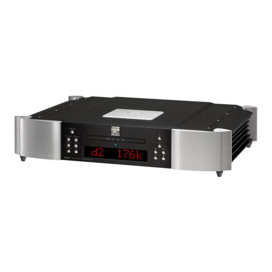
(or the total number of tracks in stop mode) and corresponding time information. The “Standby” button disengages the transport mechanism from the rest of the 650D’s circuitry and turns off the digital display. However, when in “Standby” mode, all digital and analog audio circuitry remains powered up to help maintain optimal performance. - Page 8 When the signal cannot be locked onto, “---- ” remains in the display window. The MOON 650D is capable of processing an external digital input signal at one of the following six (6) different sampling rates: 44.1kHz, 48.0 kHz, 88.2kHz, 96 kHz, 176.4kHz and 192kHz.
-
Page 9: Rear Panel Connections
SimLink for more details. Your MOON 650D DAC / CD Transport has a 1/8” mini jack input for use with aftermarket infrared remote control receivers. The “IR in” connector is located immediately to the right of the “SimLink” connectors. -
Page 10: Simlink
SimLink™ chain; no one particular component operates as the main communications controller. In the event that you are using your MOON 650D with an older MOON product such as a P-7, P-8 or i-7, you will need to update the software of the older product to allow for complete SimLink™... -
Page 11: Remote Control Operation
650D’s four (4) digital inputs - “D1”, “D2”, “D3” and “D4” - and the internal CD transport (as opposed to the ‘Input’ button located on the 650D’s front panel which only allows for forward scrolling). -
Page 12: Balanced Operation
For example, when one conductor is carrying a signal of +4 Volts, the other will be carrying a signal of –4 Volts. When these two inverted signals on a balanced line are output from the MOON 650D, any noise picked up by the interconnect will be eliminated since a differential circuit amplifies only the difference between these two signals: Noise on a balanced interconnect will be equal on both conductors and therefore not be processed. -
Page 13: Specifications
Balanced Pin Assignment: Pin 1........ Ground Pin 2........ Positive Pin 3 ......Negative NOTE: In the event that you require the RS-232 codes for your MOON 650D, please contact Simaudio Ltd. directly by either email (service@simaudio.com) or by toll-free telephone (877-980-2400).