Table of Contents
Advertisement
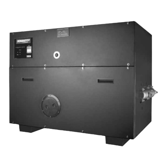
DOMINATOR SERIES FINNED COPPER
GAS BOILERS (MODEL DB) &
WATER HEATERS (MODEL DW)
INSTALLATION & OPERATION MANUAL
MEA#117-96-E
DESIGNED AND TESTED ACCORDING TO A.S.M.E. BOILER AND PRESSURE
VESSEL CODE, SECTION IV FOR A MAXIMUM ALLOWABLE WORKING PRESSURE
OF 160 PSI, 1103 kPa WATER.
WARNING: If the information in this manual is not followed exactly, a fire
or explosion may result causing property damage, personal injury or loss of life.
Do not store or use gasoline or other fl ammable vapors and liquids in the vicinity of
this or any other appliance.
WHAT TO DO IF YOU SMELL GAS:
• Do not try to light any appliance.
• Do not touch any electrical switch. Do not use any phone in your building.
• Immediately call your gas supplier from a neighbor's phone. Follow the gas
supplier's instructions.
• If you cannot reach your gas supplier, call the fi re department.
Installation and service must be performed by a qualifi ed installer, service agency or
the gas supplier.
WARNING: Failure to properly vent this unit can cause excessive amounts of carbon
monoxide resulting in severe personal injury or death!
INSTALLER, THESE INSTRUCTIONS TO BE AFFIXED ADJACENT TO THE UNIT.
CONSUMER, RETAIN THESE INSTRUCTIONS FOR FUTURE REFERENCE PURPOSES.
260 North Elm Street
7555 Tranmere Drive
Westfi eld, MA 01085
Mississauga, Ontario L5S 1L4 Canada
Phone: (413) 568-9571
Phone: (905) 670-5888
Fax: (413) 568-9613
Fax: (905) 670-5782
DOM-IOM-6
82-0262
Advertisement
Table of Contents

Related Manuals for RBI DB series


Summary of Contents for RBI DB series
- Page 1 DOM-IOM-6 82-0262 DOMINATOR SERIES FINNED COPPER GAS BOILERS (MODEL DB) & WATER HEATERS (MODEL DW) INSTALLATION & OPERATION MANUAL MEA#117-96-E DESIGNED AND TESTED ACCORDING TO A.S.M.E. BOILER AND PRESSURE VESSEL CODE, SECTION IV FOR A MAXIMUM ALLOWABLE WORKING PRESSURE OF 160 PSI, 1103 kPa WATER. WARNING: If the information in this manual is not followed exactly, a fire or explosion may result causing property damage, personal injury or loss of life.
-
Page 2: Table Of Contents
To obtain the safe, dependable, effi cient operation and long life for which this heating boiler/water heater was Direct all questions to your RBI distributor or contact the designed, these instructions must be read, understood RBI Customer Service Department, 260 North Elm and followed. -
Page 3: Ratings & Capacities
DOMINATOR INSTALLATION AND OPERATION INSTRUCTIONS Page 3 RATINGS & CAPACITIES 4. Locate the boiler/water heater in an area that will prevent water damage to adjacent construction should Before undertaking the installation of the Dominator a leak occur or during routine maintenance. If such a Series boiler/water heater check the rating plate to location doesn't exist, a suitable drain pan that's ensure that the unit has been sized properly for the job. - Page 4 Page 4 DOMINATOR INSTALLATION AND OPERATION INSTRUCTIONS CAUTION: If the boiler/water heater is operated while All Air From Inside The Building the building is under construction it MUST be If the Dominator is to be located in a confi ned space protected from wood, concrete, sheet rock and other the minimum clearances listed in Table 1 must be types of dust.
- Page 5 DOMINATOR INSTALLATION AND OPERATION INSTRUCTIONS Page 5 Figure 2 - Vertical Venting using a Masonry Chimney and Inside Air Figure 3 - Horizontal Venting using Inside Air 1/4 IN. PER F00T 20 mm/m 1.5 FT 0.5 m Table 2 MINIMUM VERTICAL RISE VENT PIPE DIAMETER OFF THE TOP OF UNIT "A"...
- Page 6 3 ft, 0.9 m intervals with overhead hangers. The Canadian installations must comply with CSA B149.1 certifi ed combustion air terminal from RBI must be used when air supply is provided by natural air fl ow from and installed as shown in Figures 4 and 5.
- Page 7 DOMINATOR INSTALLATION AND OPERATION INSTRUCTIONS Page 7 Figure 4 - Horizontal Combustion Air and Venting for a Single Unit 1/4 IN. PER FOOT 20 mm/m 16 FT 4.9 m 1.5 FT 0.5 m 2000 & Larger 1201 To 2000 901 To 1200 200 To 900 1000 BTU'S Horizontal Distance, X...
- Page 8 Page 8 DOMINATOR INSTALLATION AND OPERATION INSTRUCTIONS Figure 6 - Vertical Combustion Air and Venting, Metal Chimney System Shown Locate exhaust terminal downwind from air intake to reduce potential for fl ue gas recirculation. 10 FT 3.1 m 4 FT 1.2 m 5 1/2 FT 1.7 m...
-
Page 9: General Venting Guidelines
DOMINATOR INSTALLATION AND OPERATION INSTRUCTIONS Page 9 GENERAL VENTING GUIDELINES VENT SYSTEM OPTIONS The Dominator may be vented the following ways: WARNING: The vent installation must be in 1) Vertical/Chimney Venting, Negative Pressure, accordance with Part 7, Venting of Equipment, of the National Fuel Gas Code, ANSI Z223.1/ Category I - uses an approved metal chimney system NFPA 54-latest revision or applicable provisions... -
Page 10: Vertical/Chimney Venting
Model Size Pipe Diameter States, ULS636 for installations in Canada. The certifi ed vent terminal from RBI must also be used. 300 - 400 The maximum equivalent length for the horizontal vent and combustion air pipes is 35 ft, 10.7 m for each. Each 900 - 1050 90°... -
Page 11: Outdoor Venting
DOMINATOR INSTALLATION AND OPERATION INSTRUCTIONS Page 11 Horizontal vent systems shall terminate at least 4 ft, Horizontal vent systems shall terminate at least 4 ft, 1.2 m below, 4 ft, 1.2 m horizontally from or 1 ft, 1.2 m below, 4 ft, 1.2 m horizontally from or 1 ft, 0.3 m above any door, window or gravity air inlet into 0.3 m above any door, window or gravity air inlet into any building. -
Page 12: Common Vent Systems
Page 12 DOMINATOR INSTALLATION AND OPERATION INSTRUCTIONS Figure 8 - Outdoor Venting a) Seal any unused openings in the common venting system. Sceller toutes les ouvertures non utilisées du sys- tème d'évacuation. b) Visually inspect the venting system for proper size and horizontal pitch and determine there is no blockage or restriction, leakage, corrosion and other defi... -
Page 13: General Piping Requirements
DOMINATOR INSTALLATION AND OPERATION INSTRUCTIONS Page 13 e) Test for spillage at the draft hood relief opening after GENERAL PIPING REQUIREMENTS 5 minutes of main burner operation. Use the fl ame of a match or candle, or smoke from a cigarette, cigar CAUTION: Improper piping of this boiler/water or pipe. - Page 14 Page 14 DOMINATOR INSTALLATION AND OPERATION INSTRUCTIONS Relief Valve Table 7 - Temperature Rise Table ΔT = 15°F ΔT = 8.3°C Pipe the discharge of the pressure relief valve to prevent Model Flow Rate Pres. Drop Flow Rate Pres. Drop scalding in the event of a discharge, see Figure 10.
-
Page 15: Heating System Piping
DOMINATOR INSTALLATION AND OPERATION INSTRUCTIONS Page 15 Expansion Tank & Air Separator HEATING SYSTEM PIPING An expansion tank or other means to control thermal General Piping Requirements expansion must be installed in the heating system. An All heating system piping must be installed by a qualifi ed expansion tank must be installed close to the boiler on technician in accordance with the latest revision of the the suction side of the pump. - Page 16 Page 16 DOMINATOR INSTALLATION AND OPERATION INSTRUCTIONS Figure 11 - Typical Primary/Secondary Piping System (See Notes) Pump Gate Valve Globe Valve NOTES: Angle Valve 1. Boiler circuit piping must be sized large enough to handle maximum fl ow through unit. Bufferfly Valve 2.
- Page 17 DOMINATOR INSTALLATION AND OPERATION INSTRUCTIONS Page 17 Figure 12A - Low Temperature Piping with Thermostatic Piping (See Notes and Adjustment Procedures) Pump Gate Valve Globe Valve Angle Valve NOTES: Bufferfly Valve 1. Boiler circuit piping must be large enough to handle maximum fl ow Balance Valve through unit.
-
Page 18: Domestic Water Supply Piping
Households with small children may require water RBI water heaters are designed to run scale free. Due temperatures less than 120°F, 49°C. Local codes to the extreme variables of water conditions world wide... - Page 19 DOMINATOR INSTALLATION AND OPERATION INSTRUCTIONS Page 19 Table 8A - Dominator Heat Exchanger Selection Graph Table 8B - Dominator Pumping Performance Requirement...
- Page 20 Page 20 DOMINATOR INSTALLATION AND OPERATION INSTRUCTIONS Expansion Tank A balancing valve should be installed on the outlet side An expansion tank or other means to control thermal of the water heater for purposes of adjusting the fl ow rate expansion must be installed in the water heating system through the heat exchanger.
- Page 21 Bufferfly Valve Balance Valve D-1 Rev 6 Ball Valve Motorized Valve Attention: Not all RBI stock storage tanks incorporate this tapping: See Note 1. Solenoid Operated Valve Figure 15 - Multiple Water Heating Piping (DW Models only) Self-Operated (See Notes)
-
Page 22: Gas Supply Piping
Gas Valve Gas Cock Size, (in) heater is not for the type of gas available at the Equivalent pipe length, (ft) installation site, call your RBI representative to resolve 1ʺ the problem. ʺ ʺ NOTE: A minimum gas supply pressure of 6 in, 2ʺ... -
Page 23: Electrical Wiring
DOMINATOR INSTALLATION AND OPERATION INSTRUCTIONS Page 23 WARNING: Never use an open fl ame to test for Line voltage fi eld wiring of any controls or other devices gas leaks. Always use an approved leak must conform to the temperature limitation of type T wire detection method. -
Page 24: Boiler/Water Heater Operation
Page 24 DOMINATOR INSTALLATION AND OPERATION INSTRUCTIONS Start the boiler as described in the “OPERATING For the D1050-D2100, the air inlet plenum is divided into INSTRUCTIONS”. Run the boiler for at least an hour. left and right sides. A separate blower, main gas valve The system pump(s) and all radiation units must be and manifold are used for each side. -
Page 25: Operation Sequence, 2 Stage D300 Through D900
DOMINATOR INSTALLATION AND OPERATION INSTRUCTIONS Page 25 On the four stage units, the left low fire and high fire OPERATION SEQUENCE, 2 STAGE switches will interrupt power to the control module under D300 THROUGH D900 a blocked fl ue or inlet condition. This will cause the pilot and left and right main gas valves to close. -
Page 26: Operation Sequence, 4 Stage D1050 Through D2100
Page 26 DOMINATOR INSTALLATION AND OPERATION INSTRUCTIONS 6. If the second ignition attempt is unsuccessful the High Limit, Low Water Flow, Low Gas Pressure, gas valves will lockout, but the blower, pump and High Gas Pressure, Power Venter Interlock Faults power venter will remain on. - Page 27 DOMINATOR INSTALLATION AND OPERATION INSTRUCTIONS Page 27 Ignition Trial: NOTE: For a change from stage 2 to 3 or 3 to 4, 10 1. Once energized, the fl ame sense module (FSM) second DOM time delays were added to the initiates 4 second diagnostic cycle before sending pressure switch switching circuits (TDR2 and TDR3).
-
Page 28: Operating Instructions
Page 28 DOMINATOR INSTALLATION AND OPERATION INSTRUCTIONS OPERATING INSTRUCTIONS C. Do not use this appliance if any part has been under water. Immediately call a qualifi ed service technician FOR YOUR SAFETY READ BEFORE OPERATING to inspect the appliance and to replace any part of the control system and any gas control that has POUR VOTRE SÉCURITÉ... - Page 29 DOMINATOR INSTALLATION AND OPERATION INSTRUCTIONS Page 29 Table 19 - Pilot & Manifold Settings 11. Turn the knob on the pilot valve to on, Figure 18. 12. Turn the knob on the main gas valve to on, 300 and Natural Gas 400 models, Figure 18.
-
Page 30: Checking & Adjustments
Page 30 DOMINATOR INSTALLATION AND OPERATION INSTRUCTIONS CHECKING & ADJUSTMENTS 8. If the computed rate deviates by more than 5% from the rated input value of the unit adjust the manifold 1. With the burners in operation, close the manual pressure accordingly. -
Page 31: Control Description
DOMINATOR INSTALLATION AND OPERATION INSTRUCTIONS Page 31 Airfl ow Adjustment 4. Use a 3/32 hex wrench to turn the pressure regulator adjustment screw clockwise to increase 1. Remove the upper front jacket panel. the pilot pressure and counterclockwise to decrease 2. - Page 32 Page 32 DOMINATOR INSTALLATION AND OPERATION INSTRUCTIONS High Limit (Aquastat) Gas Pressure Switch The high limit is located in the left side area of the boiler/ An optional low and/or high gas pressure switch will shut water heater. A remote capillary bulb is run to a well on down the 24V circuit if excessively high or low gas the outlet side of the supply header.
- Page 33 DOMINATOR INSTALLATION AND OPERATION INSTRUCTIONS Page 33 Mode 3: Domestic Hot Water (DHW) generation. Mode 5: Outdoor reset control. Dominator piped in Dominator piped in parallel with the storage tank. DHW primary/secondary confi guration. An additional system demand from sensor located in tank or pool supply pipe. sensor is required to properly control the system supply The fi...
-
Page 34: Maintenance
Page 34 DOMINATOR INSTALLATION AND OPERATION INSTRUCTIONS MAINTENANCE CAUTION: Improper burner servicing can result in premature burner failure voiding the warranty! WARNING: Disconnect electrical power and Burner Inspection And Removal - Figure 20 close the manual gas shut off valve before 1. - Page 35 DOMINATOR INSTALLATION AND OPERATION INSTRUCTIONS Page 35 Heat Exchanger Removal, Cleaning & Replacement - CAUTION: Never clean the heat exchanger while it’s See Figure 20 in the boiler/water heater or the combustion 1. Close the shut off valves in the inlet and outlet chamber will be destroyed! piping.
- Page 36 Page 36 DOMINATOR INSTALLATION AND OPERATION INSTRUCTIONS Figure 21 - Heat Exchanger Upper Rail Screws 5. The aquastat high limit controls the maximum water temperature in the boiler. It should be set at least 20°F, 11°C above the operator setpoint. If the water temperature reaches the set temperature before the demand for heat has been met, the aquastat high limit should shut the boiler off.
-
Page 37: Trouble-Shooting
DOMINATOR INSTALLATION AND OPERATION INSTRUCTIONS Page 37 Trouble-Shooting PROBLEM POSSIBLE CAUSES CORRECTIVE ACTION No Power To Unit Power not connected Wire unit to line voltage External circuit breaker open Reset breaker Relay board fuse (24V) blown Replace fuse Transformer circuit breaker open Reset breaker (4 stage) No Action On Call For Heat... - Page 38 Page 38 DOMINATOR INSTALLATION AND OPERATION INSTRUCTIONS Trouble-Shooting PROBLEM POSSIBLE CAUSES CORRECTIVE ACTION Unit Does Not Spark continued Spark generator fault • Check spark generator wiring Unit Sparks But Will Not Fire Low gas pressure Check gas supply pressure, adjust as necessary Pilot valve manual knob closed Open pilot valve manual knob...
-
Page 39: Repair Parts
DOMINATOR INSTALLATION AND OPERATION INSTRUCTIONS Page 39 Figure 28 - Replacement Parts... - Page 40 Page 40 DOMINATOR INSTALLATION AND OPERATION INSTRUCTIONS SERVICE AND REPLACEMENT PARTS LIST (MODELS 300-2100) Ref # Name of Part Part # 1050 1350 1500 1950 2100 Jacket Lower Front Panel 70-2716 70-2717 70-2718 70-2719 70-2720 70-2721 70-2722 70-2723 70-2724 70-2725 Jacket Lower Front Panel (SS) 70-2716.1 70-2717.1...
- Page 41 DOMINATOR INSTALLATION AND OPERATION INSTRUCTIONS Page 41 Ref # Name of Part Part # 1050 1350 1500 1950 2100 Jacket Rear Panel 03-1811 03-1812 03-1813 03-1814 03-1815 03-1816 03-1817 03-1818 03-1819 03-1820 Jacket Rear Panel (SS) 03-1811.1 03-1812.1 03-1813.1 03-1814.1 03-1815.1 03-1816.1 03-1817.1...
- Page 42 Page 42 DOMINATOR INSTALLATION AND OPERATION INSTRUCTIONS Ref # Name of Part Part # 1050 1350 1500 1950 2100 Combustion Chamber Base Panel 03-1974 03-1975 03-1976 03-1977 03-1978 03-1979 03-1980 03-1981 03-1982 03-1983 Cerablanket Insulation 05-0103 Manning Glass Insulation (per square foot) 05-0104 Combustion Chamber Lower Front Panel 03-1962...
- Page 43 DOMINATOR INSTALLATION AND OPERATION INSTRUCTIONS Page 43 Ref # Name of Part Part # 1050 1350 1500 1950 2100 Flue Outlet Assembly 70-2736 70-2737 70-2738 70-2739 70-2740 70-2741 70-2742 70-2735 70-2743 24, 25, Tile Kit 05-0202 05-0203 05-0204 05-0205 05-0206 05-0207 05-0208 05-0209...
- Page 44 Page 44 DOMINATOR INSTALLATION AND OPERATION INSTRUCTIONS Ref # Name of Part Part # 1050 1350 1500 1950 2100 Heat Exchanger Assembly (Copper) 70-2826 Cast Iron Headers 70-2827 70-2828 70-2829 70-2830 70-2831 70-2832 70-2833 70-2834 70-2835 Heat Exchanger Assembly (Copper) 70-2846 Bronze Headers 70-2847...
- Page 45 DOMINATOR INSTALLATION AND OPERATION INSTRUCTIONS Page 45 Ref # Name of Part Part # 1050 1350 1500 1950 2100 Return Header, Bronze 01-0018S Return Header, Cast Iron 01-0023S Inlet/Outlet Header, Bronze 01-0019S Inlet/Outlet Header, Cast Iron 01-0022S Blower, Fasco 7062 12-0013 Blower, Fasco 7083 12-0014...
- Page 46 Page 46 DOMINATOR INSTALLATION AND OPERATION INSTRUCTIONS Ref # Name of Part Part # 1050 1350 1500 1950 2100 Terminal Block 2P 48-0151 Terminal Block 6P 48-0157 Terminal Block 7P 48-0153 Terminal Block 8P 48-0154 On/Off Switch 48-0010 2 Amp Fuse 48-0379 PVC Gasket Foam 66-0103...
-
Page 47: Start Up Form
Page 47 START UP FORM Date of Start Up: Job Name: Model #: Serial Number #: Boiler Model: Company Name Dominator Fuel Type: Tech Name Natural Gas Propane System Type: Phone Number Hydronic Domestic PRE-START UP CHECK LIST ANY VISUAL DAMAGE TO UNIT? INLET FILTER INSTALLED AND CLEAN? PIPING PROPERLY CONNECTED? ALL WIRING CONNECTED PROPERLY? - Page 48 Page 48 COMBUSTION/SAFETY REPORT FACTORY FIRE TEST REPORT: Low Fire High Fire These results are affi xed to the side of the heater Manifold Gas Pressure: "W.C. on a small white label. Air Differential Pressure: "W.C. FIELD TEST REPORT IN STAGE: Manifold Gas Pressure: "W.C.
-
Page 49: Installation Requirements
DOMINATOR INSTALLATION AND OPERATION INSTRUCTIONS Page 49 NOTICE! Commonwealth of Massachusetts Installation Requirements MACODE-3 In the Commonwealth of Massachusetts, the Improper venting can result in excessive levels of installation must be performed by a licensed carbon monoxide which can cause severe plumber or gas fi... - Page 50 Page 50 DOMINATOR INSTALLATION AND OPERATION INSTRUCTIONS...
- Page 51 All other RBI supplied Boiler/Water Heater parts are warranted against defects in material and workmanship for one (1) year from date of installation or 18 months from date of shipment from RBI. The “Manufacturer” warrants to the original owner at the original installation site that the heat exchanger of the Industrial, Commercial, and other Non-Residential Use Water Heater (the “Product”) will be free from defects in...
- Page 52 260 North Elm Street 7555 Tranmere Drive Westfi eld, MA 01085 Mississauga, Ontario L5S 1L4 Canada Phone: (413) 568-9571 Phone: (905) 670-5888 Fax: (413) 568-9613 Fax: (905) 670-5782...
Need help?
Do you have a question about the DB series and is the answer not in the manual?
Questions and answers