Table of Contents
Advertisement
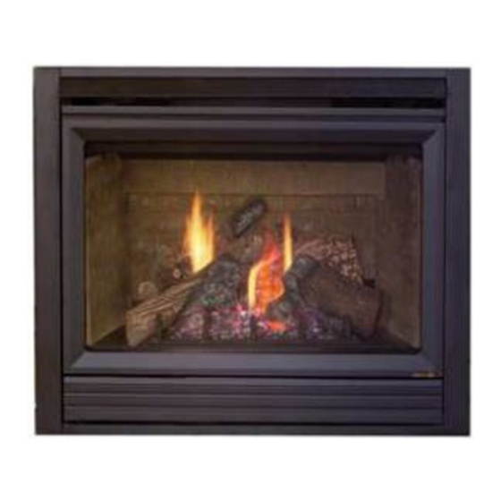
Model:
Twilight-II-B
• Important operating
a n d m a i n t e n a n c e
instructions included.
WARNING: If the information in these
instructions is not followed exactly, a fi re
or explosion may result causing property
damage, personal injury, or death.
• DO NOT store or use gasoline or other fl am-
mable vapors and liquids in the vicinity of this
or any other appliance.
• What to do if you smell gas
- DO NOT try to light any appliance.
- DO NOT touch any electrical switch. DO
NOT use any phone in your building.
- Immediately call your gas supplier from a
neighbor's phone. Follow the gas suppli-
er's instructions.
- If you cannot reach your gas supplier, call
the fi re department.
• Installation and service must be performed
by a qualifi ed installer, service agency, or the
gas supplier.
This appliance may be installed as an OEM installation in
manufactured home (USA only) or mobile home and must be
installed in accordance with the manufacturer's instructions
and the manufactured home construction and safety standard,
Title 24 CFR, Part 3280 or Standard for Installation in Mobile
Homes, CAN/CSA Z240MH, in Canada.
This appliance is only for use with the type(s) of gas indicated
on the rating plate.
NOTICE
DO NOT DISCARD THIS MANUAL
• Read, understand and follow
these instructions for safe
installation and operation.
Heat & Glo LifeStyle Collection • Twilight-II-B • 2108-900 Rev. M • 11/08
Owner's Manual
Installation and Operation
• Leave this manual with
party responsible for use
and operation.
WARNING
HOT SURFACES!
Glass and other surfaces are hot during
operation AND cool down.
Hot glass will cause burns.
• DO NOT touch glass until it is cooled
• NEVER allow children to touch glass
• Keep children away
• CAREFULLY SUPERVISE children in same room as
fi replace.
• Alert children and adults to hazards of high temperatures.
High temperatures may ignite clothing or other fl ammable
materials.
• Keep clothing, furniture, draperies and other fl ammable
materials away.
This appliance has been supplied with an integral barrier
to prevent direct contact with the fi xed glass panel. DO
NOT operate the appliance with the barrier removed.
Contact your dealer or Hearth & Home Technologies if the
barrier is not present or help is needed to properly install one.
In the Commonwealth of Massachusetts installation must be
performed by a licensed plumber or gas fi tter.
See Table of Contents for location of additional Commonwealth
of Massachusetts requirements.
Installation and service of this appliance should be
performed by qualifi ed personnel. Hearth & Home
Technologies suggests NFI certifi ed or factory trained
professionals, or technicians supervised by an NFI
certifi ed professional.
1
Advertisement
Table of Contents

Related Manuals for Heat & Glo Indoor/Outdoor Gas Fireplace Twilight-II-B

Summary of Contents for Heat & Glo Indoor/Outdoor Gas Fireplace Twilight-II-B
- Page 1 Model: Twilight-II-B • Important operating a n d m a i n t e n a n c e instructions included. WARNING: If the information in these instructions is not followed exactly, a fi re or explosion may result causing property damage, personal injury, or death.
-
Page 2: Congratulations
Read this manual before installing or operating this appliance. Please retain this owner’s manual for future reference. A. Congratulations Congratulations on selecting a Heat & Glo LifeStyle gas fi replace, an elegant and clean alternative to wood burning fi replaces. The Heat & Glo LifeStyle gas fi replace you have selected is designed to provide the utmost in safety, reliability, and effi... -
Page 3: Table Of Contents
Safety Alert Key: • DANGER! Indicates a hazardous situation which, if not avoided will result in death or serious injury. • WARNING! Indicates a hazardous situation which, if not avoided could result in death or serious injury. • CAUTION! Indicates a hazardous situation which, if not avoided, could result in minor or moderate injury. •... -
Page 4: Limited Lifetime Warranty
B. Limited Lifetime Warranty Hearth & Home Technologies LIMITED WARRANTY Hearth & Home Technologies (“HHT”) and its respective brands extends the following warranty for HHT gas, wood, pellet and electric appliances purchased from an authorized HHT dealer and installed in the United States of America or Canada. Warranty starts with date of purchase by the original owner (End User) except as noted for replacement parts. - Page 5 B. Limited Lifetime Warranty (continued) • This limited warranty does not extend to or include surface fi nish on the appliance or terminations, door gasketing, glass gasketing, glass discoloration, fi rebrick, pellet logs, kaowool or other ceramic insulating materials. Rust and/or corrosion on any of the metal surfaces, cast iron components, baffl...
-
Page 6: Listing And Code Approvals
Listing and Code Approvals A. Appliance Certifi cation MODEL: Twilight-II-B LABORATORY: Underwriters Laboratories, Inc. (UL) TYPE: Direct Vent Gas Appliance STANDARD: ANSI Z21.50-2003 • CSA2.22-M03 • UL307B This product is listed to ANSI standards for “Vented Gas Appliance Heaters” and applicable sections of “Gas Burn- ing Heating Appliances for Manufactured Homes and Recreational Vehicles”, and “Gas Fired Appliances for Use at High Altitudes”. -
Page 7: High Altitude Installations
D. High Altitude Installations NOTICE: If the heating value of the gas has been reduced, these rules do not apply. Check with your local gas utility or authorities having jurisdiction. When installing above 2000 feet elevation: • In the USA: Reduce input rate 4% for each 1000 feet above 2000 feet. -
Page 8: Requirements For The Commonwealth Of Massachusetts
Note: The following requirements reference various Massachusetts and national codes not contained in this document. H. Requirements for the Commonwealth of Massachusetts For all side wall horizontally vented gas fueled equipment installed in every dwelling, building or structure used in whole or in part for residential purposes, including those owned or operated by the Commonwealth and where the side wall exhaust vent termination is less than seven (7) -
Page 9: User Guide
Operating Instructions A. Gas Fireplace Safety WARNING HOT SURFACES! Glass and other surfaces are hot during operation AND cool down. Hot glass will cause burns. • DO NOT touch glass until it is cooled • NEVER allow children to touch glass •... -
Page 10: Fan Kit (Optional)
C. Fan Kit (optional) If desired, a fan kit may be added. Contact your dealer to order the correct fan kit. D. Clear Space WARNING! DO NOT place combustible objects in front of the fi replace or block louvers. High temperatures may start a fi... -
Page 11: For Your Safety Read Before Lighting
I. Lighting Instructions (IPI) The IPI system may be operated with two D-cell batteries. When using batteries, unplug the transformer. To prolong battery life, remove them when using the transformer. FOR YOUR SAFETY READ BEFORE LIGHTING WARNING: If you do not follow these instructions exactly, a fi re or explosion may result causing property damage, personal injury or loss of life. -
Page 12: After Fireplace Is Lit
J. After Fireplace is Lit Initial Break-in Procedure • The fi replace should be run three to four hours continu- ously on high. • Turn the fi replace off and allow it to completely cool. • Remove fi xed glass assembly. See Section 11.G. •... -
Page 13: Maintenance And Service
Maintenance and Service Any safety screen or guard removed for servicing must be replaced prior to operating the fi replace. When properly maintained, your fi replace will give you many years of trouble-free service. We recommend an- nual service by a qualifi ed service technician. A. -
Page 14: Maintenance Tasks-Qualifi Ed Service Technician
Exhaust Termination Frequency: Seasonally By: Homeowner Tools needed: Protective gloves and safety glasses. • Inspect exhaust termination for blockage or obstruction such plants, bird nests, leaves, snow, debris, etc. • Verify exhaust termination clearance to subsequent con- struction (building additions, decks, fences, or sheds). See Section 6. - Page 15 (Either cobrahead or SIT) Figure 3.2 Generic IPI Pilot Flame Pattern Heat & Glo LifeStyle Collection • Twilight-II-B • 2108-900 Rev. M • 11/08...
-
Page 16: Installer Guide
Getting Started A. Design and Installation Considerations Heat & Glo LifeStyle direct vent gas appliances are de- signed to operate with all combustion air siphoned from outside of the building and all exhaust gases expelled to the outside. No additional outside air source is required. The Twilight-II-B has been carefully engineered to pro- vide a unique fi... -
Page 17: Framing And Clearances
Framing and Clearances A. Selecting Appliance Location When selecting a location for the appliance it is important to consider the required clearances to walls (see Figure 5.1). WARNING! Risk of Fire or Burns! Provide adequate clearance around air openings and for service access. Due to high temperatures, the appliance should be locat- ed out of traffi... -
Page 18: Clearances
B. Clearances NOTICE: Install appliance on hard metal or wood surfaces extending full width and depth. DO NOT install directly on carpeting, vinyl, tile or any combustible material other than wood. WARNING! Risk of Fire! Do not install appliance against vapor barriers or exposed insulation. -
Page 19: Mantel And Wall Projections
C. Mantel and Wall Projections WARNING! Risk of Fire! Comply with all minimum clear- ances as specifi ed. Framing or fi nishing material closer than the minimums listed must be constructed entirely of noncom- bustible materials (i.e., steel studs, concrete board, etc). Combustible and Non-combustible Mantels- Indoor only NON-COMBUSTIBLE BOARD... -
Page 20: Termination Locations
Termination Locations A. Appliance Opening Minimum Clearances = 0 in ...clearances above grade, veran- (See Note 1) da, porch, deck or balcony = 12 in..clearances to window or door that may be opened, or to per- manently closed window. = 35-5/16 in. -
Page 21: Appliance Preparation
Appliance Preparation A. Removing Non-combustible Facing Ma- terial Assembly The non-combustible assembly is located on right-hand side of appliance (when looking from outdoor side of appliance). CAUTION Handle with care. • Non-combustible material may be damaged if dropped. • Hold non-combustible pieces in place. •... - Page 22 Placing and Securing Appliance Place the appliance into position. Make sure fl ashing edges on the outdoor surround fi t up tight to the framing. The diagram shows how to properly position, level, and secure the appliance (see Figure 7.2). Nailing tabs are pro- vided to secure the appliance to the framing members.
- Page 23 Apply housewrap or building paper For placement of combustible housewrap or building pa- per and non-combustible sheathing for the outside wall see Figures 7.5 and 7.6. Special care should be taken when choosing building materials for weather proofi ng (i.e. building wraps, seal- ant tapes, liquid sealants, rubberized fl...
-
Page 24: Installing Non-Combustible Facing Material (Outdoor Side)
C. Installing Non-combustible Facing Mate- rial (Outdoor Side) WARNING Fire Risk. • Follow these instructions exactly. • Facing materials must be installed properly to prevent fi re. • No materials may be substituted without authorization by Hearth & Home Technologies. •... -
Page 25: Gas Information
Gas Information A. Fuel Conversion • Make sure the appliance is compatible with available gas types. • Conversions must be made by a qualified service technician using Hearth & Home Technologies specifi ed and approved parts. B. Gas Pressure • Optimum appliance performance requires proper input pressures. -
Page 26: Electrical Information
Electrical Information A. Wiring Requirements NOTICE: This appliance must be electrically wired and grounded in accordance with local codes or, in the absence of local codes, with National Electric Code ANSI/NFPA 70-latest edition or the Canadian Electric Code CSA C22.1. •... -
Page 27: Intellifi Re Ignition System Wiring
C. Intellifi re Ignition System Wiring • Wire the appliance junction box to 110 VAC for proper operation of the appliance. WARNING! Risk of Shock or Explosion! DO NOT wire IPI controlled appliance junction box to a switched circuit. Incorrect wiring will override IPI safety lockout. •... -
Page 28: Optional Accessories
D. Optional Accessories Optional fan and remote control kits require that 110-120 VAC be wired to the factory installed junction box before the appliance is permanently installed (see Figure 9.3). Fan Installation To provide best airfl ow, we recommend positioning fan on the left side (as viewed from appliance interior side (see Figure 9.2). -
Page 29: Junction Box Installation
E. Junction Box Installation If the box is being wired from the OUTSIDE of the appliance: • Install the Romex™ connector (not included with appliance) in the side wrap. • Loosen two screws on the Romex connector, feed the necessary length of wire through the connector and tighten the screws. -
Page 30: Finishing
Finishing A. Mantel and Wall Projections WARNING! Risk of Fire! Comply with all minimum clear- ances as specifi ed. Framing closer than the minimums list- ed must be constructed entirely of noncombustible materi- als (i.e., steel studs, concrete board, etc.) Failure to comply could cause fi... - Page 31 WARNING Risk of Fire • Non-combustible clearances must be maintained. • Sheetrock, wood or other combustibles must NOT be used as sheathing or facing in the non- combustible zone. • See Sections 3 & 8 for proper clearances. • See Section 1 for combustible/non- combustible defi...
- Page 32 NOTE: All fi nishing materials on top of exterior sheathing must be non-combustible for a minimum of 12 inches above and on both sides of the exterior face of the appliance. This non-combustible fi nishing material can be up to a maximum of 6 inches thick (6 inches maximum horizontal overhang) to allow for brick and stone alcoves (see Figure 8.5).
-
Page 33: Appliance Setup
11 11 Appliance Setup A. Remove Fixed Glass Assembly See Section 11.G. B. Remove the Shipping Materials Remove shipping materials from inside or underneath the fi rebox. C. Clean the Appliance Clean/vacuum any sawdust that may have accumulated inside the fi rebox or underneath in the control cavity. D. -
Page 34: Install The Log Assembly
F. Install the Log Assembly CAUTION: Logs are fragile! Carefully remove the logs from the packaging. Remove the cardboard support from inside of fi replace. INDENT INDENT BOTTOM VIEW BOTTOM VIEW INDENT INDENT BACK VIEW BACK VIEW STEP 2. LOG #1 (SRV2005-701): Use the indent on the bottom side of the log to position the large end of the log onto the grate bar as shown. - Page 35 STEP 4. LOG #3 (SRV2005-702): Position log #3 as shown by leaning it against log # 2 and resting the other end on the peak of the burner. DO NOT cover any port holes. SHARP SHARP NOTCH NOTCH STEP 5. LOG #4 (SRV2005-703): Locate the sharp notch on log #4 against the grate tine as shown.
- Page 36 STEP 7. LOG #6 (SRV2005-705): Locate the notch on log #6 and place it against the front right grate tine. Set the other end of the log so it rests on the fl at area of log #1. The orientation of log #6 in relation to the grate tine is shown below.
-
Page 37: Fixed Glass Assembly
G. Fixed Glass Assembly WARNING! Risk of Asphyxiation! Handle fi xed glass assembly with care. Inspect the gasket to ensure it is undamaged and inspect the glass for cracks, chips or scratches. • DO NOT strike, slam or scratch glass. •... -
Page 38: Troubleshooting
Troubleshooting With proper installation, operation, and maintenance your gas appliance will provide years of trouble-free service. If you do experience a problem, this troubleshooting guide will assist a qualifi ed service technician in the diagnosis of a problem and the corrective action to be taken. This troubleshooting guide can only be used by a qualifi ed service technician. Contact your dealer to arrange a service call by a qualifi... - Page 39 Intellifi re Ignition System - (continued) Symptom A. A shorted or loose connection in fl ame 4. Pilot lights but contin- sensing rod. ues to spark, and main burner will not ignite. (If the pilot continues to spark after the B.
-
Page 40: Reference Materials
Reference Materials A. Appliance Dimension Diagram Dimensions are actual appliance dimensions. Use for reference only. For framing dimensions and clearances refer to Section 5. OUTDOOR GAS LINE ACCESS INDOOR VIEW Location Figure 13.1 Appliance Dimensions Heat & Glo LifeStyle Collection • Twilight-II-B • 2108-900 Rev. M • 11/08 OUTDOOR Inches Millimeter... -
Page 41: Service Parts
Twilight-II-B B. Service Parts Beginning Manufacturing Date: Jan. 2006 Service Parts Diagram Ending Manufacturing Date: ______ Log Set Assembly Wind Screen Assembly 2086-004MBK 2086-022 Part number list on following page. Heat & Glo LifeStyle Collection • Twilight-II-B • 2108-900 Rev. M • 11/08... - Page 42 Service Parts IMPORTANT: THIS IS DATED INFORMATION. When requesting service or replacement parts for your appliance please provide model number and serial number. All parts listed in this manual may be ordered from an authorized dealer. ITEM DESCRIPTION Log Set Assembly /Burner Assembly Log Set Assembly Log 1 Log 2...
- Page 43 IPI Valve Assembly IMPORTANT: THIS IS DATED INFORMATION. When requesting service or replacement parts for your appliance please provide model number and serial number. All parts listed in this manual may be ordered from an authorized dealer. ITEM DESCRIPTION Burner Orifi ce (NG) (#32C) Burner Orifi...
-
Page 44: Contact Information
C. Contact Information Heat & Glo LifeStyle , a brand of Hearth & Home Technologies Inc. Please contact your Heat & Glo LifeStyle dealer with any questions or concerns. For the location of your nearest Heat & Glo LifeStyle dealer, ________________________________________________________________________________ ________________________________________________________________________________ ________________________________________________________________________________...
Need help?
Do you have a question about the Indoor/Outdoor Gas Fireplace Twilight-II-B and is the answer not in the manual?
Questions and answers