
Related Manuals for Hayter Powertrim 407D

Summary of Contents for Hayter Powertrim 407D
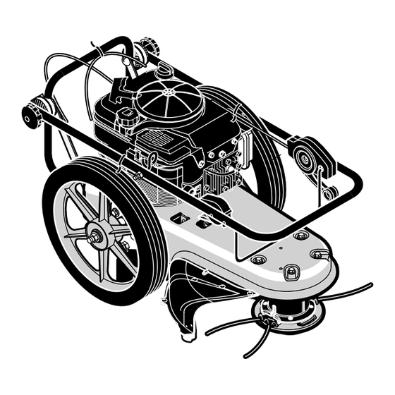
- Page 1 POWERTRIM Code 407D OWNER’S HANDBOOK FROM SERIAL NO:407D001001 PART NO: 111-0443 (rev.0.) ISSUE: 01-20-06...
-
Page 2: Table Of Contents
OWNER’S INFORMATION SAFETY PRECAUTIONS INTERNATIONAL PICTORIALS ASSEMBLY OPERATION MAINTENANCE TROUBLE SHOOTING CHART REPAIR PARTS Declared vibration emission values in accordance with Directive 98/37/EC. Vibration Emission according to EN 836/A2:2001: 10 m/s Values determined at the handle when the machine was operated stationary on a concrete surface at 3600 min-1. -
Page 3: Limited Warranty
Hayter Limited warrants to the original user / purchaser that this unit shall be free from defects in material and workmanship under normal use and service for a period of three years from the date of purchase. The manufacturers of the engine and battery pack system (where applicable) furnish their own warranty and services are provided through their authorised network (Refer to “Engine/Battery Pack Warranty Statement”). -
Page 4: Safety Rules
OWNER’S INFORMATION Know your product: If you understand the unit and how the unit operates, you will get the best performance. As you read this manu- al, compare the illustrations to the unit. Learn the location and the function of the controls. To help prevent an accident, follow the oper- ating instructions and the safety rules. - Page 5 Verify that the control bail is working properly. 19. Stop the rotating trimmer head when crossing gravel drives, walks, or roads. Wait for the cutting lines to stop rotating. 20. Watch for traffic when operating near, or when crossing roads.
- Page 6 Keep all nuts and bolts tight and keep equipment in good condition. Check mounting hardware on trimmer head ev- ery time you change trimmer line and prior to each use. Never tamper with safety devices. Check their proper operation regularly.
-
Page 7: International Pictorials
INTERNATIONAL PICTORIALS IMPORTANT: The following pictorials are located on your unit or on literature supplied with the product. Before you operate the unit, learn and understand the purpose for each pictorial. Safety Warning Pictorials WARNING IMPORTANT: Read Owner’s Manual Before Operating This Machine. WARNING: Thrown Objects. -
Page 8: Assembly
2. Remove the packing material positioned 3. Cut down all four corners of the carton and 4. Pull the trimmer out of the carton and off 5. Remove packing material from around the 6. Remove protective plastic from front of 2 Sets −... - Page 9 HOW TO ATTACH THE GUARD 1. Attach the guard to the machine with the four fasteners as shown. See Figure 3. Guard 276798MA DRAFT COPY ASSEMBLY Handle Rope Guide Recoil Start Handle Handle Pivot Handle Adjustment Knob Figure 2 Trimmer Fastener Figure 3...
-
Page 10: Engine Preparation
ENGINE PREPARATION Note: Engine does not contain OIL or PETROL. WARNING: Follow the engine manufacturer’s instructions for the type of petrol and oil to use. Always use a safety petrol container. Do not smoke when adding petrol to the en- gine. -
Page 11: Operation
Throttle Control Lever Recoil Starter Handle Handle Adjustment Knob Fuel Cap Trimmer Head Drive Lever − the rotation of the trimmer head. Control Bail − Release to stop the rotation of the trimmer head. EYE PROTECTION WARNING: Debris thrown from... -
Page 12: How To Use The Throttle Control
HOW TO USE THE TRIMMER HEAD DRIVE LEVER 1. To engage the trimmer head, hold the con- trol bail against the handle. Move the trimmer head drive lever forward to en- gage the trimmer head. See Figure 6. The faster the engine runs, the faster the trim- mer head will rotate. -
Page 13: How To Start The Engine
This is easily done by moving slowly through very thick or heavy weeds. If the trimmer lines become too short, it will 276798MA DRAFT COPY OPERATION NOTE: If engine fails to start after three pulls, push the primer button two times and again pull the recoil starter handle. -
Page 14: Maintenance
CUSTOMER RESPONSIBILITIES SERVICE RECORDS Fill in dates as you complete regular service. Check Engine Oil Level Check trimmer Lines Check Trimmer Head Engagement Engine/Machine Cleaning Check Nuts and Bolts Check Spark Plug Change Engine Oil Service Air Filter Lubricate Jackshaft Assembly Lubricate Wheel Bearings Note 1 −... - Page 15 LUBRICATION How To Lubricate The Jackshaft Assembly A grease fitting is provided to lubricate the jackshaft assembly. Use a grease gun with au- tomotive type grease to lubricate the jackshaft assembly as shown in Figure 10. How To Change Engine Oil Change the engine oil when the engine is warm.
-
Page 16: Spark Plug
SPARK PLUG Check the spark plug every 25 hours. Re- place the spark plug if the electrodes are pitted or burned or if the porcelain is cracked. Make sure the spark plug is clean. Clean the spark plug by carefully scraping the electrodes (do not sand blast or use a wire brush). -
Page 17: Service And Adjustment
This is important to make sure the trimmer head is balanced and does not vibrate. HOW TO CHANGE TRIMMER LINES When the trimmer line becomes worn to half the original length, replace the trimmer line as follows: Line Trimmer... - Page 18 HOW TO REPLACE THE DRIVE BELT To replace the drive belt, the trimmer head and shield must be removed as follows. WARNING: Before you remove the drive belt, disconnect the wire from the spark plug. 1. Remove the two fasteners that hold the rear of the shield to the trimmer housing (See Figure 14).
- Page 19 When the machine is put in storage for thirty days or more, follow the steps below to make sure the machine is in good condition the following season. Trimmer Completely clean the machine. Put the machine in a building that has good ventilation.
-
Page 20: Trouble Shooting Chart
TROUBLE SHOOTING CHART TROUBLE Engine does not start Engine runs poorly. 276798MA DRAFT COPY CAUSE Spark plug wire disconnected. Engine not primed. Defective or incorrectly gapped spark plug. Fuel tank empty. Dirty carburetor or fuel line. Dirty air filter. Carburetor out of adjustment. Engine flooded. - Page 21 Carburetor out of adjustment. Oil level is low. Defective throttle control lever or wire. Throttle not adjusted properly. Trimmer line length is too short. Engine not set at FAST speed. Trimmer line lengths are substantially different. Loose nuts or bolts.
-
Page 22: Repair Parts
Code 407D 276798MA DRAFT COPY 6 20 REPAIR PARTS... - Page 23 −− −− −− −− 276798MA DRAFT COPY Part No. Description MU740198E549 Lever, Stop MU323035 Bolt MU740193 Cable, Control Latching MU071372 Tie, Cable MU740196E701 Handlebar MU15x116 MU1601039 Control, Throttle MU672510 Guide, Rope MU740202 Knob, Handlebar MU783000 Washer MU711936 Washer, Spring MU711937 Bolt MU672292 Spacer...
- Page 24 Code 407D 276798MA DRAFT COPY REPAIR PARTS...
- Page 25 276798MA DRAFT COPY Part No. Description MU015x84 MU025x11 Screw MU740150E549 Frame, Trimmer MU26x256 Screw MU740231 Z Bracket, Idler Assembly MU009x48 Bolt MU712403 Spring MU740292 Spacer MU15x119 MU17x104 Washer MU740171 Pulley, Cutting Head MU740173 Spacer MU711933 Belt MU740244 Pulley, Idler MU740179...
- Page 26 NOTES 276798MA DRAFT COPY...
- Page 27 NOTES 276798MA DRAFT COPY...
- Page 28 How To Order Replacement Parts Use only manufacturer’s authorised or approved replacement parts. The letter placed on the end of the part number denotes the type of finish for the part, C for chrome, Z for zinc, a PA for purchased assembly. It is important that you include this when ordering a part.
Need help?
Do you have a question about the Powertrim 407D and is the answer not in the manual?
Questions and answers