Advertisement
Advertisement
Table of Contents

Subscribe to Our Youtube Channel
Related Manuals for Peavey VSX 26


Summary of Contents for Peavey VSX 26
- Page 1 ™ Digital Loudspeaker Processor Operating Manual www.peavey.com...
- Page 2 ATTENTION: Afin de réduire le risque de choc électrique, ne pas enlever le couvercle. Il ne se trouve à l’intérieur aucune pièce pouvant être reparée par l’utilisateur. Confiez I’entretien et la réparation de l’appareil à un réparateur Peavey agréé. AVIS: Dans le but de reduire les risques d’incendie ou de decharge electrique, cet appareil ne doit pas etre expose a la pluie ou a l’humidite et aucun objet rempli de liquide, tel qu’un vase, ne doit...
-
Page 3: Important Safety Instructions
IMPORTANT SAFETY INSTRUCTIONS WARNING: When using electrical products, basic cautions should always be followed, including the following: Read these instructions. Keep these instructions. Heed all warnings. Follow all instructions. Do not use this apparatus near water. Clean only with a dry cloth. Do not block any of the ventilation openings. - Page 4 ™ Digital Loudspeaker Processor The VSX 26 is a fully progammable 32-bit audio processing and louspeaker management control system. Considerably more powerful than similarly priced units, the VSX 26 provides a versatile and economical alternative for system designers. Please read this guide carefully to ensure your personal safety as well as the safety of your equipment.
-
Page 5: Front Panel
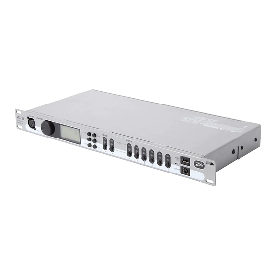
Front Panel Input Section (1) RTA MIC INPUT Mic level input for measuring mic. Phantom power may be selected in software. May be used as a extra input and routed through the system. (2) DATA WHEEL Rotate clockwise or counter clockwise to scroll through screens. Push to enter or confirm selection. (3) LCD DISPLAY This screen gives a graphical representation of unit configuration and parameter settings. -
Page 6: Rear Panel
Rear Panel (1) IEC POWER INPUT and FUSE HOLDER (2) OUTPUTS XLR male line level outputs (3) INPUTS XLR female line level inputs. Input A may be switched to AES digital input via software. - Page 7 Setup/Configuration Screen Rotate the data wheel to scroll across the screen and push the wheel to select and confirm. A & B INPUTS: Input sensitivity switchs between –10 dBV or +4 dBV inputs. The +4 dB position should be considered the “normal” position and should be used with professional systems.
-
Page 8: Bandwidth Select
Setup/Configuration Screen SETUP: Selecting this button takes you to the preset configuration page. The VSX™ is pre-programmed with eight configuration templates representing the most frequently used crossover possibilities. As you scroll through the configuration presets you will see and can adjust the basic filter types (only symmetrical choices may be made here). - Page 9 EQ Screen OUTPUT EQUALIzERS Select 1-6 on the top of the EQ screen. FILTER: Select any of the five independent filters to use. TYPE: Choices are: Parametric, Notch, Allpass1, Allpass2, Horn EQ, LPF-6, LPF-12, HPF-6, HPF-12, Low Shelf, High Shelf and Bandpass.
- Page 10 EQ Screen RELEASE: The Release value sets the amount of time for the compressor to recover from the compressed state once the level falls below the threshold level. We recommend release times of 5x to 10x the Attack time in normal use. GAIN: This adjustment serves to compensate for the loss in average signal strength due to compression.
-
Page 11: Delay Screen
Delay Screen Inputs A and B or outputs 1-6 should be selected on the top of the screen. While on the top of the screen push the data wheel and an arrow appears. Rotate the wheel to select which input or output you wish to adjust. -
Page 12: Save Preset
Tools SAvE PRESET Allows saving the current configuration to one of 8 internal memory positions or to an external USB memory stick. If external USB is selected the VSX™ will automatically write a folder and file to the stick without disturbing other files/folders that may be present on the stick. -
Page 13: Block Diagram
™ BLOCk DIAGRAm 5 PEQ COMP 27 GEQ COMP 5 PEQ COMP ST /M 27 GEQ COMP 5 PEQ COMP 5 PEQ COMP RTA INPUT 5 PEQ COMP GENERAT OR 5 PEQ COMP... -
Page 14: Specifications
™ SPECIFICATIONS Comments Audio Channels 3 inputs/6 outputs RTA Mic input can be summed with Line inputs. LED metering 2 inputs/6 outputs LED STATUS: Red = -0.5 dBFS and higher (Clip) Red & Green = -4 to -0.5 dBFS Green = -4 to -40 dBFS Off = below -40 dBFS mute Function Front panel switch and LED for each input and... - Page 15 ™ SPECIFICATIONS Comments DIGITAL Sample Rate 48 kHz QUANTIZATION 24-bit 256 x-over- sampled Delta-Sigma AD, DA Digital Processing ~100 32-bit MIP Uses Analog Devices BLACKFIN processors, 40-bit accumulators DSP Cycle Speed 500 MHZ CONTROL/mEmORY 2.0 PC, Memory Stick, PDA Connection GENERAL Dimensions 19"...
- Page 16 Features and specifications subject to change without notice. Peavey Electronics Corporation • 5022 Hartley Peavey Drive • Meridian, MS • 39305 (601) 483-5365 • FAX (601) 486-1278 • www.peavey.com EX 000047 ©2006...
Need help?
Do you have a question about the VSX 26 and is the answer not in the manual?
Questions and answers