Table of Contents
Advertisement
Advertisement
Table of Contents

Related Manuals for Sony MKS-8080


Summary of Contents for Sony MKS-8080
- Page 1 AUX BUS REMOTE PANEL MKS-8080/8082 OPERATION MANUAL [English] 1st Edition...
- Page 2 Using this unit at a voltage other than 120V may require the WARNING use of a different line cord or attachment plug, or both. To To prevent fire or shock hazard, do not expose the unit to rain reduce the risk of fire or electric shock, refer servicing to or moisture.
- Page 3 WARNING This unit has no power switch. When installing the unit, incorporate a readily accessible disconnect device in the fixed wiring, or connect the power cord to socket-outlet which must be provided near the unit and easily accessible. If a fault should occur during operation of the unit, operate the disconnect device to switch the power supply off, or disconnect the power cord.
-
Page 4: Table Of Contents
Functions of the Parts on the Front Panel........9 Functions of the Parts on the Rear Panel ......... 11 Preparations ............... 12 Settings on the Control Terminal..........12 Preparations for the MKS-8080/8082........12 Making the Settings With Buttons (Setup Function)....15 Operations ................16 Signal Selection ............... 16 Assignment (Setting the Name for a Source Select Button)..16... -
Page 5: Overview
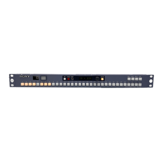
The preset display window indicates the current status and entry/preset information. The operation mode can be set The MKS-8080 occupies 1 unit in height in a standard 19- separately from a connected computer with the terminal inch rack, and has 32 source select buttons and four reentry software installed (hereinafter called the terminal). -
Page 6: System Connection Example
(for setup) RS-232C KEY X-HOLD DEST ASSIGN M/E 1 M/E 2 M/E 3 P/P (D-sub 9-pin) AUX BUS REMOTE PANEL MKS-8080 MKS-8080 AUX Bus Remote Panel PFV-D10 + BKPF-R70A S-BUS primary station AUX BUS REMOTE PANEL MKS-8082 SELECTOR... -
Page 7: Location And Function Of Parts
KEY X-HOLD DEST ASSIGN M/E 1 M/E 2 M/E 3 P/P AUX BUS REMOTE PANEL MKS-8080 iSource select buttons Rear panel REMOTE 1 RS-232C REMOTE 2 -AC IN eREMOTE 2 connector... -
Page 8: Mks-8082 Parts
MKS-8082 Parts Front panel 5 Preset display window 6 SELECTOR knob AUX BUS REMOTE PANEL MKS-8082 7 ASGN button 4 DEST button SELECTOR qs LEVEL button ASGN DEST LEVEL qd RTR button 10 11 12 13 14 15 16 qf CLEAR button LOCK CLEAR HOLD... -
Page 9: Functions Of The Parts On The Front Panel
If you press this button, the ID of corresponding signals. The abbreviation of a description is the station will be displayed. obtained according to the format of Sony-made production switchers, which uses the first two and last two characters To release the crosspoint hold/protect setting of a description. - Page 10 • The selectable range is limited according to the available using the level table of the primary station.) source/destination table. j Destination select buttons (MKS-8082 only) g ASSIGN button (MKS-8080), ASGN (assign) Select the destination assigned to a button. button (MKS-8082) k Source display windows (MKS-8082 only)
-
Page 11: Functions Of The Parts On The Rear Panel
If you press the button while it is lit in red, the button goes Functions of the Parts on the Rear dark, and the lock is released. Panel CHOP function When you hold the button pressed for about 3 seconds, the a -AC IN (AC power input) connector button lights in green, and the chop mode is obtained. -
Page 12: Preparations
Setup the global phantom, etc. as required. The ID number will appear in the Preset display window in the format ID = xxx. Preparations for the MKS-8080/8082 Press the ASSIGN/ASGN button. The set station number is registered. You may use up to 253 control units, including this unit, in... - Page 13 Put the key cap, key label with the name written on it, and diffuser on the button and reinstall the cap. To obtain a key-cap puller (part number: 3-179-054-01), consult your Sony representative. Preparations...
- Page 14 Key label guide For a large button (13 13 mm) 13 mm For a small button (9.5 9.5 mm) 9.5 mm Preparations...
-
Page 15: Making The Settings With Buttons (Setup Function)
Numbers of the source-select buttons While holding down buttons [4] and [5], turn the power on. To return to the factory-set button numbers, perform the same operation. MKS-8080 List of setup operations Settings Buttons to be pressed MKS-8082... -
Page 16: Operations
Breakaway (MKS-8082 Only) Operations Different sources can be used with multiple levels. Selecting Breakaway Signal Selection First select the destination, then the source. The level Press the LEVEL button. selection depends on the setting at the terminal. Before starting operations, turn on this unit and other Using source select buttons [1] to [8], select the desired system equipment, and check that the X-HOLD/XPT breakaway levels. -
Page 17: Menu Operations
(5) A simultaneous press of two keys is indicated by connecting the names of keys with a hyphen (ex. [Ctrl]- Selection display of the Setup Menu [X]). SONY ROUTING SYSTEM SETUP MENU MKS-8082 V1.00 STATION NUMBER 6 MODIFICATION COMMAND Key functions in settings... -
Page 18: Display And Entry Method For Names
The setting display of menu item C appears. In DESCRIP.NAME (description name) Setting display (example) mode SONY ROUTING SYSTEM SETUP MENU MKS-8082 V1.00 STATION NUMBER 6 • The name of a source or destination is displayed with a SET SWITCHER ID description name. -
Page 19: Menu Item D: Set Aux Destination/Source (For Aux Mode)
The setting display of menu item D appears. The entered name is registered. To set SET SOURCE TABLE Setting display (example) Press [F1]. SONY ROUTING SYSTEM SETUP MENU MKS-8082 V1.00 STATION NUMBER 6 SET AUX DESTINATION CONTROL DESTINATION = OUT001... -
Page 20: Menu Item H: Set Phantom Table (For Router Mode)
To return to the selection display of the Setup Menu Item H: SET PHANTOM TABLE Menu (for Router mode) Pressing [Ctrl]-[E] on each setting display. To return to the primary station menu Press [Ctrl]-[D]. Purposes Menu item H enables you to specify a phantom function to TAKE function and SHIFT function switch multiple crosspoints at a time using a source select button in RTR mode on the remote control unit. - Page 21 Setting display (example) or the Type + Number name. Each time you press [Ctrl]-[N], Description Input mode SONY ROUTING SYSTEM SETUP MENU MKS-8082 V1.00 STATION NUMBER 6 and Type + Num Input mode are toggled.
- Page 22 Executing a phantom Processing when the TAKE button is pressed When a phantom is executed from a remote control panel, operation is performed according to the phantom table set When you select a source then press the button on which on this menu.
-
Page 23: Menu Item N: Set Panel Table (For Router Mode)
The setting display of menu item N appears. signals for example) is to be set. Setting display (example) Setting of Destination Offset Phantom IN001: DST+000<IN001-10000000 SONY ROUTING SYSTEM SETUP MENU MKS-8082 V1.00 STATION NUMBER 6 IN001: DST+001<IN002-10000000 SET PANEL TABLE (SOURCE) CONTROL DESTINATION = OUT017... - Page 24 Settings for select buttons (assigning Notes sources/destinations to be selected) • Set the destination to be used as default when the power is turned on in CONTROL DESTINATION. To use this For a button to be used as a select button, assign a source unit as a single-destination panel, enter the name of the and/or a destination to be selected when you press the destination to be used here.
-
Page 25: Menu Item R: Set Route
Notes Menu Item R: SET ROUTE • The button for which the TAKE function has been set cannot be used as a source select button. Purposes • The TAKE button set in Menu item N will be enabled in AUX mode as well. Menu item R enables you to set the routing function. - Page 26 Setting display (example) route is in effect when you use the same route for multiple destinations (there are multiple units as switcher B) from a SONY ROUTING SYSTEM SETUP MENU MKS-8082 V1.00 STATION NUMBER 6 SET ROUTE (ROUTE DESTINATION : DESTINATION < SOURCE-LEVEL) single panel.
-
Page 27: Menu Item O: Set Available Destination
The setting display of menu item O appears. Setting for selectable sources (example) Setting for the selectable destinations display (example) SONY ROUTING SYSTEM SETUP MENU MKS-8082 V1.00 STATION NUMBER 6 SELECT SOURCE NAME SRC TOP - SRC END = DST TOP - DST END SONY ROUTING SYSTEM SETUP MENU MKS-8082 V1.00... - Page 28 Block 3 Setting display and virtual matrix (example) SONY ROUTING SYSTEM SETUP MENU MKS-8082 V1.00 STATION NUMBER 6 SELECT SOURCE NAME SRC TOP - SRC END =DST TOP - DST END...
-
Page 29: Menu Item L: Copy Table Data From
Setting procedure cursor is placed at “DISPLAY MODES = 1.” Press [L] on the selection display to select menu item Setting display (example) SONY ROUTING SYSTEM SETUP MENU MKS-8082 V1.00 STATION NUMBER 6 The display of menu item L appears. -
Page 30: Menu Item Z: Set Panel Status
The setting display of menu item Z appears. PANEL FUNCTION Setting display (example) Specify the operation mode of the panel. SONY ROUTING SYSTEM SETUP MENU MKS-8082 V1.00 STATION NUMBER 6 NORMAL: Normal selection mode. SET PANEL STATUS 4 DESTINATION: You can specify destinations for each... - Page 31 DISPLAY MODE PHANTOM PROTECT (MKS-8082 only) Set the mode for the panel display. Specify one of these operation modes for phantom Normally use STATUS mode. switching when there is a protected destination. Normally use PART PROT mode. 1: STATUS Checking the latest crosspoint information, the unit turns 1: PART PROT on the button that corresponds to the currently selected Only unprotected signals are switched.
- Page 32 DEST SELECTION SOURCE OFFSET (MKS-8082 only) Enable/disable destination change from the unit. When the monitor function is on, monitoring is possible while adding an offset specified in this item for the number 1: DISABLE of the source to be monitored. Destination changing is disabled.
-
Page 33: Menu Item S: Display Description Name
DESCRIP.NAME, and shows the description name list. Calling the Menu item S display Press [S] on the selection display to select menu item S. Source list (example) SONY ROUTING SYSTEM SETUP MENU MKS-8082 V1.00 STATION NUMBER 6 SOURCE name... -
Page 34: Error Messages
Error Messages When trouble occurs with this unit, the following error messages appear in the display window. The displayed message will automatically disappear after a few seconds. Pressing the CLEAR button also makes the displayed message disappear on the MKS-8082. Error messages Contents Remarks... -
Page 35: Specifications
MKS-8080: 440 116.5 mm inches) MKS-8082: 440 120 mm inches) Mass MKS-8080: Approx. 1.4 kg (3 lb) MKS-8082: Approx. 2.6 kg (5 lb 12 oz) Accessories supplied Operation Guide (1) T bridge (1) Design and specifications are subject to change without notice. - Page 36 Specifications...
- Page 37 The material contained in this manual consists of information that is the property of Sony Corporation and is intended solely for use by the purchasers of the equipment described in this manual. Sony Corporation expressly prohibits the duplication of any...
- Page 38 Sony Corporation B & P Company MKS-8080/8082(SY) © 2001 3-206-522-01 (1)