Table of Contents
Advertisement
Quick Links
Advertisement
Chapters
Table of Contents

Related Manuals for Nexus Multi Control


Summary of Contents for Nexus Multi Control
- Page 1 - Instrument and Server - Installation and Operation Manual...
- Page 2 Navigation terms BOD: Bearing origin destination BTW: Bearing to Waypoint CMG: Course made good COG. Course over ground CTS: Course to steer DMG: Distance made good DRF: Drift speed DTW Distance to Waypoint Magnetic North North SET: Drift direction SOG: Speed over ground XTE: Cross track error...
- Page 3 This manual is written for Nexus Multi Control and Server instrument version 2.00 Edition: June 2000...
-
Page 4: Table Of Contents
CONTENTS 1 Part specification ....................7 2 Installation - Contents.................... 9 2.1 Location of the Server ..................11 2.2 Installing the Server ..................11 2.3 Location of the instrument ................12 2.4 Installing the instrument ................. 12 2.5 Installing the transducers ................14 2.6 Connecting optional accessories .............. - Page 5 13.1 Maintenance ....................70 13.2 Fault finding ....................70 14 Specifications..................... 74 14.1 Technical specifications ................74 14.2 Nexus databus introduction and user policy ..........74 14.3 Optional Accessories..................75 14.4 Abbreviations ....................77 14.5 Warranty...................... 80 For more detailed contents specifications, see beginning of each new chapter...
-
Page 6: Part Specification
Connection back cover 4-pole jack plug Silicon paste tube Plastic cable strap Adhesive drill template for instrument Nexus Network cable, 8 m (26 ft) Quick guide laminated Inter-connection cable, 0,3 m (1 ft ) Installation and Operating manual Warranty card... - Page 7 PART SPECIFICATION...
-
Page 8: Pole Jack Plug
INTRODUCTION Welcome aboard the Nexus Network! Thank you for choosing Nexus and welcome to the world of the Nexus Network. Through this manual we would like to help you install, operate and understand your new Nexus Network. The Server is the ”heart” of your Nexus Network, to which transducers for speed, depth, heading, wind and navigation (GPS, Loran or Decca) are connected. - Page 9 INTRODUCTION Again, thank you for choosing Nexus. If you see us at a show, stop by and say hello. Good luck and happy boating!
-
Page 10: Installation - Contents
2.6.1 Man over board (MOB) push-button ............14 2.6.2 Tactical function push-button............... 15 2.6.3 Extra alarm buzzer ..................15 2.6.4 Nexus instruments ..................15 2.6.5 Maxi repeater ....................16 2.7 Connecting instrument lighting................16 2.8 Connecting a NMEA instrument IN to the Server..........16 2.9 Connecting a NMEA instrument OUT from Server.......... - Page 11 2.8 mm (0.11") drill for the mounting holes Plastic cable ties If the cable is not long enough, you can buy the optional Nexus 8 m (26 ft) extension cable ( Art. No.21266-8 ), or use left over Nexus cable from other installations. The same 4-pole Nexus cable is used for all connections.
-
Page 12: Location Of The Server
Drill the 4 screw holes using a 2.8 mm (0.11") drill. Mount the Server using the 4 mounting screws. Apply silicon paste on the screw terminal. Connect the 8 m Nexus Network cable labelled number 5 and supplied with cable protectors to the Server on pins 5, 6, 7, and 8. -
Page 13: Location Of The Instrument
Run the Nexus Network cable from the Server to the instrument. Cut the Nexus Network cable to length. Peel off about 35 mm (1,4") of the cable insulation. Remove about 6 mm (1/4") from the 3 isolated wires (the 4:th wire is a earth / screen). Attach the 4 cable protectors to the wires using a pair of flat pliers. -
Page 14: Connection Back Cover
INSTALLATION Silicon paste Silicon paste Apply silicon paste to the instrument connection pins at the back of the instrument. Press the jack plug onto the instrument pins. Press down the cable in the cable leads. Mount the connection back cover with the 1 screw. Mount the instrument in the pre-drilled position. -
Page 15: Installing The Transducers
Install the transducers according to the separate instructions supplied with each transducer. Connect as per below drawings Connecting optional accessories These optional accessories are available from your local Nexus Dealer. (For a more complete list of accessories available, see 14.4). 2.6.1 Man over board (MOB) push-button Art. -
Page 16: Tactical Function Push-Button
Red wire to Server pin 2 (ALARM RED). Black wire to Server pin 4 (BLACK). 2.6.4 Nexus instruments All Nexus instruments are connected directly to the Nexus Network in a daisy chain. They all use the same colour coded 4-pole jack plugs. (For instrument installation, see 2.2). -
Page 17: Connecting Instrument Lighting
GPS, Decca, Loran, NMEA compass and wind transducer etc. If a NMEA instrument is connected, most information will be available and can be displayed on the Nexus Network. You must know which 2 cables from your other NMEA instrument carry the NMEA out signal. If you have trouble call the dealer you bought your NMEA instrument from. -
Page 18: Connecting A Nmea Instrument Out From Server
Note b: We do not recommend the use of NMEA transducers like wind and compass, because the update rate of data is slow compared to the very fast Nexus data bus. Note c: If the NMEA instrument has only one output cable, put a ”bridge”... -
Page 19: Compatibility With Our Previous Transducers
INSTALLATION Note a: Try to keep the power cables as short as possible. Note b: Up to 32 Nexus instrument units (Server, digital and analogue instruments, Autopilot servo-unit or a Nexus GPS) can be connected to the single Nexus data bus cable. -
Page 20: Depth Transducer
INSTALLATION 2.11.2 Depth transducer Our depth transducers with stand alone amplifier boxes can be used, that is the Direction D30 and Power depth. Note: Do not mix amplifier boxes with transducers from other series. Direction Power 2.11.3 Wind transducer All our wind transducers can be used. POWER S-400 S-4000... -
Page 21: Compass Transducer
Compass transducer for S-5000, D50, S-520/S-525 and POWER can be upgraded to Nexus standard. Contact your local Nexus dealer for a quote. 2.11.5 GPS receiver All Nexus GPS products can be connected directly to the Nexus Network. 2.11.6 NMEA transducers NMEA compass and NMEA wind transducer. -
Page 22: First Star - Contents
The Server automatically gives the first unit ID number 16, then 17 and so on. The order in which you press KEY is the same order as the instruments will be given a logical ID number on the Nexus Network. -
Page 23: Operation - Contents
OPERATION CONTENTS OPERATION 4.1 About this manual ....................23 4.2 How to use the 4 push-buttons ................24 4.2.1 MODE......................24 4.2.2 DOWN ......................24 4.2.3 UP ......................24 4.2.4 KEY ......................25 4.2.5 Cancel / clear / reset ................... 25 4.2.6 Calibration .................... -
Page 24: About This Manual
BTW, DTW etc. There can only be one instrument on the Nexus Network which is keeping the waypoints in memory, but the waypoints can be reached from all instruments. -
Page 25: How To Use The 4 Push-Buttons
OPERATION How to use the push-buttons MAIN FUNCTION PAGE ARROW FUNCTION MODE DOWN 4.2.1 MODE A press on MODE moves the top LCD arrow to the next page. It scrolls in a circular pattern, one step to the right for every press, in the order SPEED, DEPTH, NAVIGATE, WIND and then back to SPEED page again. -
Page 26: Key
To select between the 4 light levels, Press UP: LOW, MID, MAX and OFF. To lock the selected level press KEY. The selected light level will be copied to all Nexus instruments connected to the system. When the lighting is on, it is not possible... -
Page 27: Function Overview - Contents
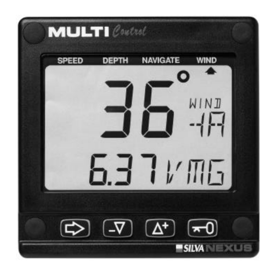
FUNCTION OVERVIEW Function overview The functions in the Multi Control instrument are divided into 4 pages: SPEED, DEPTH, NAVIGATE and WIND. The selected page is indicated by the LCD arrow at top of the display. Each page has 2 types of functions that can be displyed together: 1. -
Page 28: Speed Functions - Contents
SPEED FUNCTIONS CONTENTS SPEED FUNCTIONS 6.1 SPEED main-function..................28 6.2 SPEED sub-functions ..................28 6.2.1 TRIP LOG (TRP)..................28 6.2.2 TOTAL LOG (LOG)..................28 6.2.3 START TIMER (STA) .................. 28 6.2.4 TIMER ......................28 6.2.5 DISTANCE (DST)..................28 6.2.6 AVERAGE SPEED (AVS)................28 6.2.7 DAMPING (SEA).................. -
Page 29: Speed Main-Function
SPEED FUNCTIONS SPEED functions SPEED main-function Boat speed through the water. Unit available in knots (KT), km/h (Kh) or miles/h (Mh) (See 12.1.2,C11). If a navigator is connected, speed over ground (SOG) can be displayed. (See 12.1,C11 and C13). SPEED sub-functions 6.2.1 TRIP LOG (TRP) 0-199,99 NM, only displayed in NM. - Page 30 SPEED FUNCTIONS Default value is (LOW), for use in calm sea. But if the sea is rough, you may want to ”stabilise” the readout on the display, then select (MID) or (MAX). Damping is set separately for each instrument. 6.2.8 DEPTH (unit/DPT) Depth from the water surface or the keel depending on calibration setting (See 12.2.3, C22).
-
Page 31: Depth Functions - Contents
DEPTH FUNCTIONS CONTENTS DEPTH FUNCTIONS 7.1 DEPTH main-function..................31 7.2 DEPTH sub-functions ..................31 7.2.1 SHALLOW ALARM (SHA) ................31 7.2.2 DEPTH ALARM (DEA) ................31 7.2.3 ANCHOR ALARM (ANC) ................31 7.2.4 TEMPERATURE (TMP)................32 7.2.5 BATTERY (BAT) ..................32 7.2.6 BOAT SPEED (BSP/unit) ................ -
Page 32: Depth Main-Function
DEPTH FUNCTIONS Depth functions General information Alarm on = minute sign ( ´ ) displayed above the last depth digit in the sub-function. Alarm off = no minute sign ( ´ ) displayed. The alarms will be triggered, if the actual depth becomes less (shallow alarm), or more (depth alarm), than the set depth value. -
Page 33: Temperature (Tmp)
DEPTH FUNCTIONS You can either store the suggested values or set your own values. The logic is that when you are at anchor, the alarm will warn you if the boat is drifting towards deeper or shallower water. (See 7.4). 7.2.4 TEMPERATURE (TMP) Water temperature. -
Page 34: Set And Turn On Shallow (Sha) And Depth Alarm (Dea)
DEPTH FUNCTIONS Set and turn on shallow (SHA) and depth alarm (DEA) Select shallow (SHA) or depth (DEA) alarm, press KEY. The first digit in the previous value flashes. If you want to reset the previous value to zero (0), Press DOWN and UP together. -
Page 35: Navigation Functions - Contents
NAVIGATION FUNCTIONS CONTENTS NAVIGATION FUNCTIONS 8.1 NAVIGATION main-function ................35 8.2 NAVIGATION sub-functions ................35 8.2.1 STEER REFERENCE (Pilot OFF)..............35 8.2.2 STEER VALUE (STR) ................. 35 8.2.3 DAMPING (SEA)..................35 8.2.4 (SOG) and (COG) ..................35 8.2.5 (BTW) and (DTW)..................35 8.2.6 CROSS TRACK ERROR (XTE) .............. -
Page 36: Navigation Main-Function
NAVIGATION FUNCTIONS NAVIGATION functions NAVIGATION main-function Heading 000° to 359°. Heading true (HT) or heading magnetic (HM) can be displayed if the compass transducer is connected. (See 12.3, C32, C47). If a navigator is connected, course over ground (CG) can be selected instead of compass heading. -
Page 37: Steer Reference (Pilot)
Figure of merit (F) is a factor for the GPS reception quality on a scale from 1 to 9 where F1 = best reception and F9 = no reception. This function is only valid if a Nexus GPS receiver is connected to the Nexus Network. Steer reference (Pilot) The sub-function (Pilot) is intended to be used together with the optional analogue instrument steer pilot (Art. -
Page 38: Overview Of Steer Reference
Automatic waypoint, corrected for drift and current (AWA)=Apparent wind angle Manual (OFF)=Steer pilot off When any steer reference function is activated, the text on the display will be copied and shown on all Multi Control instruments in your Nexus Network. -
Page 39: Steer Reference (Mem)
(Pilot OFF) function. (Available from Server software version 1.9.) 8.3.3 Steer reference (BTW) This function requires the Nexus or NMEA compass transducer and a Nexus GPS or NMEA navigator. When selected, the function displays (BTW) and the analogue steer pilot instrument displays the difference between the compass heading and the bearing to waypoint (BTW). -
Page 40: Steer Reference (Cts)
NAVIGATION FUNCTIONS 8.3.4 Steer reference (CTS) This function requires log transducer, Nexus or NMEA compass transducer , Nexus GPS or NMEA navigator. When selected the function displays (CTS) and the analogue steer pilot instrument displays the difference between the compass heading and the bearing to waypoint (CTS) including set and drift. -
Page 41: Store And Edit A Waypoint (Edit Wp)
When a Nexus Autopilot is activated in wind mode, the (AWA) function on the Multi Control instrument can be used to perform an automatic tack. The minus sign ( - ) in front of the wind angle value = port side. -
Page 42: Store Present Position
Nexus Network which is keeping the waypoints in memory, but the waypoints can be reached from all instruments. If a portable Nexus GPS is connected, the Server takes over the navigation. If a Nexus GPS Navigator instrument (art no 21032) and... -
Page 43: Create A Sailplan (Goto Wp)
NAVIGATION FUNCTIONS If the longitude is more than 99° East or West the cursor for the 100:th digit flashes. If the 100:th digit is not displayed, press UP to activate it. To enter the new longitude co-ordinates, and to select hemisphere East (E) or West (W), press MODE, DOWN and UP as required. -
Page 44: Go To Waypoint
The (Go FROM) position is mainly used to define your track line, to calculate XTE etc. When the Nexus Network is set to be a repeater for an external NMEA navigator which is performing the navigation, you can display the waypoint in the (Goto WP) function, but you can not edit a waypoint other than in the NMEA navigator. -
Page 45: Go To Waypoint, From Other Than Your Present Position
NAVIGATION FUNCTIONS To add waypoints/legs to the sailplan, press UP to display (Goto NXT). To unlock and add waypoints/legs, press KEY and repeat the above described process. To exit the (Goto WP) function, press MODE. When you arrive at a waypoint in the sailplan, a series of automatic actions take place: The audible and visual arrival alarm is triggered. -
Page 46: Cancel A Leg In The Sailplan
NAVIGATION FUNCTIONS To start navigation to waypoint number (06), continue from above example and press UP until (Goto NXT) is displayed. To unlock the value, press KEY. To change from waypoint number (05) to (06), press UP. To store the new value, press KEY. From waypoint (05) to (06) the bearing is 345°... -
Page 47: Arrival Alarm
Factory setting radius value is 0.10 nautical mile. (See 12.3.12, C41). When the audible alarm is triggered (beeps 3 times), the text (ArriVAL) flashes 3 times on all connected Multi Control instruments. After the arrival alarm the instrument will revert to the previous displayed function. -
Page 48: Wind Functions - Contents
WIND FUNCTIONS CONTENTS WIND FUNCTIONS 9.1 WIND Main-function .................... 48 9.2 WIND Sub-functions.................... 48 9.2.1 APPARENT WIND SPEED (AWS) .............. 48 9.2.2 DAMPING (SEA)..................49 9.2.3 TRUE WIND SPEED TWS ................49 9.2.4 GEOGRAPHIC WIND DIRECTION ............. 49 9.2.5 VELOCITY MADE GOOD (VMG) ..............50 9.2.6 TACTICAL FUNCTION (TAC).............. -
Page 49: Wind Main-Function
WIND FUNCTIONS Wind functions WIND Main-function Apparent wind angle (AWA), true wind angle (TWA) 000° - 359°, apparent wind speed (AWS) or true wind speed (TWS): The main-function WIND, allows you to display wind angle or wind speed, true or apparent. The wind angle is indicated by a symbol to the right of the wind angle value: = Wind from port side. -
Page 50: Damping (Sea)
WIND FUNCTIONS 9.2.2 DAMPING (SEA) Damping of wind information. Controls the response time of wind changes. To change damping, press KEY. To select damping level, press UP and select from: LOW) 1 sec, (MID) 5 sec and (MAX) 22 sec. To store the selected value, press KEY. Factory value is (LOW), for use in calm sea. -
Page 51: Tactical Function
= heeling to port side. The Server will compensate the wind angle and the wind speed errors due to heeling. The compensation is already implemented in the Nexus Network, but a transducer to indicate roll is not yet available. Tactical function This function requires a compass transducer and displays course memory. - Page 52 WIND FUNCTIONS changed compared to the wind, that is you will be changing your heading due to the wind shifts. The tactical function will give you a fast and exact information about any wind shift compared to the magnetic heading. Select sub-function (TAC).
-
Page 53: Man Over Board (Mob) Function
(MOB) button. (See 2.4.1). If only a compass and a speed transducer is connected, dead reckoning (MOB) will be displayed on both the Multi Control and the SPEED Log instruments. Dead reckoning (MOB) is also a very useful information, since a person in the water will drift almost as fast as the boat. -
Page 54: Move And Lock A Sub-Function
CUSTOMISE YOUR DISPLAY Customise your display All sub-functions are organised in a list under the main-function. The first location in the sub-function list is an empty display. You can have your favourite sub-function moved in the same sub- function list, or copied and locked to any other page. 11.1 Move and lock a sub-function Example: In SPEED page, move and lock the sub-function depth... -
Page 55: Cancel A Moved Or Locked Sub-Function
CUSTOMISE YOUR DISPLAY 11.4 Cancel a moved or locked sub-function Example: To cancel the previous moved sub-function true wind speed (TWS) from SPEED page. Select the new combination, SPEED page and sub-function (TWS). Press MODE and KEY together. All digits flash. To cancel the moved sub-function, press DOWN and UP together. -
Page 56: Calibration - Contents
CALIBRATION CONTENTS CALIBRATION 12.1 Calibration of speed C10 .................. 57 12.1.1 C10 Return (RET) ..................57 12.1.2 C11 (Unit KTS)..................57 12.1.3 C12 (1.25 CAL) ..................57 12.1.4 C13 (OFF SOG)..................58 12.2 C20, calibration of depth..................58 12.2.1 C20 (RET)....................58 12.2.2 C21 (Unit m) ..................... - Page 57 CALIBRATION 12.6 C70, calibration of Network and NMEA .............. 63 12.6.1 C70 (RET)....................63 12.6.2 C71 (On KEY) ................... 63 12.6.3 C72 (d0 SEA).................... 63 12.6.4 C73 (OFF WPR) ..................64 12.6.5 C74 (On WPT) ..................64 12.6.6 C75 (OFF NAV)..................64 12.6.7 C76 (OFF CMP) ..................
-
Page 58: Calibration Of Speed C10
CALIBRATION Calibration To get the most out of your Nexus Network, it is important to carefully calibrate the Network. The calibration values are stored in a non volatile memory. To access calibration mode, press and hold KEY more than 2 seconds. -
Page 59: C20, Calibration Of Depth
CALIBRATION 12.1.4 C13 (OFF SOG) Select speed transducer to be displayed as main-function under SPEED. (OFF) = Boat speed through the water from log transducer. (ON) = Speed Over Ground (SOG) from navigator. 12.2 C20, calibration of depth 12.2.1 C20 (RET) To return to normal mode, press KEY. -
Page 60: C32 (00.0 Var)
CALIBRATION 12.3.3 C32 (00.0 VAR) Magnetic variation. Maximum +/- 99.9°. Easterly variation = underlining ( _ ) sign. Westerly variation = minus ( - ) sign. The local magnetic variation is usually printed in the sea chart. 12.3.4 C33 (Auto DEV) Automatic compass deviation, (see 12.4.1). -
Page 61: Compass Calibration
(OFF) = All headings and bearings will be true. Note a: In the (Goto WP) function, the bearing for every leg will always be displayed as true bearing. Note b: The setting is only affects the independent Multi Control instrument in which is set. 12.4 12.4 Compass calibration... -
Page 62: Automatic Compass Deviation Check (Auto Chk)
CALIBRATION If the deviation is not corrected, an error message will be displayed. To verify the automatic compass deviation, perform an automatic compass check (Auto CHK), (see 12.4.2). Note: You will get the best result in calm water with a smooth turn on the steering wheel independently of how the circle is performed. -
Page 63: C50, Calibration Of Wind
Select type of heading transducer, compass or navigator (COG), to be displayd as main-function under NAVIGATE. When COG is available (Nexus or NMEA), and no compass transducer is connected, you can set C75 to (ON), COG will also be used to compute TWD (true wind direction) 12.5.3... -
Page 64: C70, Calibration Of Network And Nmea
C72 (d0 SEA) Damping of speed and course over ground (SOG/COG), affecting the complete Nexus Network and NMEA output. d0 = no damping. d1 = 2 sec, d2 = 5 sec, d3 = 10 sec, d4 = 20 sec, d5 = 40 sec, d6 = 1.20 min, d7 = 2.40 min, d8 = 5 min and d9... -
Page 65: C73 (Off Wpr)
By the term ”navigating”, we mean the active instrument in which the waypoint memory is used to calculate the navigation data, i.e. BTW, DTW etc. There can only be one instrument on the Nexus Network which is navigating. (OFF) = The Server is navigating. -
Page 66: Nmea
The Server supports 29 different NMEA sentences. This means you can select up to 16 of the 29 available NMEA sentences. The Nexus Network uses the NMEA 0183 sentences, version 1.5 and 2.0. The number in brackets, example (C79), is the calibration code for the factory slot number given to the NMEA sentence. - Page 67 CALIBRATION (VLW) Distance travelled through the water (C87) (VPW) Speed relative to the wind (C88) (VTG) Distance made good and distance over ground. (C89) (VWR) Apparent wind speed and wind direction (C90) (VWT) True wind speed and direction (C92) (WCV) Waypoint closure velocity (C93) (WPL)
-
Page 68: Change Nmea Sentences Out From Server
To select the sentence, press DOWN or UP until found. To lock the selected sentence, press KEY. One of the advantages with the Nexus Network is the very fast transmission speed of data compared to the relatively slow NMEA standard (about 10 times faster). Therefore we recommend that you use Nexus instruments and transducers for better accuracy. -
Page 69: Receive Nmea Sentences In To Server
1) Position related data: Position, SOG/COG, time, and a limited amount of satellite status if a GPS is connected. The information is read if no other Nexus GPS is connected. If a Nexus GPS is connected, it will take over the navigation. -
Page 70: Special Nmea Sentences
PC. One contains TBS (target boat speed), the other CAD (customised angle data ) and CFD (customised fixpoint data ). These 3 data are retransmitted on the Nexus Network and can be displayed as a sub-function on the Multi Control instrument. -
Page 71: Maintenance And Fault Finding
13.2 Fault finding Before you contact your Nexus dealer, and to assist your dealer to give you a better service, please check the following points and make a list of: •... - Page 72 OK, If the voltmeter shows 0 or 5 V DC at both measuring points, the transducer or the connections are defect. Contact you Nexus dealer with this information. Make sure the transducer is aligned correctly, (see 12.5.6, C54).
- Page 73 MAINTENANCE AND FAULT FINDING 4. Navigation: Which instrument is navigating? (See 12.6, C75) C75 (OFF) = The Server is navigating. C75 (ON) = The NMEA navigator is navigating. If problem with NMEA IN to Server, (see 12.7 and 12.6.4). If problem with NMEA OUT from Server, (see 12.6.7 and 12.6.5).
- Page 74 13.2.3 Error messages The following error messages can appear on the display: ERROR 2 Nexus Network is missing, check colour coded connections ERROR 3 No data received within a given time. ERROR 10 Range error caused by bad format e.g. 17° 70' East.
-
Page 75: Specifications
14.2 Nexus databus introduction and user policy Introduction: The Nexus data bus is a multi talker multi receiver data bus specially designed for marine navigation applications. It utilises the RS485 standard with up to 32 senders and/or receivers to form a Local Area Network. -
Page 76: Optional Accessories
20721 Mast Top Unit, 22 m ( 72 ft) cable 20860 Fluxgate compass, 8 m (26 ft) cable 21000 GPS Antenna, Nexus/NMEA, fix, 10 m ( 33 ft) cable 21117 GPS Compass XL1000, portable, 21170 GPS Navigator XL300, portable, Nexus inboard hydraulic Autopilot... - Page 77 SPECIFICATIONS 21248 Nexus FD interface. PC interface with 1m (3.3 ft) cable. Includes a 3½”disc. with software for waypoint editing and a data bus manager and NMEA interface 19763 Push button for Tactical and MOB function 21154 High Speed Paddle wheel, up to 40 KTS...
-
Page 78: 14.5 Abbreviations
SPECIFICATIONS 14.5 Abbreviations Abbreviation. Description Angle ADJust ANChor ANChor alarm Arrival Arrival Arrival Circle AVerage Speed Apparent Wind Angle Apparent Wind Speed BATtery BeauFort Bearing Original Destination Boat Speed Bearing To Waypoint Celsius Communaute Europèenne Calibrate 10 Calibrate Course over Ground CHecK CLeaR Course Made Good... - Page 79 SPECIFICATIONS HeaDing Magnetic HeaDing True Heading Magnetic Heading True Identity Init Initiation Insert Insert Kilometre per hour KnoTs KnoTS Local LATitude Liquid Crystal Display Local Geodetic Datum LONgitude metres per second MEMory Miles per hour Magnetic North Man Over Board metre North NAVigate...
- Page 80 SPECIFICATIONS VARiation Velocity Made Good West Waypoint Closure Velocity Waypoint Cross Track Error Minus Plus Wind from port side Wind from starboard side The boat is left of the desired track The boat is right of the desired track...
-
Page 81: Warranty
WARRANTY WARRANTY GENERAL All our products are designed and built to comply to the highest class industry standards. If the products are correctly installed, maintained and operated, as described in the installation and operation manual, they will provide long and reliable service. Our international Network of distributors can provide you with the information and assistance you may require virtually anywhere in the world. - Page 82 WARRANTY File id: WARRANTY CARD TO BE RETURNED TO YOUR NATIONAL DISTRIBUTOR OWNER: Name: Street : City/Zip Code : Country: Product name: Serial number: Date of purchase:_______________ Date installed ________________ Dealers stamp: Tick here if you do not wish to receive news about future products...
Need help?
Do you have a question about the Multi Control and is the answer not in the manual?
Questions and answers