Table of Contents
Advertisement
Advertisement
Table of Contents

Related Manuals for DigiPos DS-800


Summary of Contents for DigiPos DS-800
- Page 1 DS-800 ::: Receipt Printer User’s manual :::...
-
Page 2: Table Of Contents
All specifications are subjected to change without notice TABLE OF CONTENTS 1. Parts Identifications 2. Setting up the printer 2.1 Unpacking 2.2 Connecting the cables 2.3 Loading the roll paper 2.4 Dip switch setting 3. Control panel and other functions 3.1 Control panel 3.2 Error Indicating 4. -
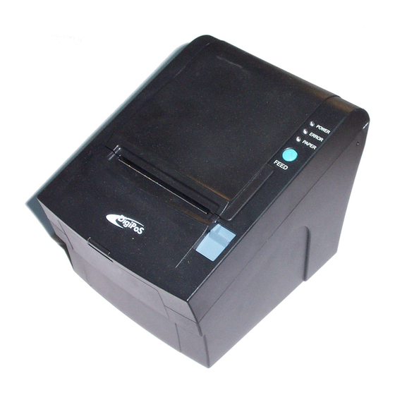
Page 3: Parts Identifications
1. Parts Identifications Page - 2-... -
Page 4: Setting Up The Printer
2. Setting Up the Printer 2-1. Unpacking Your printer box should include these items. If any items are damaged or missing, please contact your dealer for assistance. Page - 3-... -
Page 5: Connecting The Cables
Adaptor (Option) Interface Cable (Option) 2-2. Connecting the Cables You can connect up the cables required for printing to the printer. They all connect to the connector panel on the back of the printer, which is shown below : Page - 4-... - Page 6 Before connecting any of the cables, make sure that both the printer and the computer are turned off. Page - 5-...
-
Page 7: Interface Connector
2-2-1. Interface Connector <D-SUB 25 Female Serial Port> <D-SUB Centronics Parallel Port> <4Pin “ B” Type USB Port> - Serial interface SIGNAL DESCRIPTION Output Printer transmit data line RS-232C level Input Printer receive data line RS-232C level 4, 20 Output Printer handshake to host line RS-232C level Input Data Send Ready... -
Page 8: Centronics Parallel Interface
SIGNAL DESCRIPTION DATA- Printer transmit data line DATA+ Printer transmit data line System Ground - Centronics Parallel interface SIGNAL DESCRIPTION STROBE- Input Synchronize signal Data received DATA0~7 Input/Output Data bit Transmitted 0~7 ACK- Output Data receiving completed. BUSY Output Impossible to print of data receiving. Output Paper empty SELECT... -
Page 9: Loading The Roll Paper
SIGNAL DESCRIPTION Signal GND Drawer kick-out drive signal 1 Output Drawer open/close signal Input +24V Drawer kick-out drive signal 2 Output Signal GND 2-3. Loading the Roll Paper Notes: Be sure to use paper rolls that meet the specifications. Do not use paper rolls that have the paper glued to the core because the printer cannot detect the paper end correctly. - Page 10 3. Remove the used paper roll core if there is one inside. 4. Insert new paper roll as shown. 5. Be sure to note the correct direction that the paper comes off the roll. Page - 9-...
-
Page 11: Dip Switch Setting
6. Pull out a small amount of paper, as shown. Then, close the cover. 7. Tear off the paper as shown. 2-4. DIP SWITCH SETTING The printer is set up at the factory to be appropriate for almost all users. It does, however, offer some settings for users with special requirements. - Page 12 following tables. ※Note : Power off. And open the cover of Dip Switch and change setting. 2-4-1. Serial Interface Specification DIP Switch Set 1 Functions FUNCTION DEFAULT Data Receive Error Ignore Print “ ?” Hexadecimal HEXDUMP NORMAL Hand Shaking XON/OFF DTR/DSR Data Length 7bits...
-
Page 13: Parallel Interface Specification
FUNCTION SW-4 SW-5 Epson (TM-88) Paper low detect FUNCTION Paper Low Detect Do not Detect 2-4-2. Parallel Interface Specification DIP Switch Set 1 Function FUNCTION DEFAULT Reserved Hexadecimal HEXDUMP NORMAL Reserved Reserved Parallel mode UNIDIRECTION BIDIRECTION Reserved Baud rate selection Transmission speed SW-7 SW-8... - Page 14 Cutter FUNCTION Remarks Cutter FULL CUT PARTIAL CUT Only Epson mode Emulation FUNCTION SW-4 SW-5 Epson (TM-88) Paper low detect FUNCTION Paper Low Detect Do not Detect ☞ CAUTION: Turn off the printer while removing the DIP switch cover to prevent an electric short, which can damage the printer.
- Page 15 3. Set the switches using a pointed toll, such as tweezers or a small screwdriver. 4. Replace the DIP switch cover. Then, secure it with the screw. The new settings take effect when you turn on the printer. Page - 14-...
- Page 16 ☞ CAUTION: When the paper is jammed with cutter, the top cover might be stuck. In this case, repeat power on and off several times. If the top cover is still stuck, please follow the steps to release the papers from jamming. 1.
-
Page 17: Control Panel And Other Functions
3. Control panel and other functions. 3-1. Control panel You can control the basic paper feeding operations of the printer with the button on the control panel. The indicator lights help you to monitor the printer’ s status. Control Panel PO W ER ER R O R PAPER... -
Page 18: Error Indicating
Press the FEED button once to advance paper one line. You can also hold down the FEED button to feed paper continuously. 3-2. Error indicating This section explains the different patterns signaled by the two LED indicators located on the top cover of the printer. -
Page 19: Hexadecimal Dump
printer to begin the self-test. The Self Test prints the printer settings and then prints the following, Cuts the paper, and pauses. (Error LED On) Self test Printing Please press the PAPER FEED button. 3. Press the FEED button to continue printing. The printer prints a pattern using the built-in character set. -
Page 20: Specifications
4. Turn on the printer. 6. Specifications Important! When using a printer power supply other than optional AC adaptor (HT-U1135, LSE 9901B2460), be sure that the following cautions are observed. Use a power supply (Limited Power Supply) of DC 24V±10% and more than 1.5A. Be careful about installing the printer in an area where there is noise. -
Page 21: Certification
6-3. Certification (1)FCC PART15 CLASS A (2)CE EMCD/LVD (3)UL/cUL (4)MIC 7. Command List Command Function REMARKS Horizontal tab Print and line feed Print and carriage return Print end position label to start printing Cancel print data in page mode DLE EOT Real-time status transmission DLE ENQ Real-time request to printer... - Page 22 ESC = Select peripheral device ESC ? Cancel user-defined characters ESC @ Initialize printer ESC D Set horizontal tab positions ESC E Select emphasized mode ESC G Select double-strike mode ESC J Print end feed paper using minimum units ESC L Select page mode ESC M Select character font...
- Page 23 GS f Select font for HRI characters GS h Set bar code height GS k Print bar code GS r Transmit status GS v 0 Print raster bit image GS w Set bar code width < Add > ESC i Full cut ESC m Partial cut...
- Page 24 :: MEMO :: Page - 23-...
- Page 25 :: MEMO :: Page - 24-...
- Page 26 :: MEMO :: Page - 25-...
- Page 27 Page - 26-...
Need help?
Do you have a question about the DS-800 and is the answer not in the manual?
Questions and answers