
Summary of Contents for Alto BK 2.0
- Page 1 User's Manual BK 2.0 COMPRESSOR /LIMITER /GATE www.altoproaudio.com Version 2.0 Dec. 2002 English English...
- Page 2 SAFETY RELATED SYMBOLS Never cut off the internal or external protective grounding wire or disconnect the wiring of protective grounding terminal. CAUTION RISK OF ELECTRIC SHOCK Operating Conditions DO NOT OPEN This apparatus shall not be exposed to dripping or spl- The symbol is used to indicate that some hazard- ashing and that no objects filled with liquids, such as ous live terminals are involved within this apparatus,...
- Page 3 LTO BK 2.0 is the result of many hours of listening and tests involving common people, area experts, musicians and technicians.
-
Page 4: Table Of Contents
TABLE OF CONTENTS 1. INTRODUCTION............................4 2. THE CONCEPT BEHIND..........................4 2.1 Some technical stuff 2.2 Voltage Controlled Amplifier (VCA) 2.3 Inputs 3. CONTROLS..............................6 3.1 Expander/Gate Section 3.2 Compressor Section 3.3 Dynamic Enhancer Section 3.4 The Rear Panel 4. READY TO ROLL?............................9 4.1 Expander/Gate Section 4.2 Compressor Section 4.3 Limiter Section... -
Page 5: Introduction
The AUTO Function Your BK 2.0 includes and AUTO function switch on the front panel. Thanks to the AUTO function attack and release times of the program materials are automatically analysed. Then the dynamic range of the program is heavily compressed in a very musical way so that there will not be any audible breathing or pumping effect. - Page 6 2.1.2 Introducing Audio Dynamics The human ear can detect the noise generating by falling leaves as well as the roar generated by the taking off space shuttle. Unfortunately no analog, nor digital device can reproduce such wide spectrum. Please look at Chart. 1 and you will see the difference if dynamic capacity of various devices when compare to the human ear.
-
Page 7: Voltage Controlled Amplifier (Vca)
2.2 Voltage Controlled Amplifier (VCA) The VCA is the soul of the BK 2.0 and it is one of the best components available today in his category thanks to its excellent performances in terms of distortion, linearity, noise and temperature stability. -
Page 8: Compressor Section
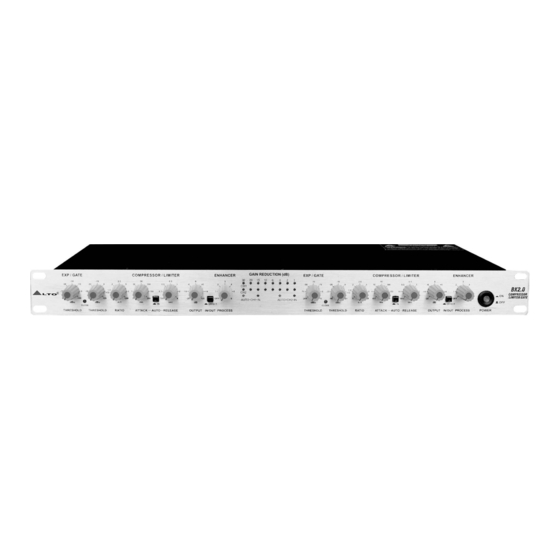
2.Close LED This LED illuminates when expansion occurs. 3.2 Compressor Section GAIN REDUCTION (dB) COMPRESSOR / LIMITER ENHANCER AUTO CH1 IN AUTO CH2 IN EFFECT RATIO ATTACK AUTO RELEASE THRESHOLD OUTPUT IN/OUT PROCESS Pic.3: Controls of the Compressor/Limiter section 3. EFFECT Switch Engage this switch to activate the corresponding channel. - Page 9 SIDECHAIN CHANNEL 1 SIDECHAIN Pic.5: The Back Panel Layout Of The BK 2.0 12. Fuse holder / Voltage Selector This is a dual voltage unit. Before you attempt to connect and operate the unit, please make sure that your local voltage matches the voltage on the fuse-holder cover.
-
Page 10: Ready To Roll
It simply cut-off the entire signal below a certain set threshold. The BK 2.0 is equipped with a new kind of expander, the SRC (Smart Ratio Control). The ratio of the SRC is automatically adjusted according to the audio signal level. - Page 11 Anyway, our advice is always to begin the process with longer attack times. Then you can start gradually to reduce the attack time. IN the BK 2.0 the attack time can be set in a range of 1 to 200 milliseconds.
-
Page 12: Limiter Section
4.2.8 Gain Reduction Meter This consists of 8 LED on the front of the BK 2.0. Through this Led meter you can visualise the amount of gain reduction at any given time. Chart.6: The effect of a compressor can be expressed as the amount of gain reduction that is taking place for any given input 4.3 Limiter Section... - Page 13 Wiring Configuration Both types of connectors available on BK 2.0 can be wired in balanced and unbalanced modes. Please see following drawing for details: For 1/4" TRS jack 1/4"TRS jack 1/4"TRS jack Unbalanced input Balanced input For XLR connector...
-
Page 14: Rack Mounting
Please allow at least an additional 4" depth for the connectors on the rear panel. Be sure that there is enough air space around the unit for sufficient ventilation and please do not place the BK 2.0 Compressor /Limiter /Gate on... -
Page 15: Technical Specifications
6. TECHNICAL SPECIFICATIONS Type Active balanced XLR and 1/4"JACK Impedance AUDIO INPUT 60k ohm balanced Maximum input level +21 dBu balanced and unbalanced Type XLR and 1/4" JACK Impedance < 40k ohm unbalanced Maximum output level +21 dBu Frequency response 20Hz to 20KHz at +0,- 1dB AUDIO OUTPUT THD +N% @ 1kHz, +4dBu... -
Page 16: Block Diagram
7. BLOCK DIAGRAM Chart.8: Block diagram of the BK 2.0... -
Page 17: Warranty
8. WARRANTY 1. WARRANTY REGISTRATION CARD To obtain Warranty Service, the buyer should first fill out and return the enclosed Warranty Registration Card within 10 days of the Purchase Date. All the information presented in this Warranty Registration Card gives the manufacturer a better understanding of the sales status, so as to purport a more effective and efficient after-sales warranty service. - Page 18 SEKAKU ELECTRON IND. CO., LTD NO.1, LANE 17, SEC. 2, HAN SHI WEST ROAD, TAICHUNG, 401 TAIWAN http://www.altoproaudio.com Tel:886-4-22313737 email: alto@altoproaudio.com Fax:886-4-22346757 All rights reserved to ALTO. All features and content might be changed without prior notice. Any photocopy, translation, or reproduction of part of this manual without written permission is forbidden.
Need help?
Do you have a question about the BK 2.0 and is the answer not in the manual?
Questions and answers