Table of Contents
Advertisement
Advertisement
Table of Contents
Troubleshooting

Related Manuals for Gigabyte GA-X79-UD3


Summary of Contents for Gigabyte GA-X79-UD3
- Page 1 GA-X79-UD3 User's Manual Rev. 1001 12ME-X79UD3-1001R...
- Page 2 Motherboard GA-X79-UD3 Motherboard GA-X79-UD3 Oct. 28, 2011 Oct. 28, 2011...
-
Page 3: Identifying Motherboard Revision
GIGABYTE's prior written permission. Documentation Classiications In order to assist in the use of this product, GIGABYTE provides the following types of documentations: „ For quick set-up of the product, read the Quick Installation Guide included with the product. -
Page 4: Table Of Contents
Table of Contents Box Contents ........................6 Optional Items .........................6 GA-X79-UD3 Motherboard Layout..................7 GA-X79-UD3 Motherboard Block Diagram ..............8 Chapter 1 Hardware Installation ..................9 Installation Precautions ................... 9 Product Speciications ................... 10 Installing the CPU and CPU Cooler............... 13 1-3-1 Installing the CPU ....................13 1-3-2 Installing the CPU Cooler ..................15... - Page 5 Chapter 3 Drivers Installation ..................59 Installing Chipset Drivers ................59 Application Software ..................60 Technical Manuals ..................60 Contact......................61 System ......................61 Download Center ................... 62 New Utilities ....................62 Chapter 4 Unique Features ...................63 Xpress Recovery2 ..................63 BIOS Update Utilities ..................
-
Page 6: Box Contents
Box Contents GA-X79-UD3 motherboard Motherboard driver disk User's Manual Quick Installation Guide Four SATA cables I/O Shield One 2-Way SLI bridge connector One 3-Way SLI bridge connector One 4-Way SLI bridge connector One 2-Way CrossFireX bridge connector The box contents above are for reference only and the actual items shall depend on the product package you obtain. -
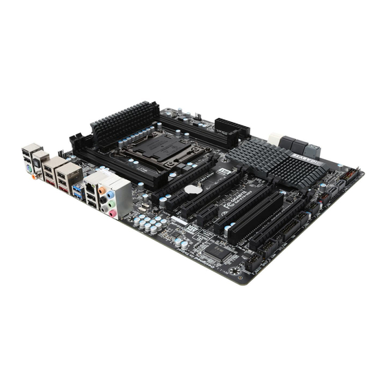
Page 7: Ga-X79-Ud3 Motherboard Layout
GA-X79-UD3 Motherboard Layout CPU_FAN KB_MS_USB ATX_12V_2X4 SYS_FAN1 R_SPDIF LGA2011 USB_ESATA2 SYS_FAN2 USB_ESATA1 R_USB30 Fresco FL1009 USB_LAN Marvell 88SE9172 AUDIO PCIEX16_1 Fresco ® Intel GbE LAN FL1009 PCIEX_1 SATA3 M_BIOS B_BIOS PCIEX8_1 CODEC PCIEX1_2 ® GA-X79-UD3 Intel GSATA3 Marvell PCIEX16_2 88SE9172... -
Page 8: Ga-X79-Ud3 Motherboard Block Diagram
GA-X79-UD3 Motherboard Block Diagram 1 PCI Express x16 2 PCI Express x8 CPU CLK+/- (100 MHz) 1 PCI 1 PCI Express x16 Express x8 DDR3 2133/1866/1600/1333/1066 MHz LGA2011 CPU 4 Channel Memory PCIe CLK (100 MHz) DMI 2.0 Switch PCIe CLK... -
Page 9: Chapter 1 Hardware Installation
Chapter 1 Hardware Installation Installation Precautions The motherboard contains numerous delicate electronic circuits and components which can become damaged as a result of electrostatic discharge (ESD). Prior to installation, carefully read the user's manual and follow these procedures: • Prior to installation, make sure the chassis is suitable for the motherboard. •... -
Page 10: Product Speciications
2133/1866/1600/1333/1066 MHz memory modules Š Support for non-ECC memory modules Support for Extreme Memory Proile (XMP) memory modules Š (Go to GIGABYTE's website for the latest supported memory speeds and memory modules.) Š Audio Realtek ALC898 codec High Deinition Audio Š... - Page 11 Š Storage Interface 3 x Marvell 88SE9172 chips: 4 x SATA 6Gb/s connectors (GSATA3 6/7/8/9) supporting up to 4 SATA 6Gb/s devices Support for RAID 0 and RAID 1 2 x eSATA 6Gb/s connectors on the back panel, supporting up to 2 SATA 6Gb/s devices Support for RAID 0 and RAID 1 Š...
- Page 12 Support for Microsoft Windows 7/Vista/XP ® System Š Form Factor ATX Form Factor; 30.5cm x 24.4cm * GIGABYTE reserves the right to make any changes to the product speciications and product-related information without prior notice. Hardware Installation - 12 -...
-
Page 13: Installing The Cpu And Cpu Cooler
Read the following guidelines before you begin to install the CPU: • Make sure that the motherboard supports the CPU. (Go to GIGABYTE's website for the latest CPU support list.) • Always turn off the computer and unplug the power cord from the power outlet before installing the CPU to prevent hardware damage. - Page 14 B. Follow the steps below to correctly install the CPU into the motherboard CPU socket. • Before installing the CPU, make sure to turn off the computer and unplug the power cord from the power outlet to prevent damage to the CPU. •...
-
Page 15: Installing The Cpu Cooler
1-3-2 Installing the CPU Cooler Refer to the steps below to correctly install the CPU cooler on the motherboard. (Actual installation process may differ depending the CPU cooler to be used. Refer to the user's manual for your CPU cooler.) Step 1: Step 2: Apply an even and thin layer of thermal grease... -
Page 16: Installing The Memory
Make sure that the motherboard supports the memory. It is recommended that memory of the same capacity, brand, speed, and chips be used. (Go to GIGABYTE's website for the latest supported memory speeds and memory modules.) • Always turn off the computer and unplug the power cord from the power outlet before installing the memory to prevent hardware damage. -
Page 17: Installing A Memory
1-4-2 Installing a Memory Before installing a memory module, make sure to turn off the computer and unplug the power cord from the power outlet to prevent damage to the memory module. DDR3 and DDR2 DIMMs are not compatible to each other or DDR DIMMs. Be sure to install DDR3 DIMMs on this motherboard. -
Page 18: Installing An Expansion Card
Installing an Expansion Card Read the following guidelines before you begin to install an expansion card: • Make sure the motherboard supports the expansion card. Carefully read the manual that came with your expansion card. • Always turn off the computer and unplug the power cord from the power outlet before installing an expansion card to prevent hardware damage. -
Page 19: Setting Up Amd Crossfirex /Nvidia Sli Coniguration
/NVIDIA SLI Coniguration ™ Setting up AMD CrossFireX A. System Requirements The 2-Way CrossFireX and 2-Way SLI technologies currently support Windows 7, Vista, XP operating systems The 3-Way/4-Way CrossFireX/SLI technologies currently support Windows 7 and Vista operating systems A CrossFireX/SLI-supported motherboard with two/three/four PCI Express x16 slots and correct driver Two/three/four CrossFireX/SLI-ready graphics cards of identical brand and chip and correct driver (Current GPUs that support 3-Way/4-Way CrossFireX technology include the ATI Radeon HD 3800, HD 4800, HD 5800 series, and AMD Radeon HD 6800 and HD 6900 series. -
Page 20: Back Panel Connectors
Back Panel Connectors USB 2.0/1.1 Port The USB port supports the USB 2.0/1.1 speciication. Use this port for USB devices such as a USB key- board/mouse, USB printer, USB lash drive and etc. PS/2 Keyboard/Mouse Port Use this port to connect a PS/2 mouse or keyboard. Optical S/PDIF Out Connector This connector provides digital audio out to an external audio system that supports digital optical audio. - Page 21 Center/Subwoofer Speaker Out Jack (Orange) Use this audio jack to connect center/subwoofer speakers in a 5.1/7.1-channel audio coniguration. Rear Speaker Out Jack (Black) Use this audio jack to connect rear speakers in a 7.1-channel audio coniguration. Side Speaker Out Jack (Gray) Use this audio jack to connect side speakers in a 4/5.1/7.1-channel audio coniguration.
-
Page 22: Internal Connectors
Internal Connectors ATX_12V_2X4 CLR_CMOS F_PANEL CPU_FAN F_AUDIO SYS_FAN1/2/3/4 SPDIF_O SATA3 0/1 F_USB1/F_USB2/F_USB3 SATA2 2/3/4/5 F_USB30 GSATA3 6/7 COMA GSATA3 8/9 Read the following guidelines before connecting external devices: • First make sure your devices are compliant with the connectors you wish to connect. •... - Page 23 1/2) ATX_12V_2X4/ATX (2x4 12V Power Connector and 2x12 Main Power Connector) With the use of the power connector, the power supply can supply enough stable power to all the com- ponents on the motherboard. Before connecting the power connector, irst make sure the power supply is turned off and all devices are properly installed.
- Page 24 3/4) CPU_FAN/SYS_FAN1/SYS_FAN2/SYS_FAN3/SYS_FAN4 (Fan Headers) The motherboard has a 4-pin CPU fan header (CPU_FAN), two 4-pin (SYS_FAN1/SYS_FAN2) and two 3-pin (SYS_FAN3/SYS_FAN4) system fan headers. Most fan headers possess a foolproof insertion de- sign. When connecting a fan cable, be sure to connect it in the correct orientation (the black connector wire is the ground wire).
- Page 25 5) SATA3 0/1 (SATA 6Gb/s Connectors, Controlled by Intel X79 Chipset) The SATA connectors conform to SATA 6Gb/s standard and are compatible with SATA 3Gb/s and SATA 1.5Gb/s standard. Each SATA connector supports a single SATA device. The "SATA3 0" and "SATA3 1"...
- Page 26 7) GSATA3 6/7 (SATA 6Gb/s Connectors, Controlled by Marvell 88SE9172 Chip) The SATA connectors conform to SATA 6Gb/s standard and are compatible with SATA 3Gb/s and SATA 1.5Gb/s standard. Each SATA connector supports a single SATA device. The Marvell 88SE9172 chip supports RAID 0 and RAID 1.
-
Page 27: Battery/Clearing Cmos Jumper
9) BAT (Battery) The battery provides power to keep the values (such as BIOS conigurations, date, and time information) in the CMOS when the computer is turned off. Replace the battery when the battery voltage drops to a low level, or the CMOS values may not be accurate or may be lost. You may clear the CMOS values by removing the battery: Turn off your computer and unplug the power cord. -
Page 28: F_Panel Front Panel Header
11) F_PANEL (Front Panel Header) Connect the power switch, reset switch, speaker, chassis intrusion switch/sensor and system status indicator on the chassis to this header according to the pin assignments below. Note the positive and negative pins before connecting the cables. Message/Power/ Power Speaker... - Page 29 12) F_AUDIO (Front Panel Audio Header) The front panel audio header supports Intel High Deinition audio (HD) and AC'97 audio. You may connect your chassis front panel audio module to this header. Make sure the wire assignments of the module con- nector match the pin assignments of the motherboard header.
- Page 30 14) F_USB1/F_USB2/F_USB3 (USB 2.0/1.1 Headers) The headers conform to USB 2.0/1.1 speciication. Each USB header can provide two USB ports via an optional USB bracket. For purchasing the optional USB bracket, please contact the local dealer. Pin No. Deinition Power (5V) Power (5V) USB DX- USB DY-...
- Page 31 16) COMA (Serial Port Header) The COM header can provide one serial port via an optional COM port cable. For purchasing the op- tional COM port cable, please contact the local dealer. Pin No. Deinition NDCD- NSIN NSOUT NDTR- NDSR- NRTS- NCTS- NRI-...
- Page 32 Hardware Installation - 32 -...
-
Page 33: Chapter 2 Bios Setup
CMOS. To access the BIOS Setup program, press the <Delete> key during the POST when the power is turned on. To upgrade the BIOS, use either the GIGABYTE Q-Flash or @BIOS utility. • Q-Flash allows the user to quickly and easily upgrade or back up BIOS without entering the operating system. -
Page 34: Startup Screen
Startup Screen The following startup Logo screen will appear when the computer boots. Function Keys Function Keys: <TAB>: POST SCREEN Press the <Tab> key to skip the startup Logo. To turn off the startup Logo, refer to the instructions on the Full Screen LOGO Show item on page 51. -
Page 35: The Main Menu
A. The 3D BIOS Screen (Default) On GIGABYTE's uniquely designed 3D BIOS screen, you can use your mouse to move through the motherboard image and click to enter the function menu in each area for quick coniguration. For example, pass your mouse arrow over the CPU and memory sockets and enter the System Tuning menu to conigure CPU/memory frequency, memory timings, and voltage settings. - Page 36 BIOS Setup Program Function Keys <f><g> Move the selection bar to select a setup menu Move the selection bar to select an coniguration item on a menu <h><i> <Enter> Execute command or enter a menu <+>/<Page Up> Increase the numeric value or make changes <->/<Page Down>...
-
Page 37: M.i.t
M.I.T. Whether the system will work stably with the overclock/overvoltage settings you made is dependent on your overall system conigurations. Incorrectly doing overclock/overvoltage may result in damage to CPU, chipset, or memory and reduce the useful life of these components. This page is for advanced users only and we recommend you not to alter the default settings to prevent system instability or other unexpected results. - Page 38 M.I.T. Current Status This screen provides information on CPU/memory frequencies/parameters. Advanced Frequency Settings & BCLK/PCIe Clock Control Enables or disables the control of CPU base clock and PCIe bus frequency. Enabled will allow the Host Clock Frequency and Processor Base Clock items below to be conigurable. Note: If your system fails to boot after overclocking, please wait for 20 seconds for automated system reboot, or clear the CMOS values to reset the board to default values.
-
Page 39: Advanced Cpu Core Features
Advanced CPU Core Features & CPU Clock Ratio, CPU Frequency The settings under the two items above are synchronous to that under the same items on the Advanced Frequency Settings menu. & Internal CPU PLL Overvoltage Enabled allows CPU PLL voltage to operate at a higher value. Disabled allows CPU PLL voltage to operate at default value. - Page 40 & CPU Core Enabled (Note 1) Allows you to determine the number of CPU cores you want to enable. Auto lets the BIOS automatically conigure this setting. (Default: Auto) & Hyper-Threading Technology (Note 1) Allows you to determine whether to enable Hyper-Threading technology when using an Intel CPU that supports this function.
- Page 41 & Memory Frequency(Mhz) The irst memory frequency value is the normal operating frequency of the memory being used; the second is the memory frequency that is automatically adjusted according to the Host Clock Frequency, Processor Base Clock, and System Memory Multiplier settings. Advanced Memory Settings &...
- Page 42 & Channel Interleaving Enables or disables memory channel interleaving. Enabled allows the system to simultaneously access different channels of the memory to increase memory performance and stability. Auto lets the BIOS automatically conigure this setting. (Default: Auto) & Rank Interleaving Enables or disables memory rank interleaving.
- Page 43 Advanced Voltage Settings 3D Power Control - 43 - BIOS Setup...
- Page 44 & PWM Phase Control Allows you to automatically change the PWM phase according to the CPU load. The power-saving levels are (from lowest to highest): eXm Perf (Extreme Performance ), High Perf (High Performance), Balanced, Perf (Performance), Mid PWR (Mid Power), and Lite PWR (Light Power). Auto lets the BIOS automatically conigure this setting.
- Page 45 Lets the BIOS automatically conigure this setting and sets V-droop following Intel Auto speciications. (Default) +0.00m ~+12.00m Adjusts the V-droop value. & DDR CH(C/D) Voltage Loadline Calibration Allows you to conigure Load-Line Calibration for Channel C and Channel D memory voltage. This item allows you to adjust V-droop.
- Page 46 & DDR CH(A/B) Current Protection Allows you to set the current limit on Channel A and Channel B memory voltage for over-current protection in terms of percentage. The adjustable range is from 50.0% to 160.0%. Auto lets the BIOS automatically conigure this setting.
- Page 47 PC Health Status & Reset Case Open Status Disabled Keeps or clears the record of previous chassis intrusion status. (Default) Case Opened ield will show Enabled Clears the record of previous chassis intrusion status and the "No" at next boot. &...
- Page 48 & CPU Vcore/Dram Channel A/B Voltage/Dram Channel C/D Voltage/+5V/+12V+/CPU VTT Displays the current system voltages. & CPU Temperature/PCH Temperature/System Temperature Displays current CPU/Chipset/system temperature. & CPU Fan Speed/System Fan Speed Displays current CPU/system fan speeds. & CPU Warning Temperature Sets the warning threshold for CPU temperature. When CPU temperature exceeds the threshold, BIOS will emit warning sound.
- Page 49 Miscellaneous Settings & Isochronous Support Determines whether to enable speciic streams within the CPU and Chipset. This item is present only when you install a CPU that supports this feature. For more information about Intel CPUs' unique features, please visit Intel's website. (Default: Enabled) - 49 - BIOS Setup...
-
Page 50: System
System This section provides information on your CPU, memory, motherboard model, and BIOS version. You can also select the default language used by the BIOS and manually set the system time. & System Language Selects the default language used by the BIOS. &... -
Page 51: Bios Features
Enables or disables Numlock feature on the numeric keypad of the keyboard after the POST. (Default: Disabled) & Full Screen LOGO Show Allows you to determine whether to display the GIGABYTE Logo at system startup. Disabled skips the GIGABYTE Logo when the system starts up. (Default: Enabled) & PCI ROM Priority Allows you to determine which Option ROM to launch. -
Page 52: Administrator Password
& Init Display First Speciies the irst initiation of the monitor display from the installed PCI or PCI Express graphics cards . PCIe Slot 1 Sets the graphics card on the PCIEX16_1 slot as the irst display. (Default) PCIe Slot 2 Sets the graphics card on the PCIEX8_1 slot as the irst display. -
Page 53: Peripherals
Peripherals & LAN PXE Boot Option ROM Allows you to decide whether to activate the boot ROM integrated with the onboard LAN chip. (Default: Disabled) & LAN Controller Enables or disables the onboard LAN function. (Default: Enabled) If you wish to install a 3rd party add-in network card instead of using the onboard LAN, set this item to Disabled. - Page 54 & XHCI Hand-off Determines whether to enable XHCI Hand-off feature for an operating system without XHCI Hand-off support. (Default: Enabled) & EHCI Hand-off Determines whether to enable EHCI Hand-off feature for an operating system without EHCI Hand-off support. (Default: Disabled) &...
- Page 55 & GSATA Controller (Marvell 88SE9172 Chip, GSATA3 8 and GSATA3 9 connectors) Enables or disables RAID for the SATA controllers integrated in the Marvell 88SE9172 chip or conigures the SATA controllers to AHCI mode. IDE Mode Disables RAID for the SATA controllers and conigures the SATA controllers to IDE mode.
-
Page 56: Power Management
Power Management & AC BACK Determines the state of the system after the return of power from an AC power loss. Always Off The system stays off upon the return of the AC power. (Default) Always On The system is turned on upon the return of the AC power. Memory The system returns to its last known awake state upon the return of the AC power. - Page 57 S3(Suspend to RAM) Enables the system to enter the ACPI S3 sleep state. In S3 sleep state, the system appears to be off and consumes less power than in the S1 state. When signaled by a wake-up device or event, the system resumes to its working state exactly where it was left off.
-
Page 58: Save & Exit Setup
Save & Exit Setup & Save & Exit Setup Press <Enter> on this item and select Yes. This saves the changes to the CMOS and exits the BIOS Setup program. Select No or press <Esc> to return to the BIOS Setup Main Menu. &... -
Page 59: Chapter 3 Drivers Installation
• After "Xpress Install" installs all of the drivers, a dialog box will appear asking whether to install new GIGABYTE utilities. Click Yes to automatically install the utilities. Or click No if you want to manually select the utilities to install on the Application Software page later. -
Page 60: Application Software
Application Software This page displays all the utilities and applications that GIGABYTE develops and some free software. You can click the Install button on the right of an item to install it. Technical Manuals This page provides GIGABYTE's application guides, content descriptions for this driver disk, and the mother- board manuals. -
Page 61: Contact
Contact For the detailed contact information of the GIGABYTE Taiwan headquarter or worldwide branch ofices, click the URL on this page to link to the GIGABYTE website. System This page provides the basic system information. - 61 - Drivers Installation... -
Page 62: Download Center
The latest version of the BIOS, drivers, or applications will be displayed. New Utilities This page provides a quick link to GIGABYTE's lately developed utilities for users to install. You can click the Install button on the right of an item to install it. -
Page 63: Chapter 4 Unique Features
Chapter 4 Unique Features Xpress Recovery2 Xpress Recovery2 is a utility that allows you to quickly compress and back up your system data and perform restoration of it. Supporting NTFS, FAT32, and FAT16 ile systems, Xpress Recovery2 can back up data on PATA and SATA hard drives and restore it. - Page 64 Step 3: Step 4: When partitioning your hard drive, make sure to leave After the operating system is installed, click Start, unallocated space (10 GB or more is recommended; right-click the Computer and select Manage. Go to actual size requirements vary, depending on the Disk Management to check disk allocation.
- Page 65 D. Using the Restore Function in Xpress Recovery2 Select RESTORE to restore the backup to your hard drive in case the system breaks down. The RESTORE option will not be present if no backup is created before. E. Removing the Backup Step 1: Step 2: After the backup ile is removed, no backup image ile...
-
Page 66: Bios Update Utilities
4-2-1 Updating the BIOS with the Q-Flash Utility A. Before You Begin From GIGABYTE's website, download the latest compressed BIOS update ile that matches your motherboard model. Extract the ile and save the new BIOS ile (e.g. X79UD3.F1) to your USB lash drive or hard drive. Note: The USB lash drive or hard drive must use FAT32/16/12 ile system. - Page 67 B. Updating the BIOS In the main menu of Q-Flash, use the keyboard or mouse to select an item to execute. When updating the BIOS, choose the location where the BIOS ile is saved. The following procedure assumes that you save the BIOS ile to a USB lash drive.
- Page 68 Step 4: After the system reboots, you will see the new BIOS version on the POST screen. Step 5: During the POST, press <Delete> to enter BIOS Setup. Select Load Optimized Defaults on the Save & Exit screen and press <Enter> to load BIOS defaults. System will re-detect all peripheral devices after a BIOS update, so we recommend that you reload BIOS defaults.
-
Page 69: Updating The Bios With The @Bios Utility
B. Using @BIOS Update the BIOS Using the Internet Update Function: Click Update BIOS from GIGABYTE Server, select the @BIOS server site closest to your location and then download the BIOS ile that matches your motherboard model. Follow the on-screen instructions to complete. -
Page 70: Easytune 6
EasyTune 6 GIGABYTE's EasyTune 6 is a simple and easy-to-use interface that allows users to ine-tune their system settings or do overclock/overvoltage in Windows environment. The user-friendly EasyTune 6 interface also includes tabbed pages for CPU and memory information, letting users read their system-related information without the need to install additional software. -
Page 71: Q-Share
Internet resources. Directions for using Q-Share After installing Q-Share from the motherboard driver disk, go to Start>All Programs>GIGABYTE>Q-Share.exe in the notiication area and right-click on this icon to to launch the Q-Share tool. -
Page 72: Smart 6
Smart 6 ™ GIGABYTE Smart 6 is designed with user-friendliness in mind, and offers a combination of 6 innovative ™ (Note 1) software utilities that provide easier and smarter PC system management. Smart 6 allows you to speed up ™... -
Page 73: Smart Recovery 2
SMART Recovery 2 Smart Recovery 2 allows you to back up a partition as an image ile every hour. You can use these images to restore your system or iles when needed. The Smart Recovery 2 main menu: Button Function Settings Allows you to select the source and destination partition Backup Now... - Page 74 Recovering your system with Smart Recovery 2 (Windows 7 only): Steps: Click the System Recovery button on the main menu. Select the partition where your backup is saved. Use the time slider to select a time point. Select a partition backup created on the selected time point and click Restore.
-
Page 75: Smart Timelock
SMART Recorder SMART Recorder monitors and records the activities in a system such as the time when the computer was turned on/off or even when large data iles were moved within the hard drive or copied to an external storage device (Note 2) Instructions: Select the Enable check box at the bottom of the ON/OFF Recorder... -
Page 76: Extreme Hard Drive (X.h.d)
After installing the operating system, insert the motherboard driver disk. You can click the Xpress Install All button to automatically install all motherboard drivers, including the X.H.D utility. Or you can go to the Application Software screen to individually install the X.H.D utility later. B. Using GIGABYTE eXtreme Hard Drive (X.H.D) Instructions (Note 2) Before launching X.H.D, make sure the newly added harddrive... -
Page 77: Cloud Oc
Cloud OC Cloud OC is an easy-to-use overclocking utility designed for system overclocking (Note 1) via virtually any Internet-connected device, such as a smart phone, iPhone, notebook PC, etc. By simply connecting to an Internet browser via LAN, wireless LAN, or Bluetooth and logging in to the Cloud OC server, you can easily access three major functions of Cloud OC, including (Note 2) Tuner (system tweaking), System Info (system monitoring), and Control (system status control). -
Page 78: Touchbios
TouchBIOS TouchBIOS allows you to conigure your BIOS settings in Windows environment with a click of your mouse and a touch of your screen. The TouchBIOS Interface Button Information Table Description Description Button Button Allows you to conigure Integrated Peripherals Allows you to change CPU ratio, BCLK, memory speed, Vcore and memory voltages. -
Page 79: Chapter 5 Appendix
Chapter 5 Appendix Coniguring SATA Hard Drive(s) RAID Levels RAID 0 RAID 1 RAID 5 RAID 10 Minimum ≥2 ≥3 ≥4 Number of Hard Drives Array Capacity Number of hard Size of the smallest (Number of hard (Number of hard drives * Size of the drive drives -1) * Size of... - Page 80 B. Coniguring SATA controller mode in BIOS Setup Make sure to conigure the SATA controller mode correctly in system BIOS Setup. Step 1: Turn on your computer and press <Delete> to enter BIOS Setup during the POST (Power-On Self-Test). To create RAID, set Intel SATA Controller Mode under the Peripherals menu to RAID Mode (Figure 1) (AHCI mode by default).
- Page 81 C. Coniguring a RAID array in RAID BIOS Enter the RAID BIOS setup utility to conigure a RAID array. Skip this step and proceed with the installation of Windows operating system for a non-RAID coniguration. Step 1: After the POST memory test begins and before the operating system boot begins, look for a message which says "Press <Ctrl-I>...
- Page 82 Step 3: After entering the CREATE VOLUME MENU screen, enter a volume name with 1~16 letters (letters cannot be special characters) under the Name item and press <Enter>. Then, select a RAID level (Figure 4). RAID levels supported include RAID 0, RAID 1, RAID 10, and RAID 5 (the selections available depend on the number of the hard drives being installed).
- Page 83 Step 5: Enter the array capacity and press <Enter>. Finally press <Enter> on the Create Volume item to begin creating the RAID array. When prompted to conirm whether to create this volume, press <Y> to conirm or <N> to cancel (Figure 6). Intel(R) Rapid Storage Technology enterprise - SATA Option ROM - 3.0.0.1184 Copyright(C) 2003-11 Intel Corporation.
- Page 84 Delete RAID Volume To delete a RAID array, select Delete RAID Volume in MAIN MENU and press <Enter>. In the DELETE VOLUME MENU section, use the up or down arrow key to select the array to be deleted and press <Delete>. When prompted to conirm your selection (Figure 8), press <Y>...
-
Page 85: Coniguring Marvell 88Se9172 Sata Controllers
5-1-2 Coniguring Marvell 88SE9172 SATA Controllers A. Installing SATA hard drive(s) in your computer Attach one end of the SATA signal cable to the rear of the SATA hard drive and the other end to available SATA port on the motherboard. The Marvell 88SE9172 SATA controllers control the onboard GSATA3 6/7/8/9 connectors and the eSATA ports on the back panel. - Page 86 Figure 2 The irst GSATA Controller item controls the "GSATA3 6" and "GSATA3 7" connectors. The second GSATA Controller item controls the "GSATA3 8" and "GSATA3 9" connectors. The third GSATA Controller item controls the eSATA ports on the back panel. Step 2: Save changes and exit BIOS Setup.
- Page 87 On the main screen of the RAID setup utility (Figure 4), use the left or right arrow key to move through tabs. Marvell BIOS Setup (c) 2009 Marvell Technology Group Ltd. [ Adapter ] [ Devices ] [ RAID ] Adapter 0 Vendor ID Device ID: 1B4B:91A2...
- Page 88 Step 2: The next screen displays the two hard drives you installed. Press <Enter> or <Space> on the two hard drives respectively to add them into the RAID array. Selected hard drives are marked with an asterisk (Figure 6). Then press <Enter> on NEXT. Marvell BIOS Setup (c) 2009 Marvell Technology Group Ltd.
- Page 89 NEXT: After completing the settings above, move to NEXT and press <Enter> to begin creating the array. When prompted to conirm, press <Y> to conirm or <N> to cancel (Figure 8). Marvell BIOS Setup (c) 2009 Marvell Technology Group Ltd. [ Adapter] [ Devices] [ RAID ]...
- Page 90 Delete the RAID Array: To deleted the existing array, press <Enter> on the RAID tab and select Delete VD. When the Delete VD menu appears, press <Enter> on the array to select it and then press <Enter> on NEXT. When prompted, press <Y> to conirm (Figure 10).
-
Page 91: Installing The Sata Raid/Ahci Driver And Operating System
5-1-3 Installing the SATA RAID/AHCI Driver and Operating System With the correct BIOS settings, you are ready to install the operating system. A. Installing Windows 7/Vista (The following instructions use Windows 7 as the example operating system.) Step 1: Boot from the Windows 7/Vista setup disk and perform standard OS installation steps. When you arrive at the "Where do you want to install Windows?"... - Page 92 B. Installing Windows XP (For the Marvell 88SE9172) (Note) Before installing Windows XP, connect a USB loppy disk drive to your computer irst because you need to install the SATA RAID/AHCI driver from a loppy disk that contains the driver during the OS installation. Without the driver, the hard drive(s) may not be recognized during the Windows setup process.
- Page 93 Refer to the following for installing the driver during the Windows setup process. Step 1: Restart your system to boot from the Windows XP setup disk and press <F6> as soon as you see the message "Press F6 if you need to install a 3rd party SCSI or RAID driver." A screen will then appear asking you to specify an additional SCSI adapter.
- Page 94 C. Rebuilding an Array Rebuilding is the process of restoring data to a hard drive from other drives in the array. Rebuilding applies only to fault-tolerant arrays such as RAID 1, RAID 5, and RAID 10 arrays. The procedures below assume a new drive is added to replace a failed drive to rebuild a RAID 1 array.
- Page 95 • Performing the Rebuild in the Operating System While in the operating system, make sure the Chipset driver and Intel Rapid Storage Technology Enterprise RAID Port Drivers have been installed from the motherboard driver disk. Then launch Intel Rapid Storage Technology enterprise from All Programs in the Start menu.
- Page 96 For the Marvell 88SE9172: Turn off your computer and replace the failed hard drive with a new one. Restart your computer. To enable an automatic rebuild in the operating system, you have to set the new hard drive as a Spare drive in the RAID setup utility irst.
- Page 97 Step 3: Make sure you have installed the Marvell RAID driver and Marvell Storage Utility from the motherboard driver disk. While in the operating system, launch the Marvell Storage Utility from Start\All Programs\Marvell Storage icon in the notiication area, and select Open MSU. Then login the Utility\Marvell Tray, right-click on the Marvell Storage Utility.
-
Page 98: Coniguring Audio Input And Output
Coniguring Audio Input and Output 5-2-1 Coniguring 2/4/5.1/7.1-Channel Audio The motherboard provides six audio jacks on the back panel which support 2/4/5.1/7.1-channel audio. (Note) The picture to the right shows the default audio jack Center/Subwoofer Line In Speaker Out assignments. The integrated HD (High Deinition) audio provides jack Rear Speaker Out Front Speaker Out... - Page 99 Step 2: Connect an audio device to an audio jack. The The current connected device is dialog box appears. Select the device according to the type of device you connect. Then click OK. Step 3: On the Speakers screen, click the Speaker Coniguration tab.
-
Page 100: Coniguring S/Pdif Out
5-2-2 Coniguring S/PDIF Out The S/PDIF Out jacks can transmit audio signals to an external decoder for decoding to get the best audio quality. 1. Connecting a S/PDIF Out Cable: Connect a S/PDIF coaxial cable or a S/PDIF optical cable (either one) to the corresponding S/PDIF out connector as shown below and an external decoder for transmitting the S/PDIF digital audio signals. -
Page 101: Enabling The Dolby Home Theater Function
5-2-3 Enabling the Dolby Home Theater Function Before Dolby Home Theater is enabled, you get only 2-channel playback output (from the front speakers) when playing 2-channel stereo sources. You must play 4-, 5.1-, or 7.1- channel content to get 4-, 5.1-, or 7.1- channel audio effects. With Dolby Home Theater enabled, 2-channel stereo content will be transformed into multi-channel audio, creating a virtual surround sound environment. -
Page 102: Coniguring Microphone Recording
5-2-4 Coniguring Microphone Recording Step 1: After installing the audio driver, the HD Audio Manager will appear in the notiication area. Double-click icon the icon to access the HD Audio Manager. Step 2: Connect your microphone to the Mic in jack (pink) on the back panel or the Mic in jack (pink) on the front panel. - Page 103 Step 5: After completing the settings above, click Start, point to All Programs, point to Accessories, and then click Sound Recorder to begin the sound recording. * Enabling Stereo Mix If the HD Audio Manager does not display the recording device you wish to use, refer to the steps below. The following steps explain how to enable Stereo Mix (which may be needed when you want to record sound from your computer).
-
Page 104: Using The Sound Recorder
Step 4: Now you can access the HD Audio Manager to conigure Stereo Mix and use Sound Recorder to record the sound. 5-2-5 Using the Sound Recorder A. Recording Sound 1. Make sure you have connected the sound input device (e.g. microphone) to the computer. 2. -
Page 105: Troubleshooting
Troubleshooting 5-3-1 Frequently Asked Questions To read more FAQs for your motherboard, please go to the Support & Downloads\FAQ page on GIGABYTE's website. Q: In the BIOS Setup program, why are some BIOS options missing? A: Some advanced options are hidden in the BIOS Setup program. Press <Delete> to enter BIOS Setup during the POST. In the Main Menu, press <Ctrl>+<F1>... -
Page 106: Troubleshooting Procedure
5-3-2 Troubleshooting Procedure If you encounter any troubles during system startup, follow the troubleshooting procedure below to solve the problem. START Turn off the power. Remove all peripherals, connecting cables, and power cord etc. Make sure the motherboard does not short-circuit with the chassis or Isolate the short circuit. - Page 107 The power supply, CPU or When the computer is turned on, is the CPU cooler running? CPU socket might fail. The problem is veriied and solved. The graphics card, expansion slot, or monitor Check if there is display on your monitor. might fail.
-
Page 108: Regulatory Statements
Contravention will be prosecuted. We believe that the information contained herein was accurate in all respects at the time of printing. GIGABYTE cannot, however, assume any responsibility for errors or omissions in this text. Also note that the information in this document is subject to change without notice and should not be construed as a commitment by GIGABYTE. - Page 109 - 109 - Appendix...
- Page 110 Appendix - 110 -...
- Page 111 Giga-Byte SINGAPORE PTE. LTD. - Singapore TEL: +86-24-83992901 WEB address : http://www.gigabyte.sg FAX: +86-24-83992909 • • Thailand GIGABYTE TECHNOLOGY (INDIA) LIMITED - India WEB address : http://th.giga-byte.com WEB address : http://www.gigabyte.in • • Vietnam Saudi Arabia WEB address : http://www.gigabyte.vn WEB address : http://www.gigabyte.com.sa...
- Page 112 WEB address : http://www.gigabyte.com.gr WEB address : http://www.gigabyte.kz • Czech Republic You may go to the GIGABYTE website, select your language WEB address : http://www.gigabyte.cz in the language list on the top right corner of the website. • GIGABYTE Global Service System...
Need help?
Do you have a question about the GA-X79-UD3 and is the answer not in the manual?
Questions and answers