Table of Contents
Advertisement
Quick Links
Advertisement
Table of Contents
Troubleshooting

Related Manuals for Yamaha FJR


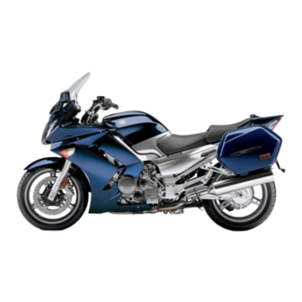
Summary of Contents for Yamaha FJR
- Page 1 OWNER’S MANUAL FJR1300AP 5P5-28199-E0...
- Page 2 EAU26943 DECLARATION of CONFORMITY Company: MORIC CO., LTD. Address: 1450-6 Mori Mori-Machi Shuchi-gun Shizuoka 437-0292 Japan Hereby declare that the product: Kind of equipment: IMMOBILIZER Type-designation: 5SL-00 is in compliance with following norm(s) or documents: R&TTE Directive(1999/5/EC) EN300 330-2 v1.1.1(2001-6), EN60950-1(2001) Two or Three-Wheel Motor Vehicles Directive(97/24/EC: Chapter 8, EMC) Place of issue: Shizuoka, Japan Date of issue: 1 Aug.
- Page 3 EAU10100 Welcome to the Yamaha world of motorcycling! As the owner of the FJR1300AP, you are benefiting from Yamaha’s vast experience and newest technology regarding the design and manufacture of high-quality products, which have earned Yamaha a reputation for dependability.
-
Page 4: Important Manual Information
This manual should be considered a permanent part of this motorcycle and should remain with it even if the motorcycle is subsequently sold. Yamaha continually seeks advancements in product design and quality. Therefore, while this manual contains the most current product information available at the time of printing, there may be minor discrepancies between your motorcycle and this manual. - Page 5 IMPORTANT MANUAL INFORMATION EAU10200 FJR1300AP OWNER’S MANUAL ©2006 by Yamaha Motor Co., Ltd. 1st edition, March 2006 All rights reserved. Any reprinting or unauthorized use without the written permission of Yamaha Motor Co., Ltd. is expressly prohibited. Printed in Japan.
-
Page 6: Table Of Contents
TABLE OF CONTENTS SAFETY INFORMATION ....1-1 Adjusting the headlight beams ..3-23 Checking the spark plugs ....6-7 Handlebar position ....... 3-24 Engine oil and oil filter cartridge ..6-8 DESCRIPTION ........2-1 Opening and closing the Final gear oil ........ 6-10 Left view ..........2-1 cowlings ........ - Page 7 TABLE OF CONTENTS Lubricating the swingarm pivots ...6-24 Lubricating the rear suspension ...6-24 Checking the front fork ....6-25 Checking the steering ....6-25 Checking the wheel bearings ..6-26 Battery ..........6-26 Replacing the fuses ......6-28 Headlight bulb ......6-29 Front turn signal light ....6-29 Replacing a rear turn signal light bulb or a tail/brake light bulb ..6-30 Replacing the license plate light...
-
Page 8: Safety Information
SAFETY INFORMATION EAU40950 AND/OR WHEN MADE NECES- • Ride where other motorists can SARY BY MECHANICAL CONDI- see you. Avoid riding in another MOTORCYCLES SINGLE TIONS. motorist’s blind spot. TRACK VEHICLES. THEIR SAFE USE Many accidents involve inexperi- AND OPERATION ARE DEPENDENT Safe riding enced operators. - Page 9 Modifications When loading within this weight limit, Modifications made to this motorcycle keep the following in mind: Protective apparel not approved by Yamaha, or the re- Cargo accessory weight The majority of fatalities from motor- moval of original equipment, may ren-...
- Page 10 If accessories lights or engine power. been specifically designed for use on are added to the handlebar or this motorcycle. Since Yamaha cannot front fork area, they must be as Gasoline and exhaust gas test all other accessories that may be...
- Page 11 SAFETY INFORMATION Never start the engine or let it run When transporting the motorcycle for any length of time in a closed in another vehicle, make sure that area. The exhaust fumes are poi- it is kept upright. If the motorcycle sonous and may cause loss of should lean over, gasoline may consciousness and death within a...
-
Page 12: Description
DESCRIPTION EAU10410 Left view 1. Accessory box (page 3-23) 9. Air filter element (page 6-13) 2. Front fork spring preload adjusting bolt (page 3-25) 10.Shift pedal (page 3-15) 3. Front fork rebound damping force adjusting knob (page 3-25) 11.Engine oil filler cap (page 6-8) 4. -
Page 13: Right View
DESCRIPTION EAU10420 Right view 1. Storage compartment (page 3-22) 9. Shock absorber assembly rebound damping force adjusting knob (page 3-27) 2. Fuel tank cap (page 3-17) 10.Rear brake fluid reservoir (page 6-20) 3. Fuse box (page 6-28) 4. Windshield (page 3-13) 5. -
Page 14: Controls And Instruments
DESCRIPTION EAU10430 Controls and instruments 1. Rear view mirror (page 3-25) 9. Right handlebar switches (page 3-13) 2. Clutch lever (page 3-15) 10.Brake lever (page 3-16) 3. Left handlebar switches (page 3-13) 11.Throttle grip (page 6-15) 4. Clutch fluid reservoir (page 6-20) 12.Main switch/steering lock (page 3-2) 5. -
Page 15: Instrument And Control Functions
Do not expose any key to exces- a Yamaha dealer to have them re-reg- sively high temperatures. istered. Do not use the key with the red Do not place any key close to bow for driving. -
Page 16: Main Switch/Steering Lock
INSTRUMENT AND CONTROL FUNCTIONS EAU10471 EAU26811 To lock the steering Main switch/steering lock All electrical circuits are supplied with power; the meter lighting, taillights, li- cense plate light and auxiliary lights come on, and the engine can be start- ed. The key cannot be removed. NOTE: The headlights come on automatically when the engine is started and stay on... -
Page 17: Indicator And Warning Lights
INSTRUMENT AND CONTROL FUNCTIONS To unlock the steering EAU39460 EAU11003 (Parking) Indicator and warning lights The steering is locked, and the tail- lights, license plate light and auxiliary lights are on. The hazard lights and turn signal lights can be turned on, but all other electrical systems are off. - Page 18 When this occurs, The electrical circuit of the warning light EAU11080 have a Yamaha dealer check the self- High beam indicator light “ ” can be checked by turning the key to diagnosis system.
-
Page 19: Speedometer
INSTRUMENT AND CONTROL FUNCTIONS mobilizer system is enabled. After 24 EAU11601 EAU11872 Speedometer Tachometer hours have passed, the indicator light will stop flashing, however the immobi- lizer system is still enabled. This model is also equipped with a self- diagnosis device for the immobilizer system. -
Page 20: Multi-Function Display
INSTRUMENT AND CONTROL FUNCTIONS EAU26867 a fuel reserve tripmeter (which Odometer and tripmeter modes Multi-function display shows the distance traveled on the fuel reserve) a clock a fuel meter a coolant temperature meter a transmission gear display an ambient temperature display a fuel consumption display (instan- taneous and average consumption functions) - Page 21 INSTRUMENT AND CONTROL FUNCTIONS distance traveled from that point. In that Clock Fuel meter case, pushing the “SELECT” button switches the display between the vari- ous tripmeter and odometer modes in the following order: F-TRIP → TRIP 1 → TRIP 2 → ODO → F-TRIP To reset a tripmeter, select it by push- ing the “SELECT”...
- Page 22 INSTRUMENT AND CONTROL FUNCTIONS will start flashing. If this occurs, have a ECA10020 Ambient temperature, instanta- CAUTION: Yamaha dealer check the electrical cir- neous fuel consumption and aver- cuit. fuel consumption modes Do not operate the engine if it is (except for the UK) overheated.
- Page 23 INSTRUMENT AND CONTROL FUNCTIONS Ambient temperature mode The accuracy of the temperature When the display is set to “L/100 reading may be affected when km”, the amount of fuel necessary riding slowly (approximately under to travel 100 km under the current 20 km/h) or when stopped at traffic riding conditions is shown.
- Page 24 “AV _ _._ km/L” or “AV _ _._ L/100 km”. If there is a malfunction, “– –.–” will When the average fuel consumption be displayed. Have a Yamaha dealer mode is selected, the display flashes check the vehicle. for five seconds, and then, depending on the unit set, “AV _ _._ km/L”...
- Page 25 1 km (0.6 mi). Instantaneous fuel consumption mode ECA15472 CAUTION: If there is a malfunction, “– –.–” will be displayed. Have a Yamaha dealer check the vehicle. 1. Average fuel consumption Self-diagnosis device This display shows the average fuel consumption since it was last reset.
- Page 26 If the multi-function display indicates er- two-digit error code (e.g., 11, 12, 13). and then have a Yamaha dealer check ror code 52, this could be caused by If the multi-function display indicates the vehicle.
-
Page 27: Anti-Theft Alarm (Optional)
EAU12345 Right Anti-theft alarm (optional) Handlebar switches This model can be equipped with an Left optional anti-theft alarm by a Yamaha dealer. Contact a Yamaha dealer for more information. 1. Engine stop switch “ ” 2. Hazard switch “ ”... - Page 28 INSTRUMENT AND CONTROL FUNCTIONS position. To cancel the turn signal EAU12500 The hazard lights are used in case of Horn switch “ ” lights, push the switch in after it has re- an emergency or to warn other drivers Press this switch to sound the horn. turned to the center position.
-
Page 29: Clutch Lever
INSTRUMENT AND CONTROL FUNCTIONS EAU12830 Make sure that the appropriate setting EAU12870 Clutch lever Shift pedal on the adjusting dial is aligned with the arrow mark on the clutch lever. The clutch lever is equipped with a clutch switch, which is part of the igni- tion circuit cut-off system. -
Page 30: Brake Lever
EAU39530 Brake lever Brake pedal The brake lever is located at the right The Yamaha ABS (Anti-lock Brake handlebar grip. To apply the front System) features a dual electronic con- brake, pull the lever toward the handle- trol system, which acts on the front and bar grip. -
Page 31: Fuel Tank Cap
However, special tools are not properly closed and locked. required, so please consult your Yamaha dealer when performing EWA11090 WARNING this test. Make sure that the fuel tank cap is properly closed before riding. -
Page 32: Fuel
Avoid spilling fuel on the hot en- Your Yamaha engine has been de- gine. signed to use regular unleaded gaso- line with a research octane number of 91 or higher. -
Page 33: Fuel Tank Breather/Overflow Hose
INSTRUMENT AND CONTROL FUNCTIONS EAU39450 EAU13441 EAU40960 Fuel tank breather/overflow Catalytic converter Seat hose This vehicle is equipped with catalytic converters in the exhaust system. To remove the seat Push the seat lock lever, located under EWA10860 WARNING the back of the seat, to the left as shown, and then pull the seat off. -
Page 34: Adjusting The Seat Height
INSTRUMENT AND CONTROL FUNCTIONS EAU40970 Adjusting the seat height The seat height can be adjusted to one of two positions to suit the rider’s pref- erence. The seat height was adjusted to the lower position at delivery. 1. Projection 1. Seat height position adjuster 2. - Page 35 INSTRUMENT AND CONTROL FUNCTIONS 6. Align the projection on the bottom of the seat with the “H” position slot, and then push the rear of the seat down to lock it in place as shown. 1. Seat height position adjuster 1.
-
Page 36: Storage Compartment
INSTRUMENT AND CONTROL FUNCTIONS 6. Align the projection on the bottom EAU14451 When washing the vehicle, be careful Storage compartment of the seat with the “L” position not to let any water enter the storage slot, and then push the rear of the compartment. -
Page 37: Accessory Box
INSTRUMENT AND CONTROL FUNCTIONS EAU39480 ECA11800 EAU39610 Accessory box Adjusting the headlight CAUTION: The accessory box is located beside beams Do not place heat-sensitive items in the meter panel. The headlight adjusting knobs are used the accessory box. The accessory to raise or lower the height of the head- box gets extremely hot especially To open the accessory box... -
Page 38: Handlebar Position
The handlebars can be adjusted to one ings of three positions to suit the rider’s pref- The cowlings can be tilted back 30 mm erence. Have a Yamaha dealer adjust (1.18 in) for added ventilation to suit the the position of the handlebars. riding conditions. -
Page 39: Rear View Mirrors
INSTRUMENT AND CONTROL FUNCTIONS EAU39671 EAU14731 Rear view mirrors Adjusting the front fork The rear view mirrors of this vehicle can This front fork is equipped with spring be folded forward or backward for park- preload adjusting bolts, rebound damp- ing in narrow spaces. - Page 40 INSTRUMENT AND CONTROL FUNCTIONS load thereby soften Rebound damping force Compression damping force suspension, turn the adjusting bolt on each fork leg in direction (b). NOTE: Align the appropriate groove on the ad- justing mechanism with the top of the front fork cap bolt.
-
Page 41: Adjusting The Shock Absorber Assembly
INSTRUMENT AND CONTROL FUNCTIONS ECA10100 EAU40980 load thereby harden Adjusting the shock absorber CAUTION: suspension, move the spring preload assembly adjusting lever in direction (a). Never attempt to turn an adjusting This shock absorber assembly is mechanism beyond the maximum or equipped with a spring preload adjust- Rebound damping force minimum settings. -
Page 42: Grip Warmer Adjusting Knob
Standard: formance. the engine is running. 12 click(s) in direction (b)* Always have a Yamaha dealer Maximum (hard): Use the grip warmer adjusting knob, lo- service the shock absorber. 3 click(s) in direction (b)*... -
Page 43: Sidestand
INSTRUMENT AND CONTROL FUNCTIONS EAU15301 below and have a Yamaha dealer re- NOTE: Sidestand pair it if it does not function proper- When the vehicle is stopped or travel- The sidestand is located on the left side ing at extremely low speeds (e.g., in of the frame. -
Page 44: Ignition Circuit Cut-Off System
Periodically check the operation of the ignition circuit cut-off system according to the following procedure. EWA10260 WARNING The vehicle must be placed on the centerstand during this in- spection. If a malfunction is noted, have a Yamaha dealer check the sys- tem before riding. 3-30... - Page 45 5. Push the start switch. Does the engine start? The neutral switch may be defective. The motorcycle should not be ridden until checked by a Yamaha dealer. With the engine still running: 6. Move the sidestand up. 7. Keep the clutch lever pulled.
-
Page 46: Auxiliary Dc Jack
INSTRUMENT AND CONTROL FUNCTIONS EAU39651 EWA14360 Auxiliary DC jack WARNING This vehicle is equipped with an auxilia- To prevent electrical shock or short- ry DC jack in the accessory box. circuiting, make sure that the cap is A 12-V accessory connected to the installed when the auxiliary DC jack auxiliary jack can be used when the key is not being used. -
Page 47: Pre-Operation Checks
PRE-OPERATION CHECKS EAU15591 The condition of a vehicle is the owner’s responsibility. Vital components can start to deteriorate quickly and unexpectedly, even if the vehicle remains unused (for example, as a result of exposure to the elements). Any damage, fluid leakage or loss of tire air pressure could have serious consequences. -
Page 48: Pre-Operation Check List
• If necessary, add recommended coolant to specified level. 6-12 • Check cooling system for leakage. • Check operation. • If soft or spongy, have Yamaha dealer bleed hydraulic system. • Check brake pads for wear. Front brake • Replace if necessary. - Page 49 • Make sure that operation is smooth. • Check cable free play. Throttle grip 6-15, 6-22 • If necessary, have Yamaha dealer adjust cable free play and lubricate cable and grip housing. • Make sure that operation is smooth. Control cables 6-22 •...
-
Page 50: Operation And Important Riding Points
Exhaust fumes check the function of the igni- should be on, otherwise have a are poisonous, and inhaling tion circuit cut-off system ac- Yamaha dealer check the electrical cir- them can cause loss of con- cording procedure cuit. -
Page 51: Shifting
OPERATION AND IMPORTANT RIDING POINTS ECA11040 EAU16671 ECA10260 Shifting CAUTION: CAUTION: For maximum engine life, never ac- Even with the transmission in celerate hard when the engine is the neutral position, do not cold! coast for long periods of time with the engine off, and do not NOTE: tow the motorcycle for long dis-... -
Page 52: Tips For Reducing Fuel Consumption
If any engine trouble should oc- result in engine overheating must be lights or at railroad crossings). cur during the engine break-in avoided. period, immediately have a Yamaha dealer check the vehi- EAU17121 cle. 0–1000 km (0–600 mi) Avoid prolonged operation above 4500 r/min. -
Page 53: Parking
OPERATION AND IMPORTANT RIDING POINTS EAU17212 Parking When parking, stop the engine, and then remove the key from the main switch. EWA10310 WARNING Since the engine and exhaust system can become very hot, park in a place where pedestri- ans or children are not likely to touch them. -
Page 54: Periodic Maintenance And Minor Repair
If you are not familiar with mainte- certain maintenance work correctly. nance work, have a Yamaha dealer do it for you. NOTE: If you do not have the tools or experi- ence required for a particular job, have a Yamaha dealer perform it for you. -
Page 55: Periodic Maintenance And Lubrication Chart
The annual checks must be performed every year, except if a kilometer-based maintenance is performed in- stead. From 50000 km, repeat the maintenance intervals starting from 10000 km. Items marked with an asterisk should be performed by a Yamaha dealer as they require special tools, data and technical skills. ODOMETER READING (× 1000 km) - Page 56 PERIODIC MAINTENANCE AND MINOR REPAIR ODOMETER READING (× 1000 km) ANNUAL ITEM CHECK OR MAINTENANCE JOB CHECK √ √ √ √ 9 * Wheels • Check runout and for damage. • Check tread depth and for damage. • Replace if necessary. √...
- Page 57 PERIODIC MAINTENANCE AND MINOR REPAIR ODOMETER READING (× 1000 km) ANNUAL ITEM CHECK OR MAINTENANCE JOB CHECK √ √ √ √ √ • Check coolant level and vehicle for coolant leakage. 23 * Cooling system • Change. Every 3 years •...
-
Page 58: Removing And Installing Panels
PERIODIC MAINTENANCE AND MINOR REPAIR EAU18771 Removing and installing pan- The panels shown need to be removed to perform some of the maintenance jobs described in this chapter. Refer to this section each time a panel needs to be removed and installed. 1. - Page 59 PERIODIC MAINTENANCE AND MINOR REPAIR EAU41120 Panel C To remove the panel 1. Remove the seat. (See page 3-19.) 2. Remove the bolt and the quick fas- tener screws, and then take the panel off. 1. Panel B 2. Install the seat. 2.
-
Page 60: Checking The Spark Plugs
Do not attempt to diagnose 0.7–0.8 mm (0.028–0.031 in) such problems yourself. Instead, have a Yamaha dealer check the vehicle. Clean the surface of the spark plug If a spark plug shows signs of electrode gasket and its mating surface, and then... -
Page 61: Engine Oil And Oil Filter Cartridge
PERIODIC MAINTENANCE AND MINOR REPAIR EAU19881 2. Place an oil pan under the engine Engine oil and oil filter car- NOTE: to collect the used oil. The engine oil should be between the tridge 3. Remove the engine oil filler cap minimum and maximum level marks. - Page 62 An oil filter wrench is available at a seated. 43 Nm (4.3 m·kgf, 31 ft·lbf) Yamaha dealer. 6. Install the new oil filter cartridge, 8. Add the specified amount of the 5. Apply a thin coat of engine oil to...
-
Page 63: Final Gear Oil
If any page (since the engine oil also or remains on, immediately turn the leakage is found, have a Yamaha deal- lubricates the clutch), do not engine off and have a Yamaha dealer er check and repair the vehicle. In addi- mix any chemical additives. - Page 64 PERIODIC MAINTENANCE AND MINOR REPAIR 2. Remove the oil filler bolt, and then Tightening torque: Tightening torque: check the oil level in the final gear Final gear oil filler bolt: Final gear oil filler bolt: case. 23 Nm (2.3 m·kgf, 17 ft·lbf) 23 Nm (2.3 m·kgf, 17 ft·lbf) NOTE: 6.
-
Page 65: Coolant
PERIODIC MAINTENANCE AND MINOR REPAIR EAU20070 Coolant NOTE: The coolant should be between the The coolant level should be checked minimum and maximum level marks. before each ride. In addition, the cool- ant must be changed at the intervals specified in the periodic maintenance and lubrication chart. -
Page 66: Cleaning The Air Filter Element
If water has been added to the cap when the engine is hot. Clean the air filter element more fre- coolant, have a Yamaha dealer quently if you are riding in unusually The coolant must be changed at the in- check the antifreeze content of wet or dusty areas. - Page 67 PERIODIC MAINTENANCE AND MINOR REPAIR out with compressed air as shown. ECA15410 CAUTION: If the air filter element is damaged, replace it. Make sure that the fuel tank breath- er/overflow hose is not pinched. 1. Air filter case cover 2. Screw 4.
-
Page 68: Checking The Engine Idling Speed
To prevent this checked as follows and, if necessary, from occurring, the valve clearance adjusted by a Yamaha dealer at the in- must be adjusted by a Yamaha dealer tervals specified in the periodic mainte- at the intervals specified in the periodic nance and lubrication chart. -
Page 69: Tires
PERIODIC MAINTENANCE AND MINOR REPAIR EAU21500 damage, loss of control, or se- Tire air pressure (measured on cold Tires vere injury. Make sure that the tires): To maximize the performance, durabil- total weight of rider, cargo, and 0–90 kg (0–198 lb): ity, and safe operation of your motor- Front: accessories does not exceed... - Page 70 Tire information glass fragments in it, or if the sidewall is Use only the tire valves and cracked, have a Yamaha dealer re- valve cores listed below to place the tire immediately. avoid tire deflation during a high-speed ride.
-
Page 71: Cast Wheels
Always adjust the tire air pres- 180/55 ZR17M/C (73W) fore each ride. If any damage is Manufacturer/model: sure according to the operating found, have a Yamaha dealer re- METZELER/Roadtec Z6C conditions. BRIDGESTONE/BT020R place the wheel. Do not attempt FRONT and REAR:... -
Page 72: Clutch Lever
If lubrication chart. leakage before each ride. If the clutch necessary, have a Yamaha dealer ad- lever free play does become excessive, just the brake light switch. EAU22420... -
Page 73: Checking The Brake And Clutch Fluid Levels
PERIODIC MAINTENANCE AND MINOR REPAIR indicator groove has almost disap- EAU22680 Clutch Checking the brake and clutch peared, have a Yamaha dealer replace fluid levels the brake pads as a set. Front brake EAU22500 Rear brake pads 1. Minimum level mark... -
Page 74: Changing The Brake And Clutch Fluids
Have a Yamaha dealer change the Use only the recommended quality Brake fluid may deteriorate paint- brake and clutch fluids at the intervals brake fluid, otherwise the rubber ed surfaces or plastic parts. -
Page 75: Checking And Lubricating The Cables
If a cable is damaged maintenance chart. or does not move smoothly, have a Yamaha dealer check or replace it. Recommended lubricant: Engine oil EWA10720 WARNING... -
Page 76: Checking And Lubricating The Brake And Clutch Levers
PERIODIC MAINTENANCE AND MINOR REPAIR EAU23140 Recommended lubricant: Recommended lubricant: Checking and lubricating the Lithium-soap-based grease (all-pur- Lithium-soap-based grease (all-pur- brake and clutch levers pose grease) pose grease) Brake lever Clutch lever The operation of the brake and clutch levers should be checked before each ride, and the lever pivots should be lu- bricated if necessary. -
Page 77: Checking And Lubricating The Centerstand And Sidestand
Lithium-soap-based grease Recommended lubricant: EWA10740 WARNING Lithium-soap-based grease If the centerstand or sidestand does not move up and down smoothly, have a Yamaha dealer check or re- pair it. Recommended lubricant: Lithium-soap-based grease (all-pur- pose grease) 6-24... -
Page 78: Checking The Front Fork
Securely support the vehicle so that fork does not operate smoothly, damage and excessive oil leakage. there is no danger of it falling over. have a Yamaha dealer check or re- pair it. To check the operation 2. Hold the lower ends of the front 1. -
Page 79: Checking The Wheel Bearings
There is no need to check the electrolyte or to add distilled water. To charge the battery Have a Yamaha dealer charge the bat- tery as soon as possible if it seems to have discharged. Keep in mind that the 6-26... - Page 80 IES OUT OF THE REACH OF If you do not have access to a electrical accessories. CHILDREN. sealed-type (MF) battery charg- have a Yamaha dealer EWA10760 WARNING charge your battery. To store the battery Electrolyte is poisonous and 1.
-
Page 81: Replacing The Fuses
PERIODIC MAINTENANCE AND MINOR REPAIR EAU23657 Specified fuses: Replacing the fuses Main fuse: The main fuse, the fuse boxes and the 50.0 A ABS motor fuse are located under pan- Headlight fuse: el A. (See page 6-5.) 25.0 A Signaling system fuse: 15.0 A Ignition fuse: 10.0 A... -
Page 82: Headlight Bulb
If a front turn signal light does not come check if the device operates. Yamaha dealer check its electrical cir- on, have a Yamaha dealer check its 4. If the fuse immediately blows cuit or replace the bulb. electrical circuit or replace the bulb. -
Page 83: Replacing A Rear Turn Signal Light Bulb Or A Tail/Brake Light Bulb
PERIODIC MAINTENANCE AND MINOR REPAIR EAU40990 EAU24310 3. Remove the defective bulb by pull- Replacing a rear turn signal Replacing the license plate ing it out. light bulb or a tail/brake light light bulb 4. Insert a new bulb into the socket. bulb 1. -
Page 84: Auxiliary Light Bulb
The following troubleshooting charts represent quick and easy procedures for checking these vital systems your- self. However, should your motorcycle require any repair, take it to a Yamaha dealer, whose skilled technicians have the necessary tools, experience, and know-how to service the motorcycle properly. -
Page 85: Troubleshooting Charts
Remove the spark plugs and check the electrodes. The engine does not start. Have a Yamaha dealer check the vehicle. Check the battery. 4. Battery The engine turns over The battery is good. - Page 86 Start the engine. If the engine overheats again, have a The coolant level Yamaha dealer check and repair the cooling system. is OK. NOTE: If coolant is not available, tap water can be temporarily used instead, provided that it is changed to the recommended coolant as soon as possible.
-
Page 87: Motorcycle Care And Storage
MOTORCYCLE CARE AND STORAGE EAU26060 ucts onto seals, gaskets and wheel thinner, fuel (gasoline), rust re- Care axles. Always rinse the dirt and de- movers or inhibitors, brake flu- While the open design of a motorcycle greaser off with water. id, antifreeze or electrolyte. - Page 88 MOTORCYCLE CARE AND STORAGE After normal use ECA10790 5. Touch up minor paint damage CAUTION: Remove dirt with warm water, a mild caused by stones, etc. detergent, and a soft, clean sponge, 6. Wax all painted surfaces. Do not use warm water since it in- and then rinse thoroughly with clean 7.
-
Page 89: Storage
Always store your motorcycle in a cool, NOTE: and spark plugs. dry place and, if necessary, protect it Consult a Yamaha dealer for advice on b. Pour a teaspoonful of engine oil against dust with a porous cover. what products to use. - Page 90 MOTORCYCLE CARE AND STORAGE 4. Lubricate all control cables and the pivoting points of all levers and pedals as well as of the side- stand/centerstand. 5. Check and, if necessary, correct the tire air pressure, and then lift the motorcycle so that both of its wheels are off the ground.
-
Page 91: Specifications
SPECIFICATIONS Dimensions: Engine oil: Fuel injector: Overall length: Type: Manufacturer: 2230 mm (87.8 in) SAE20W40 NIPPON INJECTOR Overall width: Recommended engine oil grade: Model/quantity: 750 mm (29.5 in) API service SE, SF, SG type or higher INP-151/4 Overall height: Engine oil quantity: Spark plug (s): 1450 mm (57.1 in) Without oil filter cartridge replacement:... - Page 92 SPECIFICATIONS 3rd: (Total weight of rider, cargo and Operation: 31/23 (1.348) accessories) Right hand operation 4th: Tire air pressure (measured on cold Recommended fluid: 28/26 (1.077) DOT 4 tires): 5th: Rear brake: Loading condition: 26/28 (0.929) Type: 0–90 kg (0–198 lb) Chassis: Single disc brake Front:...
- Page 93 SPECIFICATIONS Voltage, capacity: Fuses: 12 V, 12.0 Ah Main fuse: Headlight: 50.0 A Bulb type: Headlight fuse: Halogen bulb 25.0 A Bulb voltage, wattage × quantity: Signaling system fuse: 15.0 A Headlight: 12 V, 60 W/55.0 W × 2 Ignition fuse: 10.0 A Tail/brake light: 12 V, 5.0 W/21.0 W ×...
-
Page 94: Consumer Information
Record the key identification number, vehicle identification number and mod- el label information in the spaces pro- vided below for assistance when ordering spare parts from a Yamaha dealer or for reference in case the vehi- cle is stolen. KEY IDENTIFICATION NUMBER: 1. - Page 95 EAU26460 Model label 1. Model label The model label is affixed to the loca- tion shown. Record the information on this label in the space provided. This in- formation will be needed when ordering spare parts from a Yamaha dealer.
- Page 96 INDEX Engine stop switch........ 3-14 Engine trouble warning light ....3-4 ABS............3-16 Main switch/steering lock ......3-2 ABS warning light........3-4 Model label..........9-2 Accessory box........3-23 Final gear oil ......... 6-10 Multi-function display.......3-6 Air filter element, cleaning..... 6-13 Front and rear brake pads, checking..6-19 Anti-theft alarm (optional)......
- Page 97 INDEX Storage ........... 7-3 Storage compartment ......3-22 Swingarm pivots, lubricating....6-24 Tachometer ..........3-5 Throttle cable free play, checking..6-15 Throttle grip and cable, checking and lubricating..... 6-22 Tires............6-16 Tool kit ............ 6-1 Troubleshooting........6-31 Troubleshooting charts ......6-32 Turn signal indicator lights ......
- Page 100 YAMAHA MOTOR CO., LTD. PRINTED ON RECYCLED PAPER PRINTED IN JAPAN 2006.06-0.3×1 CR...
Need help?
Do you have a question about the FJR and is the answer not in the manual?
Questions and answers