
Related Manuals for Yamaha U-MAX G23A


Summary of Contents for Yamaha U-MAX G23A
- Page 1 READ THIS MANUAL CAREFULLY! It contains important safety information. OWNER’S/OPERATOR’S MANUAL G23A JU5-F8199-10 LIT-19626-01-17...
- Page 3 A thorough understand- ing of these simple instructions will help you to obtain maximum enjoyment from your new Yamaha. If you have any questions about the operation or maintenance of your utility vehicle, please con- sult a Yamaha dealer.
-
Page 4: Important Manual Information
NOTE: NOTE: Yamaha continually seeks advancements in product design and quality; therefore, while this manual contains the most current product information available at the time of printing, there may be minor discrepancies between your utility vehicle and this manual. If you have any questions concerning this manual, please consult your Yamaha dealer. - Page 5 YAMAHA GOLF-CAR COMPANY MAKES NO OTHER new Utility Vehicle purchased from an authorized Acts of God (i.e. lightning, hail damage, flooding, WARRANTY OF ANY KIND, EXPRESSED OR Yamaha dealer in the United States, will be free from fire, etc.) IMPLIED. IMPLIED...
- Page 6 You are responsible for presenting your specialty Air Induction System to meet stringent anti-smog standards. Yamaha must vehicle engine to a Yamaha dealer as soon as a Controlled hot air intake system warrant the emission control system on your speciality problem exists.
- Page 7 This work, modification, misuse, alteration, or improper work must be done at an authorized Yamaha dealer. maintenance (see your Owner’s/Operator’s Manual). Give notice to an authorized Yamaha dealer of any...
-
Page 8: Table Of Contents
Auxiliary DC jack......4-6 CONTENTS Cargo bed ........4-8 Trailer hitch bracket .......4-12 LOCATION OF THE WARNING AND SPECIFICATION LABELS..1-1 PRE-OPERATION CHECKS ....5-1 Pre-operation check list ....5-2 DESCRIPTION AND VEHICLE Brakes..........5-3 IDENTIFICATION ......2-1 Fuel ..........5-4 Features .......... 2-1 Engine oil .........5-5 Utility vehicle serial number..... - Page 9 DRIVING YOUR VEHICLE....7-1 Battery ........... 8-14 Getting to know your vehicle... 7-1 Fuse replacement......8-15 Learning to operate your vehicle ..7-3 Transmission oil......8-16 Turning your vehicle......7-3 Wheel removal....... 8-17 Braking ..........7-3 Wheel installation ......8-18 Going uphill ........
-
Page 10: Location Of The Warning And Specification Labels
L OCATION OF THE WARNING AND SPECIFICATION LABELS... - Page 11 They contain important information for safe and proper operation of your vehicle. Never remove any labels from your vehicle. If a la- bel becomes difficult to read or comes off, a re- placement label is available from your Yamaha dealer. WARNING WARNING...
- Page 12 Tighten cap before putting fuel container in cargo bed. When loading with cargo or towing a trailer: Reduce speed and allow more room to stop. Avoid hills and rough terrain. YAMAHA JU7-K7767-00 Be sure cargo is secured - a loose load could change handling unexpectedly.
-
Page 13: Description And Vehicle Identification
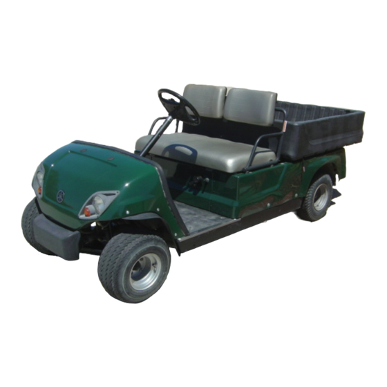
D ESCRIPTION AND VEHICLE IDENTIFICATION FEATURES 1. Steering wheel 2. Seat 3. Battery 4. Taillight 5. Rear tire 6. Fuel tank 7. Starter (choke) 8. Drive select lever 9. Front tire 10. Headlight 11. Accelerator pedal 12. Brake pedal 13. Parking brake pedal 14. -
Page 14: Utility Vehicle Serial Number
The first three digits of the serial number are for model identification; the remaining digits are the unit production number. Keep a record of these numbers for reference when ordering parts from a Yamaha dealer. 1. Key identification number... -
Page 15: Safety Information
SAFETY INFORMATION SEVERE INJURY OR DEATH can result if Never operate at speeds too fast for your you do not follow these instructions: skills or the conditions. Always go at a Read this manual and all labels carefully speed that is proper for the terrain, visibility, and follow the operating procedures de- and operating conditions, and your experi- scribed. - Page 16 Always go slowly and be extra careful when Always check for obstacles before operat- operating on unfamiliar terrain. Always be ing in a new area. alert to changing terrain conditions when Always be sure there are no obstacles or driving the vehicle. people behind you when you operate in re- Never operate on rough, slippery, or loose verse.
-
Page 17: Control Functions
CONTROL FUNCTIONS All electrical circuits (except for the headlights Main switch and taillights) are switched on. The utility vehicle can be operated. All electrical circuits are switched on. The headlights and taillights come on. The utility vehicle can be operated. The main switch positions are as follows: OFF: All electrical circuits are switched off. -
Page 18: Oil Level Warning Light
Oil level warning light Fuel tank cap This warning light comes on when the engine Remove the fuel tank cap by turning it coun- oil level is low. If the light comes on, stop terclockwise. the engine, check the engine oil level, and add oil as necessary. -
Page 19: Drive Select Lever
Drive select lever NOTE: The back-up buzzer will sound when the drive The drive select lever is used for driving the select lever is shifted to “R.” utility vehicle either forward or in reverse. After coming to a complete stop, shift the lever to the desired position. -
Page 20: Accelerator Pedal
Accelerator pedal Brake pedal The accelerator pedal controls the utility vehi- Press the brake pedal down to slow or stop cle’s speed. the utility vehicle. Action Vehicle speed Depress pedal Increase Release pedal Decrease 1. Brake pedal NOTE: The engine stops when the accelerator pedal is released and the utility vehicle comes to a complete stop. -
Page 21: Parking Brake Pedal
Parking brake pedal Starter (choke) Press the parking brake pedal down whenev- Pull the starter (choke) knob out and hold it er parking the utility vehicle. when starting a cold engine. Release it after the engine starts. 1. Parking brake pedal 1. -
Page 22: Horn Button
Horn button Auxiliary DC jack Step on the horn button to sound the horn. The auxiliary DC jack is located in the front panel. The auxiliary DC jack can be used for acces- sories such as lights, radios, etc. The auxiliary DC jack should only be used for short periods if the utility vehicle is not being operated. - Page 23 1. Set the main switch to “ON”. CAUTION: 2. Open the auxiliary DC jack cap, and then Do not use accessories requiring insert the accessory power plug into the more than the maximum rated capaci- jack. ty for the auxiliary DC jack. This may overload the circuit and cause the fuse to blow.
-
Page 24: Cargo Bed
Cargo bed Opening and closing the tailgate 1. Cargo bed 1. Tailgate 2. Latch (× 2) To open: Unhook the latches, and then lower the tail- gate. To close: Place the tailgate in its original position, and then hook the latches. - Page 25 Lifting and lowering the cargo bed To lift: Pull the cargo bed release lever towards the rear, and then slowly lift up the cargo bed until end of the prop rod hooks onto the prop rod guide to support the cargo bed. To lower: Slightly lift up the cargo bed, unhook the end of the prop rod, and then lower the cargo bed...
- Page 26 WARNING WARNING POTENTIAL HAZARD POTENTIAL HAZARD Overloading the cargo bed. Carrying a passenger in the cargo bed. WHAT CAN HAPPEN WHAT CAN HAPPEN Could cause changes in vehicle han- The passenger could fall, be thrown out, dling which could lead to an accident. or be struck by objects in the cargo bed.
- Page 27 WARNING WARNING POTENTIAL HAZARD POTENTIAL HAZARD Pinch point. Fire or explosion while filling a portable fuel container. WHAT CAN HAPPEN You or someone else could be pinched WHAT CAN HAPPEN between the cargo bed and the frame or Static electricity sparks can ignite fuel the seat backs when the bed is being vapors.
-
Page 28: Trailer Hitch Bracket
Trailer hitch bracket This vehicle is equipped with a 5 cm (2 in) re- ceiver bracket for a standard trailer hitch. Trailer towing equipment can be obtained at a Yamaha dealer. (See page 6-5 for precaution information.) 1. Trailer hitch bracket 4-12... -
Page 29: Pre-Operation Checks
P RE-OPERATION CHECKS Pre-operation checks should be made each WARNING time you use your utility vehicle. Get in the POTENTIAL HAZARD habit of performing the following checks in the Failure to inspect the vehicle before op- same way so that they become second na- erating. -
Page 30: Pre-Operation Check List
Pre-operation check list Before using this vehicle, check the following points: ITEM ROUTINE PAGE Brakes • Check for proper operation, condition and free play. 5-3, 8-19–8-21 Parking brake • Check for proper operation, condition and free play. 5-3, 8-19–8-21 • Check fuel level. Fuel 5-4–5-5 •... -
Page 31: Brakes
HOW TO AVOID THE HAZARD firm feeling when the brakes are applied. If Always check the brakes at the start of not, have the vehicle inspected by a Yamaha every ride. Do not operate the vehicle if dealer. you find any problem with the brakes. If... -
Page 32: Fuel
10%. Gaso- and piston rings, as well as to the exhaust hol containing methanol is not recommended system. by Yamaha because it may cause fuel system damage or vehicle performance problems. -
Page 33: Engine Oil
Engine oil WARNING Make sure that the engine oil is at the speci- POTENTIAL HAZARD fied level. Add oil if necessary. (See pages Improper care when refueling. 8-8–8-9 for details.) WHAT CAN HAPPEN CAUTION: Fuel can spill, which can cause a fire and severe injury. -
Page 34: Accelerator Pedal
POTENTIAL HAZARD and fasteners before a ride. Take the utility Checking operation of the accelerator vehicle to a Yamaha dealer or refer to the Ser- pedal with the key in the main switch. vice Manual for the correct tightening torques. -
Page 35: Tires
HOW TO AVOID THE HAZARD 1. The tires listed below have been ap- proved by Yamaha Motor Manufac- turing Corporation of America for this model. Other tire combinations NOTE: Measure the tire pressure twice and use the are not recommended. - Page 36 Tire wear limit 2. The tires should be set to the rec- When the tire groove decreases to 1 mm ommended pressure: (0.04 in) due to wear, replace the tire. Recommended tire pressure Front 150 kPa (1.53 kgf/cm , 21 psi) Rear 207 kPa (2.11 kgf/cm , 30 psi) Check and adjust tire pressures when...
-
Page 37: Operation
O PERATION 2. Turn the main switch to “ON” or “ON ”. Starting a cold engine 1. With the parking brake applied, shift the drive select lever to “F” for forward, or “R” for reverse. WARNING POTENTIAL HAZARD Depressing accelerator pedal while turning on the main switch. - Page 38 3. Pull the starter (choke) knob out and hold 4. Check that your path is clear in the direc- it while starting a cold engine. Release tion you plan to go, and slowly depress the starter (choke) knob after the engine the accelerator pedal.
-
Page 39: Starting A Warm Engine
Starting a warm engine Stopping To start a warm engine, refer to the “Starting a To stop the utility vehicle, gradually press cold engine” section. The starter (choke) down on the brake pedal. should not be used. When the utility vehicle has come to a stop, apply the parking brake pedal and turn the main switch to “OFF.”... -
Page 40: Accessories And Loading
Choose only accessories designed for your cle. Examples include (but are not limited vehicle. Your Yamaha dealer has a variety to) an object that limits your ability to turn of genuine Yamaha accessories. Other ac-... - Page 41 Tow weight (Including driver, ries. All parts and accessories added to passenger, vehicle cargo and trailer this vehicle should be genuine Yamaha and trailer cargo): or equivalent components designed for 590 kg (1300 lb)
- Page 42 Do not exceed the maximum tongue Make sure the load does not interfere with weight. You can measure tongue weight controls or your ability to see where you are with a bathroom scale. Put the tongue of going. the loaded trailer on the scale with the Drive more slowly than you would without a tongue at hitch height.
- Page 43 WARNING POTENTIAL HAZARD Overloading this vehicle or carrying or towing cargo improperly. WHAT CAN HAPPEN Could cause changes in vehicle han- dling which could lead to an accident. HOW TO AVOID THE HAZARD Never exceed the stated load capacity for this vehicle. Cargo should be properly distributed and securely attached.
-
Page 44: Driving Your Vehicle
D RIVING YOUR VEHICLE WARNING POTENTIAL HAZARD GETTING TO KNOW YOUR VEHICLE Carrying a passenger in the cargo bed. This off-highway utility vehicle will handle and maneuver differently from an ordinary pas- WHAT CAN HAPPEN senger car or other vehicle. The passenger could fall or be struck by objects in the cargo bed. - Page 45 Carrying a passenger and cargo can affect WARNING vehicle handling. POTENTIAL HAZARD The total weight of operator, passenger, ac- Overloading this vehicle or carrying or cessories, cargo, trailer tongue weight, and towing cargo improperly. the trailer must not exceed the maximum load WHAT CAN HAPPEN limit.
-
Page 46: Learning To Operate Your Vehicle
LEARNING TO OPERATE YOUR VEHICLE When slowing down or stopping, take your You should become familiar with the perfor- foot off the accelerator pedal and smoothly mance characteristics of the vehicle in a large, press the brake pedal. Improper use of the flat area that is free of obstacles and other ve- brakes can cause the tires to lose traction, re- hicles. -
Page 47: Going Uphill
GOING UPHILL WARNING Do not attempt to climb slopes until you have POTENTIAL HAZARD mastered basic maneuvers on flat ground. Operating on steep slopes. Use proper driving techniques to avoid over- WHAT CAN HAPPEN turns on hills and slopes. Drive straight up The utility vehicle can overturn more slopes, and avoid crossing the side of a slope, easily on steep slopes than on level sur-... -
Page 48: Going Downhill
If you start to lose traction or momentum WARNING when going up a slope, and you decide you POTENTIAL HAZARD will be unable to continue, use the brakes to Going down a slope improperly. come to a stop. Do not attempt to turn the ve- WHAT CAN HAPPEN hicle around. -
Page 49: Rough Terrain
If you must turn on the slope to avoid an ob- ROUGH TERRAIN stacle, do so slowly and carefully. If the vehi- Avoid operating over rough terrain. Look for cle starts to tip, gradually steer in the downhill obstacles that could cause damage to the ve- direction if there are no obstacles in your path. -
Page 50: Riding In Brush Or Wooded Areas
RIDING IN BRUSH OR WOODED AREAS When operating in areas with brush or trees, watch carefully on both sides and above the vehicle for obstacles such as branches that the vehicle might hit, causing an accident, or for brush that might enter the vehicle as you pass and strike the driver or passenger. -
Page 51: Periodic Maintenance And Adjustment
Electrical components cause your vehicle to a Yamaha dealer to check the shocks or can start fires. torque settings and adjust them as necessary. HOW TO AVOID THE HAZARD Turn off the engine and remove the main switch key when performing mainte- nance unless otherwise specified. -
Page 52: Periodic Maintenance/Lubrication
PERIODIC MAINTENANCE/LUBRICATION NOTE: G For vehicles not equipped with an odometer or an hour meter, follow the month maintenance intervals. G For vehicles equipped with an odometer or an hour meter, follow the km (mi) or hours maintenance intervals. However, keep in mind that if the vehicle isn’t used for a long period of time, the month maintenance intervals should be followed. - Page 53 • Check for cracks or damage. Engine mounts* • Check bolt tightness. • Check all chassis fittings and fasteners. Fittings and fasteners* • Correct if necessary. * Since these items require special tools, data and technical skills have a Yamaha dealer perform the service.
-
Page 54: Exhaust Emission Control System And Components
FOR NEW 1995 AND LATER OFF-HIGHWAY RECREATIONAL VEHICLES AND ENGINES. The acronyms conform to the latest version of the SAE’s recommended practice document J1930, “Diagnostic Acronyms, Terms, and Definitions For Electrical/Electronic System”. It is recommended that these items be serviced by a Yamaha dealer or other qualified mechanic. -
Page 55: Seat
Seat 3. Lift the cargo bed up until the end of the Lift the seat to check the fuel level and add fu- prop rod hooks onto the prop rod guide to support the cargo bed. 1. Seat 2. Prop rod 1. - Page 56 WARNING Remove the key from the main switch and apply the parking brake before lifting the cargo bed. Otherwise, the utility vehicle could move unexpect- edly. Never operate the utility vehicle with the cargo bed in the up position. Inju- ry could occur if the cargo bed falls 1.
-
Page 57: Spark Plug Inspection
Spark plug inspection Specified spark plug: Periodically remove and inspect the spark BPR2ES (NGK) plug. Dirty or worn spark plugs can cause Spark plug gap: poor engine performance. 0.7–0.8 mm (0.028–0.031 in) 1. Spark plug 2. Spark plug cap 1. Check for discoloration and heavy car- a. -
Page 58: Engine Oil
3. Clean the gasket and plug surfaces and Engine oil Checking the engine oil level install the spark plug, and then tighten it to the specified torque. 1. Place the utility vehicle on a level sur- face. Spark plug torque: 2. - Page 59 NOTE: CAUTION: Insert the dipstick into the crankcase until it Be sure no foreign material enters the firmly seats in place. crankcase. 4. Remove the dipstick and check the oil level. Replacing the engine oil 1. Place the utility vehicle on a level sur- face.
- Page 60 4. Install the drain bolt along with a new drain bolt gasket, and then tighten it to the specified torque. Tightening torque: Drain bolt: 30 Nm (3.0 m·kgf, 22 ft·lbf) 5. Add the specified amount of engine oil, and then install the oil filler cap. 1.
-
Page 61: Air Filter Element Cleaning
6. Operate the utility vehicle for several min- 2. Lift the air filter element and pre-air filter utes to warm up the engine, and then element out of the air filter case. check for oil leakage. CAUTION: If oil leakage is found, check for the cause. Air filter element cleaning To remove the air filter elements: 1. - Page 62 Inspection and cleaning: CAUTION: 3. Wash the pre-air filter element in soap Do not attempt to clean the air filter ele- and water. Allow it to dry. ment with compressed air. It could be damaged. 5. To replace the elements, reverse the above steps.
-
Page 63: Drive Belt
Drive belt Inspection: To remove the drive belt: To inspect the drive belt, check for frayed edges 1. Set the drive select lever halfway be- or tears, and measure the drive belt as shown. tween forward and reverse. If the belt shows excessive wear or damage or 2. -
Page 64: Battery
Battery The battery doesn’t require the addition of wa- ter. If the battery loses its charge, have an ex- WARNING perienced mechanic charge it. Battery electrolyte is poisonous and dan- gerous, causing severe burns, etc. It con- tains sulfuric acid. Avoid contact with skin, eyes, or clothing. -
Page 65: Fuse Replacement
Fuse replacement The fuses are located under the passenger’s side of the seat. (See page 8-5 for seat open- ing and closing procedures.) If a fuse is blown, replace it. WARNING Be sure to use the specified fuse. Using a wrong fuse can cause electrical system damage and create a fire hazard. -
Page 66: Transmission Oil
Transmission oil Transmission oil measurement 1. Place the vehicle on a level surface. 1. Transmission oil plug CAUTION: Be sure no foreign material enters the transmission case. 2. Remove the transmission oil filler plug 3. Install the transmission oil filler plug. and check the oil level. -
Page 67: Wheel Removal
To remove and install a wheel on your utility vehicle: NOTE: For transmission oil replacement, consult a Yamaha dealer. 1. Nut (× 4) 1. With the wheels blocked to prevent the utility vehicle from moving, loosen the wheel nuts. -
Page 68: Wheel Installation
Wheel installation 2. Lower the vehicle so that the wheel is on 1. Install the wheel and the nuts. the ground. 3. Tighten the wheel nuts to the specified NOTE: torque. Tapered nuts are used for both the front and rear wheels. -
Page 69: Brake Adjustment
To adjust the brake pedal free play: 1. Remove the service lid from the floor of WARNING the utility vehicle. Consult your Yamaha dealer before using your utility vehicle if you suspect brake problems. Brake failure could result in a serious accident. - Page 70 2. Check the brake pedal free play by 3. If the free play distance needs adjusting, pressing against the pedal with two fin- loosen the locknut and turn the adjusting gers (using light force) and measuring nut in or out (in 180° increments only, the distance the pedal travels before re- due to the cam shape of adjuster), until sistance is felt.
-
Page 71: Replacing A Headlight Bulb
Replacing a headlight bulb WARNING If a headlight bulb burns out, replace it as fol- Do not overtighten the locknut. The self lows. adjusters may not operate properly, reduc- 1. Remove the headlight bulb holder by ing braking performance. turning it counterclockwise. 1. -
Page 72: Adjusting A Headlight Beam
Adjusting a headlight beam CAUTION: It is advisable to have a Yamaha dealer make this adjustment. To raise the beam, turn the adjusting screw in direction a. To lower the beam, turn the adjusting screw in direction b. 1. Headlight bulb holder tab (× 2) 3. -
Page 73: Replacing A Taillight Bulb
Replacing a taillight bulb If a taillight bulb burns out, have a Yamaha dealer replace it. 8-23... -
Page 74: Cleaning And Storage
Turn main switch key to “OFF” position, re- nates the need to drain the fuel system. Con- move key, and store key in a safe place. sult a Yamaha dealer if the fuel system needs to be drained instead. Draining the fuel 1. -
Page 75: Chassis Preparation
Chassis preparation NOTE: 1. Block up the frame to raise all wheels off Batteries like the one supplied with your vehi- cle normally do not require you to check the the ground. water level inside the battery for the one year 2. -
Page 76: Specifications
S PECIFICATIONS Model G23A Dimensions: Overall length 2915 mm (114.7 in) Overall width 1243 mm (48.9 in) Overall height (steering height) 1155 mm (45.5 in) Height of floor 300 mm (11.8 in) Wheelbase 1900 mm (74.8 in) Tread: Front 980 mm (38.6 in) Rear 980 mm (38.6 in) Ground clearance... - Page 77 Model G23A Weight: Dry weight (without battery) 386 kg (851 lb) Performance: Maximum speed 19 km/h (12 mph) Minimum turning radius 3.3 m (130 in) Seating capacity 2 persons Engine: Engine type Air-cooled 4-stroke, OHV Cylinder arrangement Forward-inclined single cylinder Displacement 357 cm Bore x stroke...
- Page 78 Model G23A Engine oil: Type YAMALUBE 4 (10W30) or SAE 10W30 Recommended engine oil classification API Service SE type or higher Quantity: Oil change 0.9 L (0.79 Imp qt, 0.95 US qt) Transmission: Type V-belt automatic centrifugal V-belt width and outer line length 31 x 1010 mm (1.22 x 39.76 in) V-belt wear limit 27.9 mm (1.10 in)
- Page 79 Model G23A Brakes: Brake system Mechanical drum brake on front and rear wheels with self-adjusters Type of brake Dual internal expanding shoe Leading/trailing shoes (self-adjusting) Brake pedal freeplay linkage adjustment 20–25 mm (0.79–0.98 in) Parking brake: Type Foot type with automatic release Wheel: Tire size: Front...
- Page 80 Model G23A Bulb voltage, wattage × quantity: 12 V, 30 W / 30 W × 2 Headlight Sealed beam × 2 Taillight Indicator light: 12 V, 3.4 W × 1 Engine oil level warning light Specified fuses: Main fuse 20 A Headlight/signaling system fuse 10 A Auxiliary DC jack fuse...
-
Page 81: Maintenance Record
M AINTENANCE RECORD Copies of work orders and/or receipts for parts you purchase and install will be required to docu- ment maintenance done in accordance with the warranty. The chart below is printed only as a re- minder to you that the maintenance work is required. It is not acceptable proof of maintenance work. - Page 84 PRINTED IN USA 2004.06-0.3×2 CR...
Need help?
Do you have a question about the U-MAX G23A and is the answer not in the manual?
Questions and answers
I need an oil plug for the 2005 G23A Umax
The documents provided do not contain specific information about the location of the oil plug for the 2005 Yamaha G23A Umax. However, to locate the oil plug, check near the bottom of the engine crankcase. It is typically positioned to allow oil to drain when removed. If you need precise details, refer to the owner's manual or consult a Yamaha dealer.
This answer is automatically generated
Where can I get a replacement windshield. What are the exact dimensions of the windshield