Table of Contents
Advertisement
Advertisement
Table of Contents

Related Manuals for XTA DS800


Summary of Contents for XTA DS800
-
Page 3: Table Of Contents
Contents Important Safety Information ......................2 Thanks ............................3 Unpacking the DS800.........................3 Introduction ..........................4 Front Panel Functions ........................5 Rear Panel Functions .........................6 Block Diagram ..........................7 Grounding ...........................8 Cooling............................8 System Wiring..........................9 Bussing Option ...........................9 Specifications..........................11 Warranty ...........................12... -
Page 4: Important Safety Information
In the USA the cord should comply with the requirements contained in the Standard for Cord Sets and Power Supply Cords, UL 817, be marked VW-1, and have an ampacity rating not less than the marked rating of the apparatus. DS800 Page 2... -
Page 5: Thanks
Thanks Thank you for choosing the XTA DS800 for your application. Please spare a little time to read this manual, so that you obtain the best possible performance from this unit. All XTA products are carefully engineered for world class performance and reliability. -
Page 6: Introduction
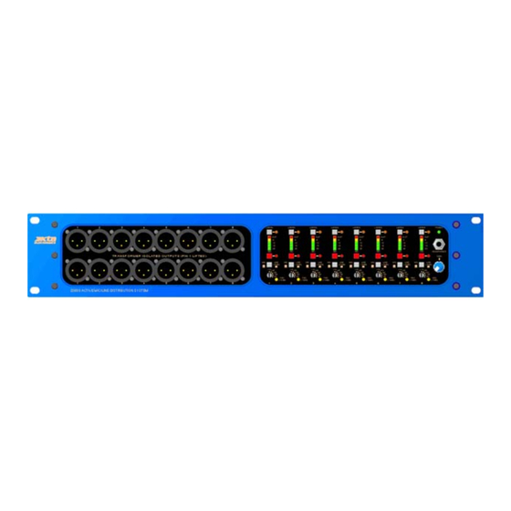
The XTA DS800 Mic / Line Distribution System is a high quality active distribution / splitter unit containing eight channels of processing in 2U of rack space. Each... -
Page 7: Front Panel Functions
8. Pad (-10dB) – indicates 48V phantom power detected on the output ‘Mon’ XLR, which will automactically switch in a 10dB pad on the channel. 9. Headphone Level – controls the level of the headphone output. 10. Headphone Socket. 11. Power – power indicator. DS800 Page 5... -
Page 8: Rear Panel Functions
5. Solo Bus In XLR – used for multiple unit applications, normally connected to the Solo Bus Out XLR of the unit below in the rack. See 4 above. 6. Mains Inlet – combined IEC inlet, fuse and power switch. DS800 Page 6... -
Page 9: Block Diagram
Block Diagram DS800 Page 7... -
Page 10: Grounding
DS800 from a star point (single phase). Cooling If you mount several DS800’s in a rack Please fan cool the rack with a minimum of one fan @ 35CFM per 6 DS800’s, blowing air into the rack (positive pressure). This will extend the life and the reliability of the units. -
Page 11: System Wiring
System Wiring Bussing Option In a standard factory supplied form the DS800 is set-up so that each of it’s 8 Inputs is connected to it’s corresponding output drive section, which effectively has 4 outputs (two isolateds, FOH and MON). Jumper links that are assessable internally are provided, that enable this configuration to be changed. - Page 12 By swapping the jumper links, numerous configurations are possible. Shown below are two possible set-ups. DS800 Page 10...
-
Page 13: Specifications
< 40 watts. Weight 8.1kg. Net (9.5kg. Shipping) Size 3.5"(2U) * 19" * 12.2" (88 * 482 * 312mm) excluding connectors. Options = Transformers available. Due to continuing product improvement the above specifications are subject to change. DS800 Page 11... -
Page 14: Warranty
During the warranty period, XTA will, at it's discretion, either repair or replace products which prove to be defective, provided that the product is returned, shipping prepaid, to an authorised XTA service facility.
Need help?
Do you have a question about the DS800 and is the answer not in the manual?
Questions and answers