Table of Contents
Advertisement
Advertisement
Table of Contents
Troubleshooting

Related Manuals for Harman Kardon AVR 260


Summary of Contents for Harman Kardon AVR 260
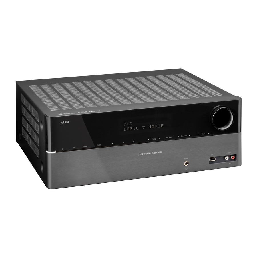
- Page 1 AVR 260 AUDIO/VIDEO RECEIVER OWNER’S MANUAL...
-
Page 2: Table Of Contents
TABLE OF CONTENTS Safety Information Introduction Front Panel Controls Rear Panel Connections Remote Control Functions Installation and Connections Audio Equipment Connections HDMI Input Connections HDMI Output Connections Analog and Digital Input Connections Video Equipment Connections System and Power Connections Main Room Remote Control Extension Zone 2 IR Link Multiroom Audio Connection Speaker Selection... -
Page 3: Safety Information
Important Safety InStructIonS Read these instructions. Keep these instructions. Heed all warnings. Follow all instructions. Do not use this apparatus near water. Clean only with a dry cloth. Do not block any ventilation openings. Install in accordance with the manufacturer’s instructions. Do not install near any heat sources such as radiators, heat registers, stoves or other apparatus (including amplifiers) that produce heat. -
Page 4: Introduction
True HD and DTS®-HD Master Audio™ and the latest 7.1 channel versions of Harman's own Logic 7 technology. The AVR 260 has been engineered so that it is easy to take advantage of all the power of its digital technology. Full-color, high-definition, multi- language on-screen menus, fully color coded connection jacks and terminals make installation fast and simple. - Page 5 Harman Kardon invented the high- fidelity receiver more then fifty years ago. With state-of-the-art circuitry and time-honored circuit designs, the AVR 260 is the perfect combination of the latest in digital audio technology, a quiet yet powerful analog amplifier in an elegant, easy-to-use package.
-
Page 6: Front Panel Controls
FRONT-PANEL CONTROLS Resolution Audio Effects Info 0 Volume Control: Turn this knob clockwise to increase the volume, counterclockwise to decrease the volume. If the AVR is muted, adjusting volume control will automatically release the unit from the silenced condition. 1 System Power Control: When the Main Power Switch on the rear panel is “ON,”... - Page 7 D Speaker/Channel Input Indicators: These indicators are multipurpose, indicating either the speaker type selected for each channel or the incoming data-signal configuration. The left, center, right, right surround and left surround speaker indicators are composed of three boxes, while the subwoofer is a single box. The center box lights when a “Small”...
-
Page 8: Rear Panel Connections
REAR-PANEL CONNECTIONS � � � � � � � � � � � � � NOTE: To assist in making the Front Left:...White correct connections for multichannel Front Right: ...Red input/output and speaker Center: ...Green connections, all connection jacks and terminals have been color coded Surround Left: ...Blue in conformance with the latest CEA Surround Right: ...Gray... - Page 9 C RS-232 Reset: This switch is only used during a software upgrade. A standard processor reset is performed by pressing and holding the front- panel OK Button while the receiver is in Standby. D Front Speaker Outputs: Connect these outputs to the matching + or –...
- Page 10 NOTE ON VIDEO CONNECTIONS: When connecting a video source product such as a VCR, DVD player, satellite receiver, cable set-top box, personal video recorder or video game to the AVR 260, you may use either a composite or S-video connection, but not both.
-
Page 11: Remote Control Functions
AVR Power On AVR Power Off Source Selectors Audio Effects Button Transport Controls Menu Navigation LKM N Sleep Button Main Tuning Buttons Last Button Numeric Keys Video Mode Button Menu Button Activity Button Back/Exit Button Master Volume Disc Menu Button Mute Button Surround Mode Button Device Power OFF Button... - Page 12 REMOTE CONTROL FUNCTIONS The remote is capable of operating the AVR 260 and most Harman Kardon CD changers or players, CD Recorders and Blu-ray players, using the control codes that are part of the remote. AVR Power On: When the AVR 260 is in the Standby mode, as indicated by the Power Indicator 2 glowing amber, press this button to turn the unit on.
-
Page 13: Installation And Connections
If you find that 5.1 Dolby Digital or DTS audio is not available on the HDMI connection, it will be necessary to make an additional connection between the source and the AVR 260 to either the Coaxial NJ or Optical RH Digital Inputs. -
Page 14: Hdmi Output Connections
NOTE: If you wish for your digital source device to be available for use by the multiroom system, you will need to connect its analog audio outputs to the appropriate inputs on the AVR 260, as the multiroom system is not capable of distributing digital signals to the remote zone. -
Page 15: Video Equipment Connections
When connecting wires to the speakers, be certain to observe proper polarity. Note that the positive (+) terminal of each speaker connection now carries a specific color code as noted on page 8. However, most speakers will still use a red terminal for the postive (+) connection. -
Page 16: System And Power Connections
INSTALLATION AND CONNECTIONS SyStem anD power connectIonS The AVR is designed for flexible use with multiroom systems, external control components and power amplifiers. main room remote control extension If the receiver is placed behind a solid or smoked glass cabinet door, the obstruction may prevent the remote sensor from receiving commands. - Page 17 The speakers should be no more than 2 meters behind the rear of the seating area. It is appropriate to configure the AVR 260 for either 5.1- or 7.1-channel operation, but not for 6.1 channels. When 6.1-channel program material or a 6.1-channel processing mode is in use, material for the surround back channel...
-
Page 18: System Configuration
Main Menu is on screen, pressing the Back/Exit Button will exit the menu system. SyStem Setup The AVR 260 features an advanced memory system that enables you to establish different configurations for digital input and surround mode for each input source. This flexibility enables you to custom tailor the way in which you listen to each source and have the AVR memorize them. -
Page 19: Audio And Video Input Selection
audio and Video Input Selection Please see Table A1 in the appendix for the factory default input assignments for each source. You may assign any available input to any source using the Source Info menu, accessible either by pressing the AVR Settings Button W and selecting the Setup Source line, or by pressing the Info Settings Button W for direct access. -
Page 20: Resolution From Source
EzSet/EQ microphone at the correct height. The microphone includes a threaded insert on the bottom for tripod mounting. Step 3: Plug the EzSet/EQ microphone into the AVR 260’s Headphone Jack 3, making certain that the mini-plug to 1/4" phone plug adaptor supplied with the microphone is firmly connected. - Page 21 Basic Operation section of this manual on page 30 to learn how to operate AVR 260. For those situations where you may wish to make a change to the settings...
-
Page 22: Manual Setup
SYSTEM CONFIgURATION manual Setup The AVR 260 is flexibly designed to be used with almost any loudspeakers available. The flexibility arises from the AVR 260’s capability to be configured to match the characteristics of your particular speakers, and to compensate for the acoustic characteristics of your room. -
Page 23: Number Of Speakers
The setting for the surround back speakers includes a third option: Zone 2. The AVR 260 is among the few receivers in its class that is capable of multizone operation, allowing placement of a pair of speakers in another room with listeners in the remote room enjoying either the same program as in the main room or a different source. -
Page 24: Adjust Speaker Distance Menu
SYSTEM CONFIgURATION Sub Mode Move the cursor to the Sub Mode line to program bass management for the subwoofer. The subwoofer’s setting depends upon how you programmed the front left and right speakers. • If you set the front speakers to a numeric crossover frequency, the subwoofer setting will be LFE, and you won’t be able to change it. - Page 25 OK Button and use the level as desired between –10dB and +10dB. All channels default to 0dB. If you would like to set your levels using the AVR 260’s internal test tone, adjust the TEST TONE line as follows.
-
Page 26: Operation
OPERATION SurrounD moDe cHart MODE FEATURES Dolby Digital Plus An enhanced version of Dolby Digital encoded more efficiently, Dolby Digital Plus has the capacity for additional discrete channels and for streaming audio from the internet, all with enhanced audio quality. Source material may be delivered via HDMI, or decoded to Dolby Digitaland transmitted via S/P-DIF coaxial or optical digital audio. - Page 27 MODE FEATURES DTS Neo:6 Cinema These two modes are available when any analog source is playing to create a six-channel surround presentation from conventional DTS Neo:6 Music Matrix-encoded and traditional Stereo sources. Select the Cinema version of Neo:6 when a program with any type of analog Matrix surround encoding is present.
-
Page 28: Basic Operation
OPERATION BaSIc operatIon Once you have completed the setup and configuration of the AVR, it is simple to operate and enjoy. The following instructions should be followed for you to maximize your enjoyment of your new receiver: turning the aVr on or off •... -
Page 29: Video Troubleshooting Tips
VIDEO TROUBLESHOOTING TIPS: If a video source is playing and there is no picture: • Check that you have selected the source to which the video input was assigned. • Check the wires for a loose or incorrect connection. • Check that you have selected the correct video input on the display device (TV). -
Page 30: Surround Mode Selection
OPERATION Surround mode Selection One of the most important features of the AVR 260 is its ability to reproduce a full multichannel surround sound field from digital sources, analog matrix surround encoded programs and standard stereo or even mono programs. - Page 31 The first number indicates the number of front channels in the signal: “1” represents a monophonic recording, usually an older program that has been digitally remastered or, more rarely, a modern program for which the director has chosen a special effect. “2”...
-
Page 32: Surround Modes
Feel free to experiment and simply cycle through all of the available surround modes at any time; you cannot cause any problems for the AVR 260 by doing Note: To access 6.1- and 7.1-channel modes, such as Dolby Digital EX, DTS- ES, Logic 7 (7.1 modes), DTS Neo:6 (6.1 modes), and 7-channel Stereo, you... -
Page 33: Tape Recording
tape recording In normal operation, the audio or video source selected for listening through the AVR is sent to the record outputs. This means that any program you are watching or listening to may be recorded simply by placing machines connected to the outputs for Analog Outputs 3 or Video 1 Outputs P7 in the record mode. -
Page 34: Surround Amplifier Channel Assignment
MULTIROOM OPERATION When the Zone 2 menu appears, the blue cursor bar will be at the line. Since this line is used to turn the system on and off, do not make an adjustment here unless you wish to turn the system on at this time. To turn the system on, press the OK Button V once, to turn it off again, press once more. -
Page 35: Video Adjustments
When upscaling video materials from a lower resolution to a higher one (the AVR 260 upscales to a maximum of 1080p), the processor is adding pixels to the original image. -
Page 36: Audio Effects
Audio Effects Button or the Back/Exit Button to clear the screen. aDVanceD featureS The AVR 260 is equipped with a number of ad vanced features that add extra flexibility to the unit’s operation. While it is not necessary to use these features to operate the unit, they provide additional options that you may wish to use. -
Page 37: Volume Units
General aVr Settings Volume Units: Select whether volume is displayed in the conventional decibel scale or on a numeric scale from 0 to 100. When the decibel scale is used, 0dB is the maximum volume, with lower volumes measured as negative values. -
Page 38: Tuner Operation
0 again first. rDS operatIon The AVR 260 is equipped with RDS (Radio Data System), which brings a wide range of information to FM radio. Now in use in many countries, RDS... - Page 39 program Search (pty) An important feature of RDS is its capability of encoding broadcasts with Program Type ( ) codes that indicate the type of material being broadcast. The following list shows the abbreviations used to indicate each PTY, along with an explanation of the PTY: NEWS: •...
-
Page 40: Programming The Remote
PROgRAMMINg ThE REMOTE The AVR 260 is equipped with a powerful remote control that will control not only the receiver’s functions, but also most popular brands of audio and video equipment, including CD players, TV sets, cable boxes, VCRs, satellite receivers and other home-theater equipment. -
Page 41: Code Readout
code readout When the code has been entered using the Auto Search method, it is always a good idea to find out the exact code so that it may be easily reentered if necessary. You may also read the codes to verify which device has been pro- grammed to a specific Control Selector button. -
Page 42: Notes On Using The Avr Remote With Other Devices
The AVR 260 remote’s punch-through feature allows you to select one component for the remote to operate, while simultaneously setting certain groups of controls to operate another component. For example, while using the AVR to control surround modes and other audio functions, you may operate the transport controls of your DVD player. -
Page 43: Setup Code Tables
Maker (Brand) Name Code Number (3 digit) List HARMAN KARDON BRIDGE HARMAN KARDON RADIO HARMAN KARDON ADMIRAL 105 088 023 AIWA AKAI 093 089 056 053 042 022 020 011 ALBA 040 020 ARC EN CIEL 059 056 024 019 017 ARCAM ARISTONA 086 060 048 047 033 025 023 022... - Page 44 SETUP CODE TABLES SAMSUNG 024 003 002 SATBOX SCIENTIFIC ATLANTA 026 025 006 005 TELESERVICE TIVO 029 030 TUDI UNITED CABLE VISIOPASS WESTMINSTER CABLE AIWA AKAI ALBA 411 301 AMSTRAD ANKARO ASTRO 483 482 481 480 479 478 477 476 BARCOM BLAUPUNKT 390 338...
- Page 45 AUX_VCR AIWA 452 448 421 416 373 355 344 339 AKAI 450 455 449 403 392 390 353 344 ALBA 436 421 373 368 361 AMSTRAD 448 407 339 ANITECH ARC EN CIEL 390 344 ARISTONA 409 391 349 ASTRA ASTRO SOUND ATLANTIC AUDIOSONIC...
- Page 46 FUNCTION LIST 10 11 35 36 37 38 52 53 54 55 BUTTON Name AVR Zone 2 AVR Power On AVR Power On AVR Power On AVR Power Off AVR Power Off AVR Power Off Device Power On Device Power Off CBL/SAT INPUT SEL INPUT SEL...
- Page 47 Server DMC250 DMC1000 AVR Power On AVR Power On AVR Power On AVR Power Off AVR Power Off AVR Power Off Power On Power Off INPUT SEL INPUT SEL INPUT SEL INPUT SEL INPUT SEL INPUT SEL Radio Radio Radio INPUT SEL INPUT SEL INPUT SEL...
-
Page 48: Troubleshooting Guide
TROUBLEShOOTINg gUIDE SYMPTOM CAUSE • Unit does not function when Main No AC Power Power Switch 0 is pushed Display lights, but no sound or • Intermittent input connections picture • Mute is on • Volume control is down • No sound from any speaker;... -
Page 49: Technical Specifications
Audio Section Stereo Mode, Continuous Average Power (FTC) 65 Watts per channel, 20Hz–20kHz, @ <0.07% THD, both channels driven into 8 ohms Seven-Channel Surround Modes Power Per Individual Channel, with all channels driven Front L & R channels: 50 Watts per channel @ <0.07% THD, 20Hz–20kHz into 8 ohms Center channel: 50 Watts... -
Page 50: Appendix - Settings Worksheet
APPENDIX – SETTINgS WORKShEET appendix – Default settings, worksheets, remote product codes Table A1 – Recommended Source Component Connections Device Type AVR Source Cable TV, satellite TV, HDTV CBL/SAT or other device that delivers television programs DVD Audio/Video, SACD, Blu- ray Disc, HD-DVD player Media Server, including Media Server... - Page 51 Table A3 – Speaker/Channel Setting Defaults All Digital and 2-Channel Analog Audio Input Audio Inputs Left/Right Speakers Center Speaker Left/Right Surround Speakers Left/Right Surround Back Speakers Subwoofer Left/Right Speakers Crossover 100Hz Center Speaker Crossover 100Hz Left/Right Surround Speakers Crossover 100Hz Left/Right Surround Back Speakers Crossover 100Hz Subwoofer Mode Subwoofer Size...
- Page 52 APPENDIX – SETTINgS WORKShEET Table A6 – Audio Effects Settings Default Cable/Sat Tone Control Treble Bass LFE Trim Night Mode Table A7 – Video Modes Settings Default Cable/Sat Video Mode Processor Off Brightness* Contrast* Color* Sharpness* Picture Adjust Auto Fit Noise Reduction** MPEG Noise Reduction**...
- Page 53 Table A9 – Remote Control Codes Source Input Cable/Sat DVD/Blu-ray Media Server Game Table A10 – System Settings Feature Front Panel Dimmer Volume Units Volume Default Volume Default Level Unit of Measure Language HDMI Audio to TV OSD Transparency Volume/Status Messages Menus Setup and Slide-In Menus Screen Saver...
- Page 54 8500 Balboa Blvd., Northridge, CA 91329 www.harmankardon.com © 2009 Harman International Industries, Incorporated. All rights reserved. Part No. CQX1A1318W...