Table of Contents
Advertisement
Quick Links
AssEMbLy AnD OpERAtIOn InstRUCtIOns
Due to continuing improvements, actual product may differ slightly from the product described herein.
Visit our website at: http://www.harborfreight.com
tO pREVEnt sERIOUs InjURy, READ AnD UnDERstAnD
ALL WARnInGs AnD InstRUCtIOns bEfORE UsE.
Copyright
2007 by Harbor Freight Tools
©
manual or any artwork contained herein may be reproduced in any shape or form
without the express written consent of Harbor Freight Tools.
for technical questions or replacement parts, please call 1-800-444-3353.
220 VAC
MIG WELDER
Model
3491 Mission Oaks Blvd., Camarillo, CA 93011
*220 VAC refers to input voltage.
DUAL
*
55525
. All rights reserved. No portion of this
®
®
Advertisement
Table of Contents

Related Manuals for Chicago Electric 55525


Summary of Contents for Chicago Electric 55525
- Page 1 2007 by Harbor Freight Tools © manual or any artwork contained herein may be reproduced in any shape or form without the express written consent of Harbor Freight Tools. for technical questions or replacement parts, please call 1-800-444-3353. DUAL Model 55525 .
-
Page 2: Table Of Contents
Lists and Diagrams ... 27 Wiring schematic ... 27 parts List ... 28 Assembly Diagram ... 29 tROUbLEsHOOtInG ... 31 WARRAnty ... 33 for technical questions, please call 1-800-444-3353; SKU 55525 troubleshooting section at end of manual. Contents Page 2... -
Page 3: Product Specifications
Power tools create sparks which may ignite the dust or fumes. for technical questions, please call 1-800-444-3353; SKU 55525 troubleshooting section at end of manual. 35 ~ 110 Amps 15% @ 110 Amps / 100% @ 35 Amps (Refer to chart and explanation on page 18) 220 Volt / 60 Hz / Single Phase / 24.5 Amps... -
Page 4: Electrical Safety
Remove adjusting keys or wrenches before turning the power tool on. A wrench or a key that is left attached to a rotating part of the power tool may result in personal injury. for technical questions, please call 1-800-444-3353; SKU 55525 troubleshooting section at end of manual. ELECtRICAL sAfEty pERsOnAL sAfEty... - Page 5 “Inspection, Maintenance, And Cleaning” section of this manual. Use of unauthorized parts or failure to follow maintenance instructions may create a risk of electric shock or injury. for technical questions, please call 1-800-444-3353; SKU 55525 troubleshooting section at end of manual. tOOL UsE AnD CARE sERVICE...
-
Page 6: Specific Safety Rules
220 volt, 3-hole outlet that is properly grounded. Maintain labels and nameplates on the Welder. These carry important informa- tion. If unreadable or missing, contact Harbor Freight Tools for a replacement. Avoid unintentional starting. Make sure you are prepared to begin work before turning on the Welder. - Page 7 Work in a confined area only if it is well ventilated, or while wearing an air-sup- plied respirator. • Follow OSHA guidelines for Permissible Exposure Limits (PEL’s) for various fumes and gases. for technical questions, please call 1-800-444-3353; SKU 55525 troubleshooting section at end of manual. Page 7...
- Page 8 Keep cylinders away from any electrical circuits, including welding circuits. • Keep protective cap in place over the valve except when the cylinder is in use. for technical questions, please call 1-800-444-3353; SKU 55525 troubleshooting section at end of manual. • Heart Disease •...
-
Page 9: Grounding
There are certain applications for which this Welder was designed. It will do the job better and more safely at the rate for which it was intended. Do not modify this Welder, and do not use this Welder for a purpose for which it was not intended. -
Page 10: Extension Cords
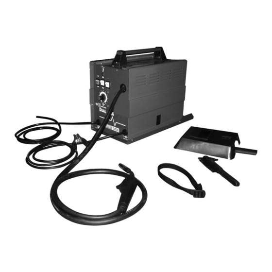
Lists on pages 28 through 30 are included, in addition to the face shield, wire brush/ hammer, and strap (for cylinder connection). If any parts are missing or broken, please call Harbor Freight Tools at the number shown on the cover of this manual as soon as possible. -
Page 11: Assembly Instructions
See numbered steps in illustration to the right. tO InstALL A WIRE spOOL Lift the Access Panel (12) of the Welder to expose the Wire Feed Assembly. Unscrew and remove the Wing Nut (40) and Spool Knob (39). Install a 2 lb. Spool (not included) onto... -
Page 12: To Route The Wire
ADjUstInG KnOb Lay the Torch Cable out in a straight line so that the Welding Wire moves through it easily. Leave the Access Panel (12) of the Welder open so that the Wire Feed Assembly can be observed. Remove the Gun Nozzle (15h) and Contact Tip (15g). (see figure f, next page.) for technical questions, please call 1-800-444-3353;... - Page 13 2 to 3 inches away. If the Wire stops instead of bending, turn the Welder Off. Unplug the unit from its electrical outlet. Then, slightly tighten the Tension Adjusting Knob (10b) on the Wire Feed Assembly. (see figure E.)
-
Page 14: To Change Wire Settings
CHAnGE WIRE sEttInGs WARnInG! Make sure to turn off the Welder and unplug it from its electrical outlet prior to changing wire settings. Open the Access Panel (12) of the Welder to expose the Wire Feed Assembly. sCREW (10l) Loosen, and lower the Tension Adjusting Knob (10b) on the Wire Feed Assembly. -
Page 15: Setting The Gun Polarity For Wire Type
Always read and follow wire manufacturer’s recom- mended polarity. A. positive (+) Output terminal polarity Changeover Label negative (–) Output terminal Red Cable black Cable for technical questions, please call 1-800-444-3353; SKU 55525 troubleshooting section at end of manual. fIGURE H Page 15... -
Page 16: To Install A Gas Cylinder
To use CO lator/flow meter (neither one included). Thread the provided strap through the slots on the back of the welder. With assis- tance, set the cylinder onto the shelf at the back of the welder. Secure the cylinder in place with the strap. -
Page 17: Operating Instructions
Welder can safely produce a particular welding current. for example, this Welder, with a 15% duty cycle at 110 Amps (setting Max 2), must be al- lowed to rest for at least 8 minutes and 30 seconds after every minute and 30 seconds of continuous weld at 110 Amps. -
Page 18: Setting Up The Weld
Overload Indicator Light (28): If too much current is drawn from the Welder, the Overload Protector will activate. The RED Overload Indicator Light will illuminate and the Welder will automatically turn off until it cools down. If this happens, turn the Power Switch to its “Off” position and wait approximately 20 minutes. -
Page 19: Holding The Welding Torch
(see figure L.) Make sure the Power Switch is in its “Off” position. Then plug Power Cord of the Welder into a dedicated, 220 VAC, 25 amp line with delayed action type circuit breaker or fuse. While holding the Welding Torch (15), with the Welding Wire clearly out of the way of any grounded objects, turn the Power Switch to its “On”... -
Page 20: Weld Settings Chart
Welding Instructions continued on next page. for technical questions, please call 1-800-444-3353; SKU 55525 Page 20 troubleshooting section at end of manual. - Page 21 For a wider weld, draw the Welding Wire back and forth across the joint in a curve. This is called a “weave bead”. note: If too much current is drawn from the Welder, the internal Thermal Overload Protec- tor will activate. The Overload Indicator Light (28) will illuminate and the Welder will automatically turn off.
-
Page 22: Weld Diagnosis
Keep arc on leading edge of weld puddle. Hold gun at proper angles as stated under Holding The Torch on page 19. for technical questions, please call 1-800-444-3353; SKU 55525 troubleshooting section at end of manual. WELD DIAGnOsIs Weld penetration... - Page 23 * this test WILL damage the weld it is performed on. this test is OnLy an indicator of weld tech- nique and is not intended to test working welds. for technical questions, please call 1-800-444-3353; SKU 55525 troubleshooting section at end of manual. Crooked/wavy bead VIew...
-
Page 24: When The Weld Is Completed
Make sure not to damage the weld or material when striking it. The wire brush can then be used to help remove oxidation and some fine spat- ter. for technical questions, please call 1-800-444-3353; SKU 55525 troubleshooting section at end of manual. Page 24... -
Page 25: Inspection, Maintenance, And Cleaning
Periodically open the Access Panel (12) from the unit and, using compressed air, blow out all dust and debris from the interior. Always store the Welder in a clean, dry, safe location out of reach of children and other unauthorized people. -
Page 26: Replacing The Welding Torch Liner
REpLACInG tHE WELDInG tORCH LInER Switch welder off, disconnect power, and discharge electrode to ground before proceeding. Secure welding wire to the spool, cut it near the spool, and remove it from the torch and cable. Gently twist and slide the Locking Collar (15b) off the torch and onto the Protective Sleeve (15a). -
Page 27: Parts Lists And Diagrams
LIsts AnD DIAGRAMs WIRInG sCHEMAtIC for technical questions, please call 1-800-444-3353; SKU 55525 Page 27 troubleshooting section at end of manual. -
Page 28: Parts List
Locking Collar Lower Housing Trigger Switch Body Head Tube *Wire feed mechanism includes parts 10a-10j, & 11 for technical questions, please call 1-800-444-3353; SKU 55525 troubleshooting section at end of manual. pARts LIst qty. part Description Contact Tip (.8 mm) -
Page 29: Assembly Diagram
AssEMbLy DIAGRAM for technical questions, please call 1-800-444-3353; SKU 55525 Page 29 troubleshooting section at end of manual. - Page 30 AssEMbLy DIAGRAM (COntInUED) Wire feed Mechanism (10) for technical questions, please call 1-800-444-3353; SKU 55525 Page 30 troubleshooting section at end of manual.
-
Page 31: Troubleshooting
CERtAIn to shut off the Welder, disconnect it from power, and discharge the torch to ground before adjusting, cleaning, or repairing the unit. Wire feed motor runs but wire does not feed properly pOssIbLE CAUsEs AnD sOLUtIOns Insufficient wire feed pressure: Increase wire feed pressure properly - follow instructions on page 12-13. -
Page 32: Weak Arc Strength
(continued) be CERtAIn to shut off the Welder, disconnect it from power, and discharge the torch to ground before adjusting, cleaning, or repairing the unit. Welder does not function when switched on pOssIbLE CAUsEs AnD sOLUtIOns tripped thermal protection device: Shut the welder’s switch to off and allow it to cool for at least 20 minutes. -
Page 33: Warranty
LIMIteD 90 DAy/1 yeAr wArrAnty Harbor Freight Tools Co. makes every effort to assure that its products meet high quality and durability standards, and warrants to the original purchaser that for a period of ninety days from date of purchase that the torch, liner, wire feed mechanism (if applicable), welding clamps, electrode holders, cables and accessories packed with the welder are free of defects in materials and workmanship.