Sign In
Upload
Download
Table of Contents
Contents
Add to my manuals
Delete from my manuals
Share
URL of this page:
HTML Link:
Bookmark this page
Add
Manual will be automatically added to "My Manuals"
Print this page
×
Bookmark added
×
Added to my manuals
Manuals
Brands
3M Manuals
Projector
213
Illustrated parts breakdown
3M 213 Illustrated Parts Breakdown
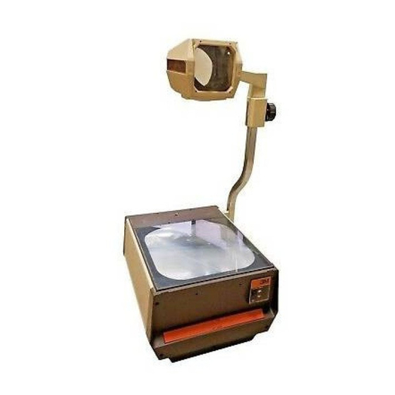
Overhead projector 213 series
Hide thumbs
1
2
3
4
Table Of Contents
5
6
7
8
9
10
11
12
13
14
15
16
17
18
19
20
21
22
23
24
25
26
27
28
29
page
of
29
Go
/
29
Contents
Table of Contents
Bookmarks
Table of Contents
Table of Contents
Overview
Base Assembly
Section 1 BASE ASSEMBLY
Rear End Assembly
Lamp Changer/Lamp Holder Assembly
Front Control Module Assembly
Projection Head Assembly (Articulate)
Projection Head Assembly (Non-Articulate)
Projection Head Assembly (Open)
Post Mount Arm and Focus Assembly
Roller Attachment
Section 9 ROLLER ATTACHMENT
Advertisement
Quick Links
1
Table of Contents
2
Overview
3
Base Assembly
4
Section 1 Base Assembly
5
Lamp Changer/Lamp Holder Assembly
6
Front Control Module Assembly
Download this manual
213 Series Overhead Projector
Illustrated Parts Breakdown
For:
213
395
3M Visual Systems Division
6801 River Place Boulevard
Austin, Texas 78726-9000
313
394
413
429
Printed in U.S.A.
E3M 6/96 78-6970-4959-7 Rev. B
Table of
Contents
Previous
Page
Next
Page
1
2
3
4
5
Advertisement
Table of Contents
Need help?
Do you have a question about the 213 and is the answer not in the manual?
Ask a question
Questions and answers
Related Manuals for 3M 213
Projector 3M Overhead Projector 2660 Operator's Manual
Overhead projector (5 pages)
Projector 3M Overhead Projector 2660 Operating Instructions Manual
Overhead projector (13 pages)
Projector 3M 2660 Illustrated Parts Breakdown
Overhead projector (23 pages)
Projector 3M 2770 Illustrated Parts Breakdown
Overhead projector (26 pages)
Projector 3M 2770 Owner's Manual
Overhead projector owner's manual (6 pages)
Projector 3M 2100 Illustrated Parts Breakdown
Overhead projector (37 pages)
Projector 3M 2100 Service Manual
Overhead projector (30 pages)
Projector 3M 2000 Illustrated Parts Breakdown
Overhead projector (27 pages)
Projector 3M 2000 Operating Instructions Manual
Overhead projector (15 pages)
Projector 3M 2600 ANSI lumens Brochure & Specs
(2 pages)
Projector 3M 1700 Operating Instructions Manual
3m overhead projector operating instructions model no. 1700 (9 pages)
Projector 3M X20 Operator's Manual
(73 pages)
Projector 3M MP 180 Operator's Manual
3m mp 180: user guide (66 pages)
Projector 3M MP180 Operator's Manual
(50 pages)
Projector 3M 9800 Service Manual
Overhead projector (52 pages)
Projector 3M MP8635B Operator's Manual
(36 pages)
This manual is also suitable for:
313
394
395
413
429
Table of Contents
Save PDF
Print
Rename the bookmark
Delete bookmark?
Delete from my manuals?
Login
Sign In
OR
Sign in with Facebook
Sign in with Google
Upload manual
Upload from disk
Upload from URL


Need help?
Do you have a question about the 213 and is the answer not in the manual?
Questions and answers