Table of Contents
Advertisement
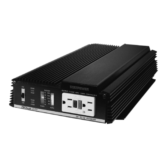
PROwatt 1500/12 volt
PROwatt 1500/24 volt
Statpower Technologies Corporation
7725 Lougheed Highway
Burnaby, BC V5A 4V8
Canada
PROwatt is a trademark of Statpower Technologies Corporation.
Copyright © 1996, 1997 Statpower Technologies Corporation. All rights reserved.
TM
TM
POWER INVERTER
Owner's
Manual
Tel: (604) 420-1585
Fax: (604) 420-1591
Internet address: http://www.statpower.com
Advertisement
Table of Contents
Troubleshooting

Related Manuals for Statpower PROwatt 1500/12 volt


Summary of Contents for Statpower PROwatt 1500/12 volt
- Page 1 Owner’s Manual Statpower Technologies Corporation Tel: (604) 420-1585 7725 Lougheed Highway Fax: (604) 420-1591 Burnaby, BC V5A 4V8 Internet address: http://www.statpower.com Canada PROwatt is a trademark of Statpower Technologies Corporation. Copyright © 1996, 1997 Statpower Technologies Corporation. All rights reserved.
-
Page 2: Table Of Contents
7 Maintenance................................22 8 Warranty ................................22 8.1 Warranty Terms.............................22 8.2 To Obtain Warranty Service.........................22 9 Specifications ..............................24 9.1 Electrical Performance ..........................24 9.2 Dimensions............................24 PROwatt is a trademark of Statpower Technologies Corporation. Copyright © 1996, 1997 Statpower Technologies Corporation. All rights reserved. -
Page 3: Introduction
1 Introduction Your new PROwatt 1500 inverter is a member of the most advanced line of dc to ac inverters available today. It will give you years of dependable service in your boat, RV, service vehicle or remote home. To get the most out of your PROwatt 1500, it must be installed and used properly. Please read the installation and operating instructions in this manual carefully before installing and using your PROwatt 1500. -
Page 5: Prowatt 1500 Output Waveform
2.2 PROwatt 1500 Output Waveform The AC output waveform of the PROwatt 1500 is called a "quasi-sine wave" or a "modified sine wave". It is a stepped waveform that is designed to have characteristics similar to the sine wave shape of utility power. A waveform of this type is suitable for most AC loads, including linear and switching power supplies used in elec- tronic equipment, transformers, and motors. -
Page 6: Quick Checkout
3 Quick Checkout This section will give you the information you need to quickly hook-up your PROwatt 1500 and check its per- formance before going ahead with permanent installation. You will need the following: a) a 12 volt DC power source (24 volt for PW1500/24) b) two cables to connect the power source to the PROwatt 1500 c) a test load that can be plugged into the AC receptacle on the PROwatt 1500. -
Page 7: Test Loads
power source, must be terminated with a lug or other connector that allows a secure, low resistance connection to be made to the power source. For instance, if the power source is a battery, the cable must be terminated with a battery terminal that clamps to the post on the battery. -
Page 8: Installation
WARNING! You may observe a spark when you make this connection since current may flow to charge capaci- tors in the PROwatt 1500. Do not make this connection in the presence of flammable fumes. Explosion or fire may result. STEP 6 If you are using a DC power supply as the power source, switch it on. Set the ON/OFF switch on the PROwatt 1500 to the ON position. -
Page 9: Battery Type
The battery you use strongly affects the performance you can expect from your PROwatt 1500. It is important to connect the PROwatt 1500 to the correct size and type of battery. The following information will help you select the appropriate batteries for your application. Battery Type The lead-acid battery which is probably most famil- iar is the starting battery in your automobile. -
Page 10: Battery Sizing
Battery Sizing Unfortunately, there are a number of different standards for rating battery energy storage capacity. 12 volt Auto- motive starting batteries are normally rated by cranking amps. This is not a relevant rating for continuous use. Deep-cycle batteries are rated either by reserve capacity in minutes or by ampere-hour capacity. Battery reserve capacity is a measure of how long a battery can deliver a certain amount of current - usually 25 amperes. -
Page 11: Using Multiple Batteries
INVERTER BATTERY SIZE OUTPUT BCI GROUP SIZE: 20NF DUAL 8D's POWER TYPICAL LOAD RESERVE CAPACITY 90 MINUTES 140 MINUTES 180 MINUTES 400 MINUTES 900 MINUTES (WATTS) AMP-HRS: OPERATING TIME: STEREO SYSTEM 9 HOURS 14 HOURS 20 HOURS 40 HOURS 80 HOURS OPERATING TIME: 19"... -
Page 12: Battery Tips
Figure 8. Recommended Battery Configuration for Heavy-Duty Applications Note: PW1500/24 model inverter only: 24 Volt systems typically have 2 x 12 Volt batteries connected in series. Battery Tips 1. With the exception of sealed, gel cell batteries, lead-acid batteries emit hydrogen and oxygen gases, and sulfu- ric acid fumes when recharging. -
Page 13: Alternators And Charging Systems
4. If your batteries are not the "maintenance-free" type, check the electrolyte fluid level at least once a month. Use only distilled water to replenish the electrolyte fluid. Excessive fluid loss is a sign of overcharging. 5. Connections to battery posts must be made with permanent connectors that provide a reliable, low-resistance connection. -
Page 14: Cables
Your batteries may also be recharged from alternative energy sources such as solar panels, wind, or hydro sys- tems. Make sure that you use the appropriate battery charge controller for your energy source. Do not operate the PROwatt 1500 directly from a charging source such as an alternator or solar panel. The PRO- watt must be connected to a battery or a well-regulated, high-current DC power supply to work properly. - Page 15 In many cases you can plug your AC loads directly into the AC receptacle on the front panel of the PROwatt 1500. In other installations you may wish to connect the output of the PROwatt 1500 to existing AC wiring. The PROwatt 1500 is equipped with internal terminals to allow permanent connection to existing AC wiring.
- Page 16 When installing the PROwatt 1500 into an electrical system that also uses power from a generator or the util- ity line, you must include a means of switching between the PROwatt and the other power source that never al- lows both to be connected to the AC distribution system at the same time.
-
Page 17: Ground Wiring
Figure 12. Wiring to AC Breaker Panel Ground Wiring The PROwatt 1500 has a lug on the rear panel labeled Chassis Ground. This is to connect the chassis of the PROwatt 1500 to ground. The ground terminal in the AC outlet on the front panel of the PROwatt 1500 is con- nected to the chassis. -
Page 18: Dc Wiring
DC Wiring STEP 1 Ensure that the ON/OFF switch on the PROwatt 1500 is in the OFF position. If you are using a battery selector switch, switch it off as well. STEP 2 Connect the cables to the power input terminals on the rear panel of the PRO- watt 1500. -
Page 19: Remote Panel
4.5 Remote Panel The PROwatt remote switch allows your PROwatt inverter to be switched on/off from a convenient remote loca- tion while the inverter is mounted out of sight. Installation Instructions: 1. Cut out the template, located on the back page of the manual (Figure 14), and position it on the wall where the switch is to be mounted. -
Page 20: Operation
5 Operation To operate the PROwatt 1500, turn it on using the ON/OFF switch on the front panel. The PROwatt 1500 is now ready to deliver AC power to your loads. If you are operating several loads from the PROwatt 1500, turn them on separately after the PROwatt has been turned on. -
Page 21: Operating Limits
Battery Voltage Indicator The battery voltage bar graph indicates the voltage at the input terminals of the PROwatt 1500. At low input currents, this voltage is very close to the battery voltage. At high input currents, this voltage will be lower than the battery voltage because of the voltage drop across the cable and connections. Ideally, the voltage should remain in the green area of the bar graph. -
Page 22: Troubleshooting
The PROwatt 1500 will also shut down if the input voltage exceeds 15 volts (30 V for PW1500/24). This protects the inverter against excessive input voltage. The voltage indicator will be in the upper red zone. Although the PROwatt 1500 incorporates protection against overvoltage, it may still be damaged if the input voltage exceeds 16 volts (32V for PW1500/24). -
Page 23: Troubleshooting Guide
6.2 Troubleshooting Guide Problem and Symptoms Possible Cause Solution Low output voltage Using average reading Use true RMS reading meter. (96 VAC to 104 VAC) voltmeter See section 2.2 of manual Low output voltage and Overload Reduce load. current indicator in red zone. No output voltage and voltage Low input voltage Recharge battery, check... -
Page 24: Maintenance
7 Maintenance Very little maintenance is required to keep your PROwatt 1500 operating properly. You should clean the exterior of the unit periodically with a damp cloth to prevent accumulation of dust and dirt. At the same time, tighten the screws on the DC input terminals. - Page 25 2. Package the unit safely, preferably using the original box and packing materials. Include the Return Authori- zation Number, a return address where the repaired unit can be shipped, a contact telephone number, and a brief description of the problem. 3.
-
Page 26: Specifications
9 Specifications 9.1 Electrical Performance PW1500/12 PW1500/24 Output Power 30 minutes: 1800 watts 1800 watts 10 minutes: 2000 watts 2000 watts Continuous: 1500 watts 1500 watts Output voltage: 115 VAC RMS ± 5% 115 V AC RMS ± 5% Output waveform: Modified sine wave, Modified sine wave, phase corrected...
Need help?
Do you have a question about the PROwatt 1500/12 volt and is the answer not in the manual?
Questions and answers