Advertisement
Advertisement
Table of Contents

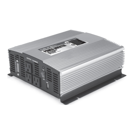
Summary of Contents for CEN-TECH Cen-tech 2000 watt continuous/4000 watt surge power inverter
- Page 2 table of Contents Safety ............2 Maintenance ..........9 Specifications ..........5 Parts List and Diagram ......11 Setup ............6 Warranty ............ 12 Operation ............ 8 WaRninG SYmBOlS anD DeFinitiOnS This is the safety alert symbol. It is used to alert you to potential personal injury hazards. Obey all safety messages that follow this symbol to avoid possible injury or death.
-
Page 3: Battery Precautions
1. DO nOt inStall thiS inveRteR intO a 7. Keep inverter dry and clean. Do not expose BuilDinG’S eleCtRiCal SYStem. this inverter to rain, snow, spray, bilge water or dust. is a vehicular accessory. it is not designed 8. Use cables that are thick enough. The more power to be safely used in a building’s electrical (amps) or the longer the cables, the thicker they system and has not been evaluated to meet... -
Page 4: Save These Instructions
4. Fuses must be replaced with fuses of 2. Maintain labels and nameplates on the the same type and rating only. Inverter. These carry important safety information. If unreadable or missing, contact Harbor Freight Tools for a replacement. Save theSe inStRuCtiOnS. Symbology Double Insulated Direct Current Supply... -
Page 5: Specifications
Specifications Input Voltage 12-15 VDC Output Voltage 115 V~, 60 Hz Continuous Power 2000 Watt Surge Power 4000 Watt Operating Conditions 32° - 104° F AC Receptacles Three 3-prong grounded polarized outlets Eight 30 Amp Internal Blade-type Fuses Fuse Type (professional replacement only) Minimum Battery Cable For a 6"... -
Page 6: Installation
installation Read the entiRe impORtant SaFetY inFORmatiOn section at the beginning of this manual including all text under subheadings therein before set up or use of this product. tO pRevent SeRiOuS inJuRY FROm aCCiDental OpeRatiOn: make sure that the power Switch is in the off-position and unplug the tool from its electrical outlet before performing any procedure in this section. -
Page 7: Functions
• Locate battery bank in a clean, well- c. Then connect all the negative ventilated area, away from ignition sources terminals to one another. and flammable materials. Batteries release d. Connect the negative and positive output cables explosive hydrogen gas while charging. to opposite ends of the bank. -
Page 8: Operating Instructions
Operating instructions Read the entiRe impORtant SaFetY inFORmatiOn section at the beginning of this manual including all text under subheadings therein before set up or use of this product. tool Set up tO pRevent SeRiOuS inJuRY FROm aCCiDental OpeRatiOn: make sure that all power Switches/triggers is in the off-position and unplug the tool from its electrical outlet before performing any procedure in this section. -
Page 9: Maintenance
maintenance and Servicing procedures not specifically explained in this manual must be performed only by a qualified technician. tO pRevent SeRiOuS inJuRY FROm aCCiDental OpeRatiOn: make sure that all loads are disconnected from the inverter, the power Switch is in the off-position and the cables are disconnected from power source before performing any procedure in this section. -
Page 10: Troubleshooting
troubleshooting problem possible Causes probable Solutions Inverter shuts off 1. Excessive load at output. 1. Reduce load to less than rated power. during use 2. Internal temperature 2. Let the Inverter cool down for at least 30 is too high. minutes. -
Page 11: Parts List And Diagram
parts list and Diagram part Description part Description Plastic Screw M3x12 Contral Panel LED 5.0 Fan 50x50x20 LED Cover Rear Panel Switch NegativeTerminal Cover Screw 2.8x8.0 Screw M4x8 AC Socket Positive Terminal Cover Front Panel Screw 2.8x8.0 Screw M3x6 Screw M4x6 PCB of Remote Bottom Plate PCB of Display... - Page 12 90 Day Warranty Harbor Freight Tools Co. makes every effort to assure that its products meet high quality and durability standards, and warrants to the original purchaser that this product is free from defects in materials and workmanship for the period of 90 days from the date of purchase.


Need help?
Do you have a question about the Cen-tech 2000 watt continuous/4000 watt surge power inverter and is the answer not in the manual?
Questions and answers