Table of Contents
Advertisement
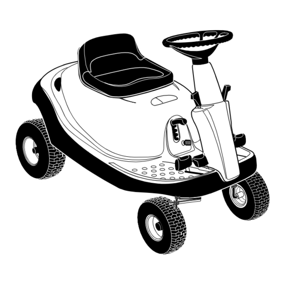
Operator's Manual
Riding Mower
Internal Bagging System
Model 1027
(13A-328-101)
IMPORTANT: Read safety rules and instructions carefully before operating equipment.
Warning:
This unit is equipped with an internal combustion engine and should not be used on or near any unimproved forest-
covered, brush-covered or grass-covered land unless the engine's exhaust system is equipped with a spark arrester meeting
applicable local or state laws (if any). If a spark arrester is used, it should be maintained in effective working order by the operator.
In the State of California the above is required by law (Section 4442 of the California Public Resources Code). Other states may have
similar laws. Federal laws apply on federal lands. A spark arrester for the muffler is available through your nearest engine authorized
service dealer or contact the service department, P.O. Box 368023 Cleveland, Ohio 44136-9722.
CUB CADET CORP. P.O. BOX 368023 CLEVELAND, OHIO 44136-9722
FORM NO. 770-10094B.fm
PRINTED IN U.S.A.
(12/99)
Advertisement
Table of Contents

Related Manuals for Cub Cadet 1027


Summary of Contents for Cub Cadet 1027
- Page 1 Federal laws apply on federal lands. A spark arrester for the muffler is available through your nearest engine authorized service dealer or contact the service department, P.O. Box 368023 Cleveland, Ohio 44136-9722. CUB CADET CORP. P.O. BOX 368023 CLEVELAND, OHIO 44136-9722 FORM NO. 770-10094B.fm PRINTED IN U.S.A.
-
Page 2: Table Of Contents
(Model Number) (Serial Number) Copy the model number here: Copy the serial number here: CUB CADET CORP. P.O. BOX 368023 CLEVELAND, OHIO 44136 CALLING CUSTOMER SUPPORT If you have difficulty assembling this product or have any questions regarding the controls, operation or maintenance of this unit, please call the Customer Dealer Referral Line. -
Page 3: Important Safe Operation Practices
SECTION 1: IMPORTANT SAFE OPERATION PRACTICES This symbol points out important safety instructions which, if not followed, could endanger the personal safety and/or property of yourself and others. Read and follow all instructions in this manual before attempting to operate your rider mower. Failure to comply with these instructions may result in personal injury. - Page 4 injury or death. All slopes require extra caution. If • Before and when backing, look behind and down you cannot back up the slope or if you feel uneasy for small children. on it, do not mow it. • Never carry children. They may fall off and be •...
- Page 5 • Grass catcher components are subject to wear, • Observe proper disposal laws and regulations. damage and deterioration, which could expose Improper disposal of fluids and materials can harm moving parts or allow objects to be thrown. For your the environment and the ecology. safety protection, frequently check components a.
-
Page 6: Slope Gauge
SECTION 2: SLOPE GUAGE USE THIS PAGE AS A GUIDE TO DETERMINE SLOPES WHERE YOU MAY NOT OPERATE RIDER SAFELY:... -
Page 7: Assembling Your Riding Mower
SECTION 3: UNPACKING & ASSEMBLING YOUR RIDER MOWER • Remove all screws and staples from crate. • Remove red and black insulation caps from battery • Holding the sides of the crate firmly, lift the top of terminals. See Figure 3 the crate up and keep it aside. - Page 8 • Pivot the hood assembly up and lower the cutting • To attach the mulching plug now to the unit, follow height adjustment lever to the lowest position. instructions on previous page to attach side- • Remove the two wing nuts (A and B in Figure 4 ) discharge chute to the deck.
-
Page 9: Know Your Riding Mower
SECTION 4: KNOW YOUR RIDER MOWER Compare the illustrations in Figure 8 with your rider mower to familiarize yourself with the location of various controls and adjustments. The operation of any rider mower can result in foreign objects being thrown into the operator’s eyes, causing severe eye damage. -
Page 10: Stopping Mower
Cutting Height Adjustment Lever • Before you move the shift lever to any of the positions, depress the brake pedal and stop the Use to raise and lower the cutting deck which unit. Keep your foot on the brake pedal. determines the cutting height. -
Page 11: Operating Your Riding Mower
SECTION 5: OPERATING YOUR RIDER MOWER Using Throttle/Choke Control • Turn the ignition key to the START position. As soon as the engine starts, let the key return to the The throttle/choke control is used to increase or ON position. decrease the speed of the engine.The FAST and the •... -
Page 12: Using The Mower
• Pivot the cover up. Pull up the grasscatcher bag • When mowing an area for the first time, watch out by the handle and take it to the proper disposal for objects lying on the grass. If you strike a foreign site. -
Page 13: Brake Pedal
SECTION 6: MAKING ADJUSTMENTS “Go” Pedal WARNING: Do not at any time make any adjustment to riding mower without first Adjustment to the "Go" pedal is made at the cable end. stopping engine and disconnecting spark See Figure 11 . plug wire. -
Page 14: Adjusting The Deck
Seat Position • If the belt is slipping when you depress the blade engagement pedal about 3/4”, loosen the two hex The seat position on the rider mower can be adjusted to nuts on the cable. See Figure 12. maximize the operator’s convenience. •... -
Page 15: Belt Replacement
• Completely loosen, but do not remove, the top hex • Thread the middle nut as far down as possible. nut out of the three hex nuts that hold the hex bolt • When desired adjustment is reached, retighten the and the ferrule on the deck hanger link assembly. -
Page 16: Fuse Replacement
• Using a 9/16” wrench, loosen the hex nut on the • Using a 9/16” socket, remove bolt, spacer and the idler pulley. See Figure 15. flat washer from the variable speed pulley. See • Remove belt from around deck pulley, idler pulley, Figure 16 . -
Page 17: Maintaining Your Riding Mower
SECTION 8: MAINTAINING YOUR RIDER MOWER General Recommendations when rotating at high speeds, may cause damage to the mower and/or cause personal injury. • Always observe safety rules when performing any • The blade can be tested for balance by balancing it maintenance. -
Page 18: Fuel Filter
Blade Assembly • The spark plug should be cleaned and the gap reset once a season. Spark plug replacement is • Lubricate blade assembly and deck spindle only recommended at the start of each mowing season. while reassembling the blade either after Check engine manual for correct plug type and gap sharpening or replacement. -
Page 19: Off-Season Storage
SECTION 9: OFF-SEASON STORAGE If the machine is to be inoperative for a period longer NEVER store battery without a full charge. Recharge battery before returning to service or than 30 days, prepare for storage as follows. every two months, whichever occurs first. Rider Mower •... -
Page 20: Troubleshooting
SECTION 10: TROUBLE-SHOOTING Trouble Possible Cause Remedial Action Excessive vibration Bent or damaged blade Stop engine immediately. Check all pulleys, blade adapters, keys and bolts for tightness and spindle damage. Tighten or replace any damaged parts. Bent blade. Stop engine immediately. Replace damaged blade. - Page 21 Dipstick not seated or broken Replace defective part. Engine loses crankcase vacuum Engine breather defective. Replace. For repairs beyond those listed in the Trouble-Shooting chart above, please contact an authorized service dealer or call Cub Cadet Customer Service at 1- (800)-528-1009.
-
Page 22: Parts List
SECTION 11: PARTS LIST FOR MODEL 1027 Ref. Part No. Description 731-2295 Steering Wheel 731-2296 Steering Wheel Insert Ref. Part No. Description 731-1919 Steering Column: Black 731-1857 Control Knob 712-0142 Hex Nut 8-32 710-3217 Pan Head Machine Screw #8-32 710-0599 Hex Screw TT 1/4-20 x .50”... - Page 23 Model 1027...
- Page 24 Model 1027 Ref. Ref. Part No. Description Part No. Description 731-0511 Trim Strip 17962 Switch Plate 735-0265A Floor Pad: LH 650-0007 Steering Tube Assembly 735-0266A Floor Pad: RH 683-0033A Steering Support Bracket 736-0105 Bell Washer 683-0178A Front Axle Assembly: RH...
- Page 25 Model 1027...
- Page 26 Model 1027 Ref. Ref. Part No. Description Part No. Description 683-0155 Brake Pedal Assembly 736-0329 Lock Washer 683-0156 Variable Pedal Assembly 736-0608 Spring Washer 683-0275 Deck Pedal Assembly 736-3000 Flat Washer 683-0161 Shift Cam Assembly 736-3019 Flat Washer .531 X 1.062 X .134 710-1017 Ab Screw 1/4-14 X .625...
-
Page 27: Parts Diagram
Model 1027 13 23 Ref. Part No. Description 683-0152 Pivot Link Assembly 683-0194 Lift Arm Assembly 710-0376 Hex Screw 5/16-18 X 1.00 Gr.5 710-3230 Hex Bolt 1/2-13 X 2.75 Gr.5 Special Ref. Part No. Description 711-0332 Lift Bracket Pin 736-0119... - Page 28 Model 1027 Ref. Part No. Description 629-0865 Harness Assembly Adapter 710-1208 Hex TT Screw 5/16-18 x 3.50 710-0227 Hex Washer Head Self-Tap.Scew 710-0805 Hex Screw 5/16-18 x 1.5 Gr. 5 710-0642 Thd. Forming Scr. 1/4-20x .75 712-3010 Hex Nut 5/16-18...
- Page 29 Model 1027 Ref. Part No. Description 683-0147 Idler Bracket Assembly 710-0191 Hex Screw 3/8-24 x 1.25 710-0314 Hex Screw 7/16-20 x 1.0” 710-0902 Cap Screw 3/8-24 x 3.75 710-1611 Pan Head TL Screw 5/16-18 x .75 710-3096 Hex Screw 3/8-16 x 2.0 Special...
- Page 30 Model 1027 Ref. Part No. Description 783-0605 Deck Stabilizing Bracket 783-0564A Front Frame: Upper Ref. 783-0811- Steering Gear Cover Part No. Description 0716 737-3007 Grease 683-0264 Front Channel Assembly 725-0157 Cable Tie 783-0554 Cam Bracket 714-0470 Hairpin Clip 783-0414A Frame Rail: Rear...
- Page 31 Model 1027...
- Page 32 Model 1027 Ref. Ref. Part No. Description Part No. Description 683-0149B Frame Assembly 731-1945 Engine Duct 683-0190A Frame Rail Support: RH 732-3080 Compression Spring 683-0191A Frame Rail Support: LH 735-0273 Rubber Washer 683-0192 Muffler Pipe Extension 736-0119 Lock Washer 710-0148 Hex Fl.
- Page 33 Model 1027 Ref. Part No. Description Ref. Part No. Description 710-0599 TT Screw 1/4-20 x 0.5 783-0446 Plate: Hood 710-0870 TT Screw 3/8-16 x 0.62 783-0447 Hood Bracket 710-1017 Torx AB Screw 1/4-14 x 0.625 783-0448 Hood Bracket: Reinforcement 720-0238...
- Page 34 Model 1027 Ref. Part No. Description 618-0232 Differential Assembly: Single Speed 618-0248 Drive Shaft assembly: LH Brake 618-0072B Upper Housing Assembly 611-0114 Detent Shaft Assembly 661-0006 Brake Yoke Assembly: LH 710-1206 Hex Washer Hd. TT Screw 1/4-20 x 2.37 Gr.5 710-1325 Hex Washer Hd.
- Page 35 Model 1027 Ref. Part No. Description 710-0650 Self-Tapp. Screw 5/16-18 x .75 710-0672 Hex Cap Scr. 5/16-24 x 1.25 710-0932 Carriage Screw 710-1611 Torx Screw 5/16-18 x .75 712-0241 Hex Nut 3/8-24 712-0397 Wing Nut With Bell Washer 712-0417A Flange Nut 5/8-18...
- Page 36 Model 1027 Ref. Part No. Description 631-0060 Flow Indicator Assembly 631-0080 Grass Bag Assembly 710-0166 Machine Screw 1/4-20 x 1.0 710-0286 Machine Screw 1/4-20 x 0.5” 710-0456 Hex Screw #10-16 x 0.5” 710-0564 Hex Screw 1/4-20 x 2.75” 710-0642 Self-Tapping Screw 1/4-20 x 0.75”...
- Page 37 Model 1027 Ref. Part No. Description 629-0945 Harness Assembly w/o relays 725-0267 Ignition Switch: 5 Pin 725-1345 Ignition Key (not shown) 725-1426 Solenoid: 12 V. 100 amp. 725-1462 Seat Switch 725-1643 Spring Switch 725-1657A Interlock Switch 725-1381 Fuse: 20 amp.
- Page 38 Your Notes Date Comments...
- Page 39 Your Notes Date Comments...
-
Page 40: Cleveland, Ohio
There is no other express warranty. How to obtain service Contact your authorized Cub Cadet servicing dealer who sold you your Cadet equipment. If this dealer is not available, see the Consumer Yellow Pages under “lawn mowers” for the name of a dealer near you.
Need help?
Do you have a question about the 1027 and is the answer not in the manual?
Questions and answers