Table of Contents
Advertisement
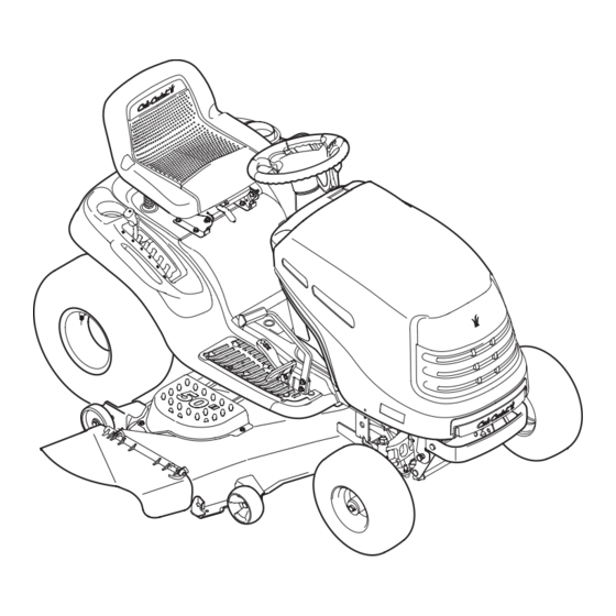
Operator's Manual
S
ERIES 1000
Hydrostatic Lawn Tractor
Model LT1024
IMPORTANT: READ SAFETY RULES AND INSTRUCTIONS CAREFULLY
Warning:
This unit is equipped with an internal combustion engine and should not be used on or near any unimproved forest-covered, brush-
covered or grass-covered land unless the engine's exhaust system is equipped with a spark arrester meeting applicable local or state laws (if
any). If a spark arrester is used, it should be maintained in effective working order by the operator. In the State of California the above is required
by law (Section 4442 of the California Public Resources Code). Other states may have similar laws. Federal laws apply on federal lands. A spark
arrester for the muffler is available through your Cub Cadet dealer or contact the service department, P.O. Box 361131 Cleveland, Ohio 44136-
0019.
CUB CADET LLC, P.O. BOX 361131 CLEVELAND, OHIO 44136-0019
FORM NO. 769-01021A.fm
PRINTED IN U.S.A.
(6/17/2004)
Advertisement
Table of Contents

Related Manuals for Cub Cadet LT1024


Summary of Contents for Cub Cadet LT1024
- Page 1 Operator’s Manual ERIES 1000 Hydrostatic Lawn Tractor Model LT1024 IMPORTANT: READ SAFETY RULES AND INSTRUCTIONS CAREFULLY Warning: This unit is equipped with an internal combustion engine and should not be used on or near any unimproved forest-covered, brush- covered or grass-covered land unless the engine’s exhaust system is equipped with a spark arrester meeting applicable local or state laws (if any).
-
Page 2: Finding Model Number
Content Important Safe Operation Practices Slope Guage Tractor Set-up Know Your Lawn Tractor Operating Your Lawn Tractor Making Adjustments Maintaining Your Lawn Tractor This Operator’s Manual is an important part of your new lawn tractor. It will help you assemble, prepare and maintain the unit for best performance. -
Page 3: Section 1: Important Safe Operation Practices
SECTION 1: IMPORTANT SAFE OPERATION PRACTICES WARNING: This symbol points out important safety instructions which, if not followed, could endanger the personal safety and/or property of yourself and others. Read and follow all instructions in this manual before attempting to operate this machine. Failure to comply with these instructions may result in personal injury. -
Page 4: Slope Operation
unload properly. 23. Muffler and engine become hot and can cause a burn. Do not touch. 24. Check overhead clearances carefully before driving under low hanging tree branches, wires, door openings etc., where the operator may be struck or pulled from the unit, which could result in serious injury. -
Page 5: Safe Handling Of Gasoline
d. Never carry children, even with the blade(s) shut off. They may fall off and be seriously injured or interfere with safe machine operation. e. Use extreme care when approaching blind corners, doorways, shrubs, trees or other objects that may block your vision of a child who may run into the machine. - Page 6 6. Mower blades are sharp. Wrap the blade or wear gloves, and use extra caution when servicing them. 7. Keep all nuts, bolts, and screws tight to be sure the equipment is in safe working condition. 8. Never tamper with the safety interlock system or other safety devices.
-
Page 7: Slope Gauge
SLOPE GAUGE... -
Page 8: Safety Labels
TO REDUCE THE RISK OF INJURY, DO NOT OPERATE UNLESS DISCHARGE COVER OR GRASS CATCHER IS IN ITS PROPER PLACE. IF DAMAGED, REPLACE IMMEDIATELY. S30018 3.15 DANGER KEEP HANDS AND FEET AWAY. DO NOT OPERATE MOWER UNLESS CHUTE DEFLECTOR OR ENTIRE GRASS CATCHER IS IN ITS PROPER PLACE. -
Page 9: Section 3: Know Your Lawn Tractor
SECTION 3: KNOW YOUR LAWN TRACTOR Systems Indicator Monitor/Hour Meter H Throttle Control Lever Choke Control Parking Brake Lever Fuel Tank Cap Seat Adjustment Lever G PTO (Power Take-off) Knob NOTE: Any reference in this manual to the RIGHT or LEFT side of the tractor is observed from operator’s position. BATTERY OIL PRESSURE PTO / BLADE ENGAGE... -
Page 10: Throttle Control Lever
Throttle Control Lever The throttle control lever is located on the left side of the tractor’s dash panel. This lever controls the speed of the engine. When set in a given position, the throttle will maintain a uniform engine speed. See Figure 2. Fast Position Slow... -
Page 11: Cruise Control Lever
Hour Meter Located in the center of the tractor’s console, the hour meter operates whenever the engine is running and records the actual hours of tractor operation. See Figure 4. BATTERY HOURS 1/10 PTO / BLADE ENGAGE Figure 4 System Indicator Lights Your tractor is equipped with four indicator lights in the center of its dash panel. -
Page 12: Seat Adjustment Lever
Seat Adjustment Lever To adjust the seat forward or backward, slide the seat adjustment lever to the left and reposition the seat to the desired position. Once a comfortable position is found, release the seat adjustment lever to lock the seat in place. -
Page 13: Engaging The Parking Brake
Shoulder Screw Lock Nut Shoulder Screw Figure 5 • If the gauge wheels have excessive clearance with the surface below, lower the wheels to the index hole that provides the approximate 1/2" clearance as described above. Refer to Leveling the Deck on page 16 of this manual for more detailed instructions regarding various deck adjustments. -
Page 14: Driving On Slopes
• To travel FORWARD, slowly depress the upper portion of the drive pedal forward until the desired speed is achieved. See Figure 6. Figure 6 • To travel in REVERSE, check that the area behind is clear then slowly depress the lower portion of the drive pedal with the ball of your foot (NOT your heel) until the desired speed is achieved. -
Page 15: Moving The Tractor Manually
Moving The Tractor Manually Your tractor’s transmission is equipped with a hydrostatic relief valve for occasions when it is necessary to move the tractor manually. Opening this valve permits the fluid in the transmission to bypass its normal route, allowing the rear tires to "freewheel." To open the hydrostatic relief valve, proceed as follows: •... -
Page 16: Leveling The Deck
SECTION 5: MAKING ADJUSTMENTS WARNING: Never attempt to make any adjustments while the engine is running, except where specified in the operator’s manual. Leveling the Deck NOTE: Check the tractor’s tire pressure before performing any deck leveling adjustments. Refer to Tires on page 19 for information regarding tire pressure. -
Page 17: Parking Brake Adjustment
Parking Brake Adjustment WARNING: Never attempt to adjust the brakes while the engine is running. Always disengage PTO, stop engine and remove key to prevent unintended starting. If the tractor does not come to a complete stop when the brake pedal is completely depressed, or if the tractor’s rear wheels can roll with the parking brake applied, the brake is in need of adjustment. -
Page 18: Maintaining Engine
SECTION 6: MAINTAINING YOUR LAWN TRACTOR NOTE: Refer to Maintenance Chart on page 24 for a reference of recommended maintenance intervals. WARNING: Before maintenance or repairs, disengage PTO, set parking brake, stop engine and remove key to prevent unintended starting. Engine Refer to the Briggs &... -
Page 19: Cutting Blades
Deck Spindles and Deck Idler Bracket Grease fittings can be found on the top of each deck spindle shaft as well as on the idler bracket. See Figure 14. Lubricate with 251H EP grease or an equivalent No. 2 multi-purpose lithium grease. Grease Fitting Figure 14 SECTION 7: SERVICE... - Page 20 • Place a block of wood between the deck housing baffle and the cutting blade to act as a stabilizer. See Figure 16. Hex Flange Nut Wood Block Spindle Assembly Figure 16 • Use a 1-1/8" wrench to remove the hex flange nut that secures the blade to the spindle assembly.
-
Page 21: Changing The Deck/Pto Belt
Fuse A fuse is installed in your tractor’s wiring harness to protect the tractor’s electrical system from damage caused by excessive amperage. If the electrical system does not function, or your tractor’s engine will not crank, first check to be certain that the fuse has not blown. -
Page 22: Changing The Transmission Drive Belt
Electric PTO Clutch Pivoting Idler Pulley Right Hand Pulley (beneath belt guard) • Grasp the ratchet’s handle and pivot it toward the tractor’s right side to relieve tension on the belt. • With belt tension relieved, carefully remove the belt from around theleft-hand spindle pulley. WARNING: Avoid the possiblity of a pinching injury. -
Page 23: Hydrostatic Transmission
• Pivot the double-idler bracket forward slightly before removing the idler extension spring from the stud and the double-idler bracket itself. Do NOT discard the spring. • Roll the drive belt out from around both the v-idler pulley and the flat idler pulley found on the double- idler bracket. -
Page 24: Section 8: Off-Season Storage
SECTION 8: OFF-SEASON STORAGE Clean and lubricate the tractor as instructed in Section 7: MAINTAINING YOUR LAWN TRACTOR on page 18 of this manual before storing for an extended period. Engine If the engine will be out of service for two months or more, use the following storage procedure: •... -
Page 25: Section 11: Attachments & Accessories
Uneven tire pressure. SECTION 11: ATTACHMENTS & ACCESSORIES The following attachments and accessories are compatible for Model LT1024. See your Cub Cadet dealer or the retailer from which you purchased your tractor for information regarding price and availability.Model LT1024 is NOT designed for use with any type of ground-engaging attachments . -
Page 26: Section 12: Specifications
SECTION 12: SPECIFICATIONS Capacities Fuel Tank Crankcase (approximately) Hydrostatic Transmission Make and Model Gear Ratio Forward Speed Reverse Speed Engine (Air-cooled, 4-cycle) Make, Model & Type Cylinders Bore Stroke Displacement Maximum Torque @2400 RPM Compression Ratio Engine Speed (governed) Low Speed High Speed (no load) Spark Plug Gap Armature Air Gap... -
Page 27: Cub Cadet Llc
MANUFACTURER’S ONE YEAR LIMITED WARRANTY The limited warranty set forth below is given by CUB CADET LLC (“CUB CADET”) with respect to new merchandise pur- chased and used in the United States, its possessions and territories. CUB CADET warrants this product against defects in mate- rial and workmanship for a period of one (1) year for com- mercial users, commencing on the date of original purchase and will, at its option, repair or replace, free of charge, any... - Page 28 MANUFACTURER’S LIMITED WARRANTY The limited warranty set forth below is given by CUB CADET LLC (“CUB CADET”) with respect to new merchandise pur- chased and used in the United States, its possessions and territories. CUB CADET warrants this product against defects in material and workmanship for a period of two (2) years for residential users, (one (1) year for commercial users), commencing on the date of original purchase and will, at its option, repair or...
Need help?
Do you have a question about the LT1024 and is the answer not in the manual?
Questions and answers
Transmission running very slow and has trouble going up inclines is there anyway to enhance the transmission performance or does it need to be replaced?
To enhance the transmission performance of a Cub Cadet LT1024, consider replacing worn or faulty parts such as the transmission pulley. A replacement transmission pulley designed for the LT1024 can improve performance and reliability. These parts are made with durable materials for long-lasting use and offer a precise fit for easy installation. If performance issues persist after replacing components like the pulley, a full transmission replacement may be necessary.
This answer is automatically generated