Table of Contents
Advertisement
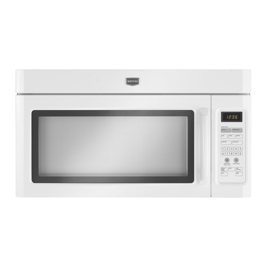
MICROWAVE
HOOD
COMBINATION
INSTALLATION
INSTRUCTIONS
This product is suitable for use above electric or gas cooking products up to and including 36" (91.4 cm) wide. See "Installation
Requirements" section for further notes.
These installation instructions cover different models. The appearance of your particular model may differ slightly from the illustration in
these installation instructions.
Table of Contents
MICROWAVE HOOD COMBINATION SAFETY.............................. 1
INSTALLATION REQUIREMENTS................................................... 2
Tools and Parts............................................................................... 2
Remove Cardboard Template........................................................ 2
Location Requirements................................................................... 2
Product Dimensions ....................................................................... 3
Electrical Requirements.................................................................. 3
INSTALLATION INSTRUCTIONS..................................................... 4
Remove Mounting Plate................................................................. 4
Rotate Blower Motor....................................................................... 4
Locate Wall Stud(s)......................................................................... 6
Mark RearWall................................................................................ 7
Drill Holes in RearWall.................................................................... 7
Attach Mounting Plate to Wall........................................................ 8
Prepare Upper Cabinet................................................................... 8
Install DamperAssembly ................................................................ 9
Install the Microwave Oven ............................................................ 9
Complete Installation.................................................................... 10
VENTING DESIGN SPECIFICATIONS............................................ 1 1
ASSISTANCE ................................................................................... 12
Replacement Parts ....................................................................... 12
Accessories................................................................................... 12
MICROWAVE
HOOD
COMBINATION
SAFETY
Your safety and the safety of others are very important.
We have provided many important safety messages in this manual and on your appliance. Always read and obey all safety
messages.
This is the safety alert symbol.
This symbol alerts you to potential hazards that can kill or hurt you and others.
All safety messages will follow the safety alert symbol and either the word "DANGER" or "WARNING."
These words mean:
You can be killed or seriously injured if you don't immediately
follow
instructions.
You can be killed or seriously injured if you don't follow
instructions.
All safety messages will tell you what the potential hazard is, tell you how to reduce the chance of injury, and tell you what can
happen if the instructions are not followed.
W10344702B
Advertisement
Table of Contents


Need help?
Do you have a question about the MMV1164WB5 and is the answer not in the manual?
Questions and answers