Table of Contents
Advertisement
Available languages
Available languages
INSTALLATION INSTRUCTIONS
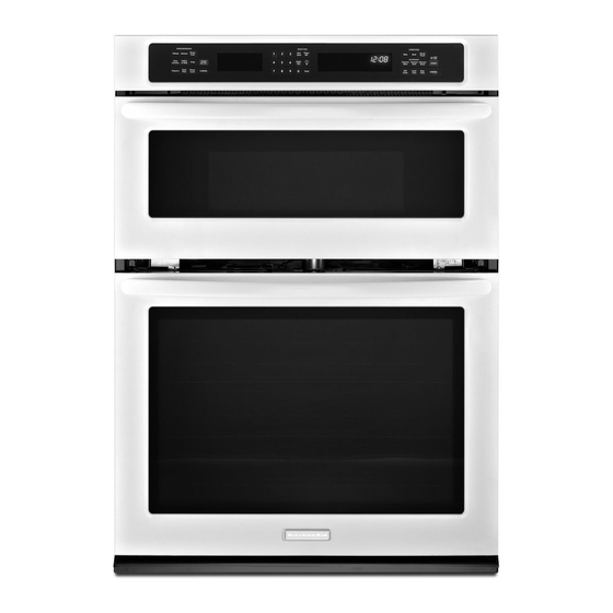
27" (68.6 CM) AND 30" (76.2 CM) ELECTRICBUILT-IN
MICROWAVE/OVEN COMBINATION
INSTRUCTIONS D'INSTALLATION
FOURCONVENTIONNEL ETFOURA MICRO-ONDES
f:LECTRIQUES, COMBINf:S ETENCASTRf:S
DE 27" (68,6 CM) ET30" (76,2 CM)
Tableof Contents/Table des mati@res
BUILT-IN MICROWAVE/OVEN
COMBINATION
SAFETY ................................................................
1
INSTALLATION REQUIREMENTS
................................................
2
Tools and Parts ............................................................................
2
Built-In Microwave/Oven
Combination
Location Requirements ................................................................
2
Electrical Requirements ...............................................................
4
INSTALLATION
INSTRUCTIONS ..................................................
5
Prepare Built-In Microwave/Oven
Combination .......................... 5
Remove Oven Door ......................................................................
5
Make Electrical Connection .........................................................
5
Install Oven ...................................................................................
7
Complete Installation ...................................................................
8
SI_CURITI_ DU FOUR .& MICRO-ONDES
ET DU FOUR
CONVENTIONNEL
COMBINI_S ET ENCASTRI_S ........................ 9
EXIGENCES D'INSTALLATION ...................................................
10
Outils et pieces ...........................................................................
10
Exigences d'emplacement
de I'ensemble four &
micro-ondes et four conventionnel encastres ........................... 10
Specifications
electriques ..........................................................
12
INSTRUCTIONS
D'INSTALLATION .............................................
13
Preparation de I'ensemble des fours encastres
(micro-ondes/conventionnel)
.....................................................
13
Depose de la porte du four ........................................................
13
Raccordement electrique ...........................................................
13
Installation du four ......................................................................
15
Achever I'installation ..................................................................
16
BUILT-IN MICROWAVE/OVEN COMBINATION SAFETY
Your safety and the safety of others are very important.
We have provided many important safety messages in this manual and on your appliance. Always read and obey all safety
messages.
This is the safety alert symbol.
This symbol alerts you to potential hazards that can kill or hurt you and others.
All safety messages will follow the safety alert symbol and either the word "DANGER" or "WARNING."
These words mean:
You can be killed or seriously injured if you don't immediately
follow
instructions.
You can be killed or seriously injured if you don't follow
instructions.
All safety messages will tell you what the potential hazard is, tell you how to reduce the chance of injury, and tell you what can
happen if the instructions are not followed.
iMPORTANT:
Save for local electrical inspector's use.
iMPORTANT
:
A,conserver pour consultation par I'inspecteur local des installations 61ectriques.
W10351241A
Advertisement
Table of Contents

Related Manuals for KitchenAid KEMS309BSP00


Summary of Contents for KitchenAid KEMS309BSP00
- Page 1 INSTALLATION INSTRUCTIONS 27" (68.6 CM) AND 30" (76.2 CM) ELECTRICBUILT-IN MICROWAVE/OVEN COMBINATION INSTRUCTIONS D'INSTALLATION FOURCONVENTIONNEL ETFOURA MICRO-ONDES f:LECTRIQUES, COMBINf:S ETENCASTRf:S DE 27" (68,6 CM) ET30" (76,2 CM) Tableof Contents/Table des mati@res SI_CURITI_ DU FOUR .& MICRO-ONDES ET DU FOUR BUILT-IN MICROWAVE/OVEN CONVENTIONNEL COMBINI_S ET ENCASTRI_S ......
- Page 2 INSTALLATION REQUIREMENTS Gather the required tools and parts before starting installation. Read and follow the instructions provided with any tools listed IMPORTANT: Observe all governing codes and ordinances. here. • Cabinet opening dimensions that are shown must be used. Given dimensions provide minimum clearance with oven. Tools needed •...
- Page 3 Cabinet Dimensions Product Dimensions 27" (68.6 cm) and 30" (76.2 cm) Ovens 27" (68.6 cm) and 30" (76.2 cm) Ovens 27" (68.6 cm) models 30" (76.2 cm) models A. 27" (68.6 cm) min. cabinet A. 30" (76.2 cm) min. cabinet width width B.
- Page 4 Ifcodes permit and a separate ground w ire isused, i tis • Do not cut the conduit. The length of conduit provided is for recommended thataqualified electrical installer determine that serviceability of the oven. theground p ath andwire gauge areinaccordance withlocal •...
- Page 5 INSTALLATION INSTRUCTIONS Co_,_' _÷c o_, 1. Decide on the final location for the oven. Locate existing wiring to avoid drilling into or severing wiring during installation. Excessive Weight Hazard Electrical Shock Hazard Use two or more people to move and install oven. Disconnect power before servicing.
- Page 6 Electrical Connection Options Chart 3-Wire Cable from Home Power Supply - U.S. Only If your home has: Go to section: IMPORTANT: Use the 3-wire cable from home power supply 4-wire 4-wire Cable from Home where local codes permit a 3-wire connection. Power Supply 3-wire 3-wire Cable from Home...
- Page 7 Using 2 or more people, lift oven partially into cabinet cutout. Securely fasten oven to cabinet using the #8-14 x 1" screws Use the oven opening as an area to grip. provided. Insert the screws through hole in the grommet. Do not overtighten screws.
- Page 8 1. Check that all parts are now installed. If there is an extra part, Check Operation of Microwave Oven go back through the steps to see which step was skipped. 1. Fill a microwave-safe container with 1 cup (250 mL) of water and place container inside microwave oven.
- Page 9 SI_CURITI_ DU FOUR,_ MICRO-QNDES ETDU FQUR CONVENTIONNELCOMBINES ETENCASTRES Votre securite et celle des autres est tres importante. Nous donnons de nombreux messages de s_curit_ importants dans ce manuel et sur votre appareil m_nager. Assurez-vous toujours lire tous les messages de s_curit_ et de vous y conformer. Ce symbole d'alerte de s_curit_ vous signale les dangers potentiels de d_c_s et de blessures graves &...
- Page 10 EXIGENCESD'INSTALLATION o=,>,, ..IOU[ a .... _,,, .... o ,,,.= o..,, ....Rassembler les outils et pieces necessaires avant d'entreprendre I'installation. Lire et observer les instructions fournies avec chacun des outils de la liste ci-dessous. IMPORTANT • Observer les dispositions de tousles codes et reglements en vigueur.
- Page 11 Dimensions du placard Dimensions du produit Fours de 27" (68,6 cm) et 30" (76,2 cm) Fours de 27" (68,6 cm) et 30" (76,2 cm) Modeles de 27" (68,6 cm) Modeles de 30" (76,2 cm) A. Largeur du placard A. Largeur du placard 27"...
- Page 12 Si on utilise un conducteur distinct de liaison & la terre Iorsque les Ne pas couper le conduit. La Iongueur du conduit fournie est destinee & faciliter I'entretien du four. codes le permettent, il est recommande qu'un electricien qualifie verifie que la liaison & la terre et le calibre pour ills sont •...
- Page 13 INSTRUCTIONS D'INSTALLATION ; emen:f @ec 1. Choisir I'emplacement final pour I'installation du four. Reperer le c&blage existant pour eviter de le percer ou de I'endommager Iors de I'installation. Risque du poids excessif Utiliser deux ou plus de personnes pour d_placer Risque de choc _lectrique installer le four.
- Page 14 5. Acheminer le conduit de c&ble flexible depuis le four jusqu'au 3. Detorsader le conducteur blanc du conducteur vert (ou nu) de boitier de connexion - utiliser un connecteur de conduit liaison & la terre provenant du four. (homologation UL ou CSA). 4.
- Page 15 II]SlI_IIIGIOFI CRJ o_J A I'aide de deux personnes ou plus, soulever le four pour 5. Fixer solidement le four au placard & I'aide des vis n° 8-14 x 1" fournies. Inserer les vis & travers les trous des I'introduire partiellement dans I'ouverture d'installation dans le placard;...
- Page 16 V_rification du fonctionnement du four & micro-ondes 1. Verifier que toutes les pieces sont maintenant installees. S'il reste une piece, passer en revue les differentes etapes pour 1. Remplir un contenant adapte aux micro-ondes avec 1 tasse decouvrir laquelle aurait et6 oubliee. (250 mL) d'eau et placer le contenant dans le four a micro- ondes.
Need help?
Do you have a question about the KEMS309BSP00 and is the answer not in the manual?
Questions and answers