
Related Manuals for DRS Technologies Tamarisk 320


Summary of Contents for DRS Technologies Tamarisk 320
- Page 1 Tamarisk ® 17 μm 320x240 Long Wave Infrared Camera User Manual Document No: 1012593 Revision: D...
- Page 2 ©Copyright 2012, DRS TECHNOLOGIES, Inc. - All rights reserved. 13532 N. Central Expressway Dallas, TX 75243 877.377.4783 www.drsinfrared.com All rights reserved. The contents of this document may not be reproduced in whole or in parts without the written consent of the copyright owner. NOTICE ALL STATEMENTS, INFORMATION, AND RECOMMENDATIONS IN THIS MANUAL ARE BELIEVED TO BE ACCURATE BUT ARE PRESENTED WITHOUT WARRANTY OF ANY KIND.
-
Page 3: Table Of Contents
® Tamarisk User Manual A BL E OF ON T E N T S Table of Contents ........................i Acronyms and Abbreviations ....................i Reference Documentation ......................ii Safety Instructions ........................iii Notifications: Caution, Warning and Note ................... iii System Description ......................5 Introduction ........................ - Page 4 ® Tamarisk User Manual DRS Camera Control Software ..................37 DRS Camera Control Software Overview ............... 37 10 Contact Information ....................... 38...
-
Page 5: Acronyms And Abbreviations
® Tamarisk User Manual C R ON YM S AN D B BR E VI AT I ON S Abbreviation Description Abbreviation Description °C Celsius millimeter °F Fahrenheit milliseconds automatic gain control Most Significant Bit bad pixel replacement Maximum Transfer Unit circuit card assembly MWIR Mid-wave infrared... -
Page 6: Reference Documentation
® Tamarisk User Manual EF E R EN C E OC U M EN T AT I ON The following documents form part of this specification. In the event of a conflict between documents referenced herein and the contents of this specification, the contents of this specification shall be considered a superseding requirement. -
Page 7: Safety Instructions
® Tamarisk User Manual AF ET Y N ST R U C T I ON S NOTIFICATIONS: CAUTION, WARNING AND NOTE Throughout this manual, notifications are used to alert the user’s to potential risks and to minimize the potential for personal injury and or damage to the product. When a notification is present, it is important that the user review and understand all statements related to the notification before proceeding. -
Page 9: System Description
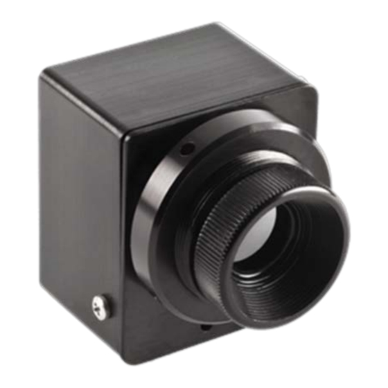
® Tamarisk User Manual Y S T E M E S C R I P T I O N 1.1 INTRODUCTION ® The Tamarisk is a VOx based long-wave infrared (LWIR) video camera built around DRS’s 17 μm pixel pitch 320X240 microbolometer detector and is sensitive to thermal radiation emissions ®... - Page 10 ® Tamarisk User Manual connector. Advantages of the BASE configuration are parallel digital video output, reduced size, weight and power requirements (see Appendix A for details). The BASE cofiguration is pictured in Figure 2 below. It is comprised of an optical lens asembly or OLA, (the OLA includes a lens, lens mount with integrated camera frame or chassis and a retaining ring);...
-
Page 11: Quick Reference Specification Table
® Tamarisk User Manual 1.3 QUICK REFERENCE SPECIFICATION TABLE Table 1: Tamarisk®320 Product Specifications Table Sensor Sensor Type Uncooled VOx Microbolometer Array Format 320x240 Pixel Pitch 17 µm Spectral Band 8 - 14 µm Sensitivity (NEdT) @ f/1.0 and 23C <... -
Page 12: Range Performance
® Tamarisk User Manual 1.4 RANGE PERFORMANCE Typical detection, recognition and identification range performance has been modeled for multiple ® available lens solutions using NVTHERM IP 2009 See Figure 4: Tamarisk Range Data. Tamarisk Range Data ® Man Identification 40° HFOV 7.5mm Man Recognition f/1.2... -
Page 13: Unpacking And Handling
® Tamarisk User Manual 1.5 UNPACKING AND HANDLING In this section, a typical packaging solution is presented along with steps for properly unpacking the ® Tamarisk product. See Table 2. WARNING DEVICE SENSITIVE TO ELECTROSTATIC DISCHARGE Electronics are sensitive to electrostatic discharge. Please follow appropriate ESD procedures when handling the open electronics board sets. - Page 14 ® Tamarisk User Manual Step # Steps View Open shipping container by breaking the seal and lifting the cardboard lid – a recess or notch has been cut into the box front to ease this process Remove top layer of protective foam or padding and review contents of the package to ensure all components are present.
-
Page 15: Theory Of Operation
® Tamarisk User Manual H E O R Y O F P E R A T I O N 2.1 INFRARED WAVES AND RADIATION Infrared radiation or infrared waves are electromagnetic waves with frequencies ranging from ~ 0.4 to 400 Terrahertz. This corresponds to a band on the electromagnetic spectrum just below (infra) red visible light. -
Page 16: Thermal Imaging
® Tamarisk User Manual and do not need to be energized or powered to work, for this reason bolometers are often referred to as passive detectors. Microbolometers, so called for the miniature size of the individual sensing elements, were introduced by Honeywell Corporation in the late 1970s and rely on intrinsic material properties that are sensitive to IR radiation. -
Page 17: Anatomy Of A Tamarisk ® 320
® Tamarisk User Manual Figure 7: Patent No. US 7,622,717 “Pixel Structure Having an Umbrella Type Absorber with One or More Recesses or Channels Sized to Increase Radiation Absorption.” This patent was filed on December 3, 2007 and granted on November 24, 2009. - Page 18 ® Tamarisk User Manual 2.4.1 Lens Lens material and optical designs have been optimized for the transmission of LWIR wavelengths between 8 -14µm and to utilize the full field of the FPA. If one of the available lens solutions does not meet the need for a particular application, a custom optic can be mated to a lens-less thermal imaging module to produce a custom solution - subsequent calibration may be necessary to optimize performance.
- Page 19 ® Tamarisk User Manual The Shutter is normally open allowing scene IR energy through to the sensor. The shutter closes briefly when performing a one-point calibration. A “clicking” sound can be heard and is typical under normal operation. The shutter can be controlled via an external command. 2.4.4 Sensor and Bias Board The sensor/FPA is mated directly to the Bias board.
-
Page 20: Set-Up And Operation
® Tamarisk User Manual U P A N D P E R A T I O N 3.1 MOUNTING ® The Tamarisk was designed as an OEM core with the versatility to be integrated into a wide ® range of applications. When embedding or mounting the Tamarisk it is important to provide proper heat strapping to maintain iso thermal performance as well as maintain an IP67 seal in applications requiring as much. -
Page 21: Power Connections And Sequence
® Tamarisk User Manual ® camera. Detailed power specifications and electrical pin-outs can be found in the Tamarisk Electrical Interface Control Document, P/N 1012820. CAUTION Operating the camera at voltage levels outside the specified range may result in permanent damage to the unit and void the product warranty. 3.3 POWER CONNECTIONS AND SEQUENCE Input power and camera control occurs through a single connector interface. -
Page 22: Electrical Interfaces
® Tamarisk User Manual Within two (2) seconds of power-up, it is normal to hear a “clicking” sound – indicative of a shutter event and the execution of a non-uniformity correction (NUC) or “one-point” (1-pt). Embedded software monitors pixel behavior within the FPA. As the camera’s internal electronics heat-up, the FPA temperature may also rise resulting in a shift in pixel output values. -
Page 23: Camera Controls
® Tamarisk User Manual A M E R A O N T R O L S 4.1 CAMERA FUNCTIONS AND IMAGE OPTIMIZATION OVERVIEW There are several camera functions for optimizing perormance and image quality. These functions are controlled via serial commands or through DRS’s camera control software GUI, Table 3 provides an overview of available camera functions and image/video adjustments. - Page 24 ® Tamarisk User Manual Item Description Function standard Sets analog video output to the Phase Alternating Line (B,D,G,H,I,N) standards Sets both the parallel digital video data and Camera Link 8-bit Digital Out video data output to display 8 bits Sets both the parallel digital video data and Camera Link Digital Mode 14-bit Digital Out digital video data output to display 14 bits...
-
Page 25: Maintenance And Routine Care
® Tamarisk User Manual A I N T E N A N C E A N D O U T I N E A R E 5.1 MAINTENANCE ® When operated within the specified environmental conditions, the Tamarisk product family is designed to provide years of service without the need for scheduled or routine maintenance. -
Page 27: Specifications
® Tamarisk User Manual P E C I F I C A T I O N S 6.1 DETAILED PRODUCT SPECIFICATIONS ® The Tamarisk Camera specifications are detailed in the following Table. ® Table 4: Tamarisk Detail Specification Table Sensor Sensor Type Uncooled VOx Microbolometer Array Format... - Page 28 ® Tamarisk User Manual Interfacing Base Base + Feature Board Primary Electrical Connector 60 pin 30-pin Input Power Voltage Range 5-5.5V 5 -18V Steady State Power Dissipation (Nominal) 1.0W 1.1W Steady State Power Dissipation (Max) 1.3W 1.4W Max Current with Shutter Event (5 V) ≤650mA ≤650mA Communication (serial)
-
Page 29: Installing The Tamarisk
® Tamarisk User Manual ® A M A R I S K U I C K T A R T E M O N S T R A T I O N 3 2 0 In this section, hardware and accessories are recommended as well as procedures for properly ®... - Page 30 ® Tamarisk User Manual 7.2.1 Typical Set-up for Viewing Analog Video on a Separate Display Refer to illustration below for recommended set-up. Part numbers for accessories can be found in section 8 Configurations and Accessories Figure 11. Connection Diagram for camera control and power through USB 2.0 7.2.2 Base + Feature Board Power-Up and Operation via USB 2.0 with Analog Display ®...
-
Page 31: Viewing Digital Video On A Shared Display
® Tamarisk User Manual Laptop or PC USB from PC to mini USB on breakout box Camera interface cable from Camera to breakout box Co-ax cable (BNC terminated) from breakout box to mono-plug AV input on display Figure 12. Actual set-up for viewing analog video on a separate display LCD display not shown in this picture... - Page 32 ® Tamarisk User Manual 7.3.1 Typical Setup for Viewing Digital Video on a Shared Display Refer to illustration below for recommended set-up for viewing digital video via Camera Link on a shared dispaly. Part numbers for accessories can be found in section 8 Configurations and Accessories ®...
- Page 33 ® Tamarisk User Manual 6. Connect the other end of the Camera Link cable to the appropriate Camera Link connector on the digital fram grabber. Laptop for camera control and IR image display USB from PC to mini USB on breakout box Camera interface cable from camera to breakout box...
-
Page 35: Configurations And Accessories
® Tamarisk User Manual O N F I G U R A T I O N S A N D C C E S S O R I E S 8.1 PART NUMBER CONFIGURATION GUIDE The part number configuration guide will assist you in determining the right part number for a ®... - Page 36 ® Tamarisk User Manual ® Table 5: Tamarisk Configurations FOV H° X V° Dimensions Range Performance Weight Product View H X W X D Man: D / R / I (Camera + Lens) IFOV (mrads) Focus Type ± 0.5mm Vehicle: D / R / I Varies depending No Lens No Lens...
-
Page 37: Available Accessories
® Tamarisk User Manual 8.2 AVAILABLE ACCESSORIES ® Table 6: Tamarisk Accessories Accessory Item Description Part Number Feature Board 1011339-001 Lens Retainer Ring / O-ring for 16°A 1008773-001 / AS568A-023* Lens Retainer Ring / O-ring for 9°A 1008772-001 / AS568A-028* Breakout Box 1003785-001 Camera Interface Cable, 30-pin / 30-pin... - Page 38 ® Tamarisk User Manual ® Table 8: Tamarisk Cable Assembly Item: Cable Assembly Part No: 1002775-001 12’” cable terminated on both ends with a keyed female Description: connector compatible with 30-pin JST connector (SHDR- 30V-S-B) ® Table 9: Tamarisk Camera Interface Camera with Un-terminated Leads Item: Camera Interface Cable with Un-terminated Leads Part No:...
- Page 39 ® Tamarisk User Manual ® Table 12: Tamarisk Feature Board Item: Feature Board Part No: 1011339-001 Optional Feature Board provides power, RS-170 Video-out, Description: RS-232 and USB 2.0 serial command/control through a single 30-pin connector ® Table 13: Tamarisk Lens Retainer Ring Item: Lens Retainer Ring Lens Retainer Ring for 40°A, 9°,15°,TIM...
- Page 40 ® Tamarisk User Manual ® Table 15: Tamarisk Camera Control Software ® Tamarisk Camera Control Software Check online for Item: availability @ www.drsinfrared.com Part No 1004013-002 The Camera Control Software provides an easy to use, graphical interface which allows the user to fully evaluate the camera’s functions and features.
-
Page 41: Drs Camera Control Software
® Tamarisk User Manual D R S C A M E R A O N T R O L O F T W A R E 9.1 DRS CAMERA CONTROL SOFTWARE OVERVIEW To support our customers in becoming more knowledgable with regards to the features, ®... -
Page 42: Contact Information
® Tamarisk User Manual O N T A C T N F O R M A T I O N If you have questions regarding this product please contact your authorized dealer or DRS Technologies directly. For a list of authorized dealers and up to date contact information including our Technical Support www.drsinfrared.com line please visit our website @ and select Contact Us. - Page 43 ® Tamarisk 17μm 320x240 Long-Wave Infrared Camera User Manual Doc. No. 1012593...
Need help?
Do you have a question about the Tamarisk 320 and is the answer not in the manual?
Questions and answers