Advertisement
These instructions
must be read and understood
completely
before
attempting
installation.
SAFETY CONSIDERATIONS
Improper
installation,
adjustment,
alteration,
service,
maintenance,
or use can cause explosion,
fire, electrical
shock,
or other conditions
which may cause death, personal injury, or
property damage. Consult a qualified installer, service agency, or
your
distributor
or branch
for information
or assistance.
The
qualified
installer or agency
must use factory-authorized
kits or
accessories
when modifying this product.
Refer to the individual
instructions
packaged
with
the
kits
or
accessories
when
installing.
Follow all safety codes. Wear safety glasses, protective clothing,
and work gloves.
Use quenching
cloth for brazing operations.
Have
fire
extinguisher
available.
Read
these
instructions
thoroughly
and follow
all warnings
or cautions
included
in
literature and attached to the unit. Consult local building codes,
the current editions of the National Electrical Code (NEC) NFPA-
70.
TABLE OF CONTENTS
In Canada refer to the current editions of the Canadian Electrical
Code CSA C22.1 Recognize safety information.
This is the safety-alert
symbol Z_. When you see this symbol on
the unit and in instructions
or manuals,
be alert to the potential
for personal
injury. Understand
these signal words;
DANGER,
WARNING,
and CAUTION.
These
words are used with
the
safety-alert
symbol.
DANGER
identifies
the
most
serious
hazards which will
result in severe personal
injury or death.
WARNING
signifies
hazards
which could
result
in personal
injury or death. CAUTION
is used to identify unsafe practices
which may result in minor personal injury or product and property
damage. NOTE is used to highlight suggestions
which will result
in enhanced installation, reliability or operation.
General Information/Installation
..........................................
2
Installation .............................................................................
2
Vertical/Horizontal
Installation
.............................................
3
Ductwork Connection ............................................................
4
Filter Installation ....................................................................
4
Electrical Connection .............................................................
4
Blower Performance ..............................................................
8
Sequence of Operation ........................................................
10
Wiring Diagram ....................................................................
11
Replacement
Parts ..............................................................
12
ELECTRICAL SHOCK HAZARD
Failure to turn
off electric power
could result in
personal injury or death.
Before installing or servicing system, turn off main
power to the system. There may be more than one
disconnect switch, including accessory heater(s}.
April 2012
Specifications
subject to change without notice.
X40159 Rev.C
Advertisement
Table of Contents

Related Manuals for ICP MF080014C

Summary of Contents for ICP MF080014C
- Page 1 These instructions must be read and understood completely before attempting installation. SAFETY CONSIDERATIONS In Canada refer to the current editions of the Canadian Electrical Improper installation, adjustment, alteration, service, Code CSA C22.1 Recognize safety information. maintenance, or use can cause explosion, fire, electrical shock, or other conditions...
-
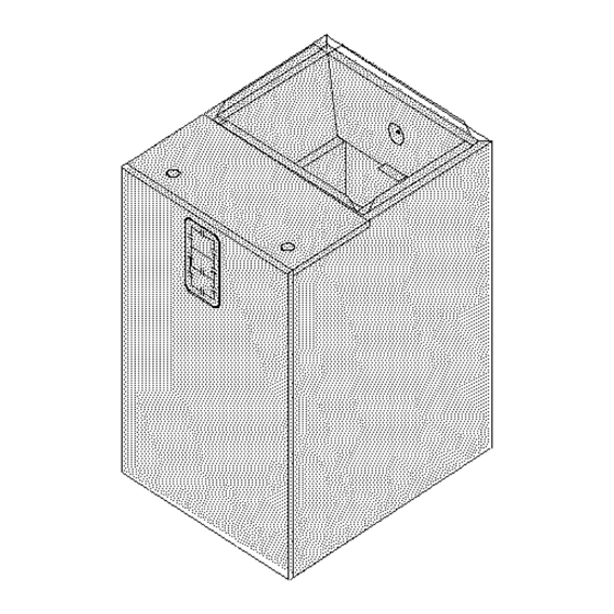
Page 2: General Information
Figure i Nominal Installation Dimensions and Clearances-in(ram) CLEARANCES 12-7/16" (316/- MF08 15-3/4" (400)- MF12 NO HEATERS 19-1/4" (489)- MF16 All Sides...0" 22-3/4" (578)- MF20 From Supply Duct_.0" 314" (19) Recommended Service From Front_.20"(508 (Service blower, filter if installed) Low Voltage Entrance WITH HEATERS All Sides...O"... -
Page 3: Installations
DOWNFLOW INSTALLATIONS For upflow and horizontal applications apply foam seal strip around top of coil cabinet. For downflow application apply foam seal strip Refer to instructions with Subbase Kit. around bottom of coil cabinet. Set blower on top of coil cabinet so they are flush. -
Page 4: Duct Connections
2. Use metal strapping orthreaded rodwith angle iron supports under the auxiliary drain p an tosuspend cabinet. These supports MUST run parallel with the length of the cabinet. Refer to Figure ELECTRICAL SHOCK or UNIT DAMAGE HAZARD Ensure that there is adequate room to remove service Failure to follow this warning could result in personal... -
Page 5: Electrical Shock Hazard
Low Voltage Control Connections Wire low-voltage in accordance with wiring label on the blower (also ELECTRICAL SHOCK or UNIT DAMAGE HAZARD refer to Figures 8 - 12. Use 18 AWG color-coded, insulated (35_C Failure to follow this warning could result in personal injury, minimum) wire to make the low-voltage connections... - Page 6 Table Max. Recommended Supply Circuit Supply H.P. Circuit Motor Branch Over- Volts Phase Hertz Amps Circuit current Supply Wire Ground Wire Protectio 75°C copper n Devise # of Max. Ft.(m) # of (Amps) Wires Size Length Wires Size MF08* Single 105 (32) MF12* Single...
-
Page 7: Air Flow Check
When two-stage electric heat is desired (refer to Table 2 - Heat Strip Staging), separate out the pink W3 wire from W2 & E Wiring Layout Heat Pump Unit (Cooling connections. Refer to Table 2-2 and wiring diagram Figure 11. W3 Two-Stage Heat with One Outdoor can be separated... - Page 8 TEMPERATURE RISE CHECK Refer to the Air Flow Data, Table 4, to find the speed setting Temperature rise is the difference between the supply and return air that will most closely provide the required air flow for the temperatures. system. Refer to Motor Speeds and Airflow in these instructions if the NOTE:...
- Page 9 I Table 5 - ELECTRIC HEATHER STATIC PRESSURE DROP Three-Phase Single-Phase EHIA EHIA EHIA EHIA EHIA EHIA EHIA EHIA EHIA EHIA C FM In wc In wc 0.01 0.01 0.01 0.01 0.01 0.01 0.01 0.01 8oo __ OOl OOl 0.01 0.01 0.01 0.01...
- Page 10 blower motor. Y energizes the outdoor 24V low-voltage circuit in Figure 16 Wiring Layout of Humidifier to Heat heat pump to energize compressor. O energizes reversing valve in Pump cooling mode and typically remains energized until the mode is changed to heating.
- Page 11 WIRING DIAGRAM X40159 Rev.C Specifications subject to change without notice.
- Page 12 REPLACEMENT PARTS 55'55 ITEM CURRENT Z_'_ PART# DESCRIPTION PART# DESCRPTION _; _; _; _; B60077-13BLOWERDOORASS'Y ETo0106..01 5R/_CEBO'R'CMFRONT B60077-14 ETo0106..0"2 B60077-15 ETo0106..0_ B60077-16 B60029 PLATEHEATERADAPTER B601C8 =JOA4BRRAILRG-fTtLB='I" B60048 PLATEHEATER FILLER t301888-01VOTCRM3._NTASSY_A',DLEG8) B60106 WIRECHANNEL 1111 1301888-02 B60107 DECKBLOWER RAIL RIGHT/LEFT 2222 E018£0..0_VDTCRASSY(WTHMOTCRM3LNTS) 1/3-P-3_od B60093 FRONTBLOWER DECK 13018£0-05...
Need help?
Do you have a question about the MF080014C and is the answer not in the manual?
Questions and answers