
Related Manuals for Palomar Digicom 100


Summary of Contents for Palomar Digicom 100
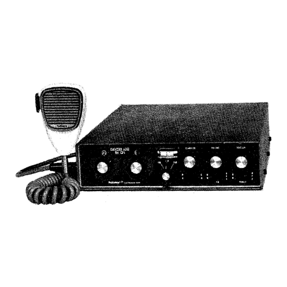
- Page 1 885 A M TRANSCEIVER Owners Manual ELECiRQn iC1, cOR?ORATiQn Escondido, Calif. 92025 Telephone: (714) 746-2666...
- Page 2 I. GENERAL 23 chamel M:"~/SSB Class D Citizens Band two-way radio. Featuses include: The DIGICOTd 100 state modular construction for fast, easy servicing. Ail soiid plug-in Digitally synthesized frequency control for excellent stability and tracking. Unequallied receiver spurious, intermodulation, and cross modulation performance. Internal transmitter ALC to automatically adjust varying microphone input leveb for...
-
Page 3: Before Operating This Unit
BEFORE OPERATING THIS UNIT MUST: form Obtain a Class D license and cail sign &om the FCC, applicatban (FCC ~ r . available from any FCC office or directly from the FCC, Washington, D.C.). Read Part 85 of the FCC Rules and Regulations, This is available from the Superin- tendent of Documents, U.S. - Page 4 This rear bracket could attach to either the transmission tunnel or firewall in vehicle mounting. Place the microphone clip provided in a convenient place that does not interfere with vehicle operation when the microphone is in place. 6 . ZLECTRiCAL CONNECTIONS Use x m b e r twelve or larger wire to connect the unit directly the vehicle 12 volt battery.
-
Page 5: Mode Switch
RADIO OPERATION AYE COKTRWA SWITCH -Turns on power to unit. Lights behind the charnel knobs should A. ON/OFF come on. Locaked lower right corner of front pane!. TRA&Sh3IT SWITCH Located on the side o f the The red iight, in the :mdicatir,g the transmitter is operatke. - Page 6 ]q)-,-7;:- .,,n..-r. . ~ ~ r e of recei.iexi sigraa3s the U S 3 and LSB a i d hntellig~biiity E-',l$ ,ilj~,,,l., rrto2e. Peaks ,-~a:c.:~~~? sirength.in the AM mode. The classier should normally ,bfj1!3! he set rotatbm? poirrt (pointer on knob straight u p ) .
- Page 7 L. EXT SPKR JACK Located on bottom on unit, next to speaker grill. May be used for either an external speaker or public address system. Use 4-8 ohm speaker. IM- PORTANT! Be sure center conductor of speaker plug is connected to ungrounded side of the voice coil.
- Page 8 channel channel...
- Page 9 TRANSMITTER TUNING PROCEDURES I. SYNTHESIZER BOARD (7H001) A. Complete Aligment Rocedure PRELIMINARY SET UP EQUIPMENT REQUIRED VOM, high input inlpedance frequency p l a s ~ c hex RF dunmy counter, 13.6 VDC power supply, h i n g tool, 50 ohm load Connect radio to DC supply Remove PL 1 from R / T board...
- Page 10 Connect counter to Key radio (no RF output should be present a s PL1 was removed from R b a r d ) . Adjust 645 with plastic blade tuning tool for 12.8 TP3. Set all frequencies within 1 0 H z . Unkey radio.
- Page 11 OPERATING INJECTION INJECTION CHANNEL FREQ (MHZj MHz) FREQ (MHz) F R E Q Reconnect board.
- Page 12 SET UP PREEI~~~%'%lNARY power supply, o h k F d l m m y load and Equipxent rizcjuised 13.6VDC ~ a t ~ e t e r oscillcs~fipe ~ ~ p e d a n c e Tektronix IOi! ?Y:% wi", high probe or fq5;,lvaleilY;.
- Page 13 rexiova microphone coriL?ec";i3se scope T?4 and set R251 for. .5 v Coxriect P audio rotation R273 T"6 ar,d paref-ilLl3 ~ e a k LIZ, L 1 1 . .zzd ' J opL<e.c",mo& t&.j 27.igfj i~A.;l..r;.m-~,~ MHz voltage at TP6 moife switch and adjust RSO synthesizer board) for...
- Page 14 Making sure mode switck is still in AM position, set RF output to 3,5w by turning slowly R273 GCW. Check R F output on channels for balance. they are mequal, tweak L:l slightly for balance. back on channel raiiio Remove audio generator connection and PTT clip leader. Set mode switch to USB 1 4 .
-
Page 15: Preliminary Setup
DIGICOM 100 RECEIVER ALIGNMENT PROCEDURE PRELIMINARY SETUP Skble signal generator with A % mdulatien capabiaieq-, Equipment Required ascilkoscope, hex tuning tool. rohtion (pointer straight up). 2. Set R150, R160, R E 8 and Rl3O ant.mil,% corn-ectc~a, 3. Cramect the signal generator to rear pane! - Page 16 squelch per.;, set Iv p-p audio by adjusting R160, This sets the IF 4. Witdl the TP-8 AGC. signal Icvel up LT and mekr r e a m g . This caEbaa%es to 10 R278 Farn S-meter. set Ri%O for 1V DC at sets the RF signal level up...
Need help?
Do you have a question about the Digicom 100 and is the answer not in the manual?
Questions and answers