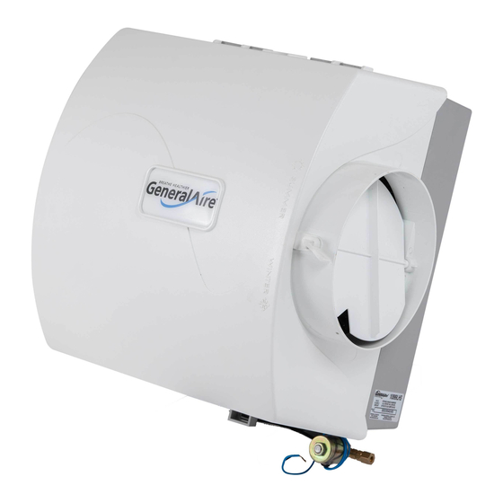
GeneralAire 1099LHS Installation Instructions Manual
Flow-through bypass humidifier
Hide thumbs
Also See for 1099LHS:
- Instruction manual (8 pages) ,
- Installation & owner's manual (12 pages) ,
- Owner's manual (3 pages)
Advertisement
Available languages
Available languages
1099LHS
INSTALLER:
PLEASE
FiLL OUT AND MAiL GUARANTEE
CARD AFTER
INSTALLATION
IS COMPLETE.
LEAVE INSTALLATION
INSTRUCTIONS
WITH HOME OWNER
PRECAUTION:
The instalier should be an experien_d
se_i_
technician,
Dis_nsect
electrical power before
beginning installation Do net instat! where temperatures
fail below 32 d_rees
F or where plenum temperatures
ex_d
200 degrees E When widng into a mu_i-speed
blower circuit see Step 7D
iNSTALLATiON:
The humidifier may be mounted with
the T' outlet to the right or !eft by inverting the cabinet and
reversing the posiSons of the distributor trough and drain
R_J.._
pan, The humidifier may be mounted on the wa_
or
return air p!enum with equal effiei_cy_
See Typi_l
Installations,
ADDITIONAL
MATERIALS THAT MAY BE NECESSARY:
_ 114" diameter plastic supp!y tubing or t/4_' copper
Supp_t _abing _r hot water appii_tions
2_ 7" diameter gaivanized
E_y-pass pipe
3. electd_t
wire and wire nuts
4_ current sensing relay (G.F_ Modes #CA50 suggested)
FLOW,THROUGH
BYPASS HUMIDIFIER
FOR INSTALLATION
ON A VERTICAL
PLENUM SURFACE OF ANY
FORCED AIR FURNACE
LOWBOY
Select
tocation on vertica_ surface of warm or return air pIenum for
mounting humidifier,
Tape mounting temptate in place making sure the
template
is ]eve[
Do not tnstaii humidifier
or 7" bypass pipe where the
blanbed off ends of a cooling coi_ will restri_
air flow to the humidifier.
Extend horisentat _nterline
from template to the sdja_nt
plenum, Scribe
7" circle I0" to _5" from side of humidifier_ on cabinet
cantedine,
using
_nnecting
col_ar as guide.
f/j
=
Connect by-pass Pipe to _i!ar
and humid_er
cabinet.Using holes at
top and bottom of side panei discharge, pierce 2 self tapping screws
through by-pass
pipe.
Cut out center section of template
_nd 7" ho_e. Humidifier
is self
retaining.
S|_de top side in first, then s|ide chassis
down_
Levei
chassis and instaii two canter screws. !f by-pass
pipe instaiis to
opposite side of _assis,
bend dip on side discharge, remove s_de
discharge_
and reinstai/
discharge
to opposite
side of chassis
Instaii remaining six screws.
COPPER
TUBING
PLASTIC
TUBING
Mount the self tapping saddle vatve on either a cotd or a hot water
pipe
A side or top mount is best to avoid dogging
from pipe
sediment
Conne_ 1t4" OD_ tubing to the saddle vatve
Copper
tubing requites a brass compression
nut and brass s!eeve_ P_astic
tubing requires a brass _nse_ inside the tubing, a plastic sleeve On
the outside with a brass compression
nut
NOTE: DO NOT USE PLASTIC TUBING ON HOT WATER OR IN
CONTACT
WITH ANY HOT PLENUM
SURFACE
OR DUCT.
INSTALLATION
OF THIS SADDLE
VALVE MUST
MEET
OR
EY.CEED LOCAL CODES AND ORDINANCES°
Advertisement
Table of Contents

Summary of Contents for GeneralAire 1099LHS
- Page 1 1099LHS INSTALLER: PLEASE FiLL OUT AND MAiL GUARANTEE CARD AFTER INSTALLATION FLOW,THROUGH IS COMPLETE. LEAVE INSTALLATION INSTRUCTIONS WITH HOME OWNER BYPASS HUMIDIFIER PRECAUTION: The instalier should be an experien_d se_i_ technician, Dis_nsect electrical power before beginning installation Do net instat! where temperatures...
- Page 2 SADDLE VALVE iNSTALLATiON INSTRUCTIONS Copper Pipe 1. Retract piercing pin into valve body by turning handle _unterclockwise. 2, Screw valve body into upper bracket and tighten 3, Piece rubber gasket over piercing pin_ 4. Assemble saddle ve!ve over cep_r pipe using enclosed screws, nu_ and lower brackeL 5, Tighten screws evenly end firm!y_ Brackets should be pamiiei,, 6, Compiete _mpression...
- Page 3 900-40 PAD _JL 950-1 C HASSIS 900-9 N OZZLE 900-t 0SPOUT GA23 E VAPORATOR GA4235 DiSTRiBUTiON DISTRIBUTOR TROUGH TUBE DAMPER KNOB )ISC 950-2 SiDE PANEL DISCHARGE 950-13 COVER DRAIN PAN GA4299 ORIFICE P'I02 COMPRESSION SLEEVE k"'_ P10! COMPRESSION 747°38 TUB{NG KIT (A_/AI_BLE) P189 B RASS TUBE i NSERT-- FILL OUT AND MAIL THIS...
- Page 4 This humidifier, if propedy registered by the return of the warranty registration cord to the manufacturer, is warranted to the consumer against defec-ts in matenals and workmanship for a period of five years from the date of installation_ Evaporator pads water strainers or metering oririces are not covered by this !imited warranty or any other warranties Any other defective...
- Page 5 DERIVATION VENTILEE INSTALLATEUR : VEU|LL_ REMPLIR ET POSTER _ CARTE DE GARANT|E UNE FOIS L'|NSTALLAT|ON TERMIN_E_ LAISSER LES DiRECTiVES D'iNSTALLATION AU PROPRI_TAIRE DE LA MA|SON. PReCAUTiON : L!ins_ilateur doit _tre un t_hnicien qual_6 et exp6riment_. Couper I'atimentation 61_dque avsnt de commencer iinstsHstion, Ne pas ins|aider Ysppareii dsns un endro_ o_ Js temp6rsture peut descendre...
- Page 6 INSTRUCTIONS D'INSTALLATION POUR LE ROBINIET-VANNE A I_TRIER Tuyau en coivre R_t_acter _atJge _ performlon dana Io corps de _ayunna en toumant Is po_gnee dana ]e sees horaire. 2. Vissar le corps de la vanne dana le support supeneur et sorter. 3 P_ocer Je joint d'_tanch_ite en caoutchouc parodessua ta tJge de Deffora_en.
- Page 7 900-40 _IL 950-1 CHASS|S 900-9 _ UTAGE 900ot 0 BEC BLOC _VAPORETEUR GA4235 TUYAU TUYAU DU DISTRIBUTEUR D_STRlBUTEUR 900-11 _TOUFFOiR BOUTON 950=5 _TOUFFO;R 950°2 SORTIE -950_13 COUVERCLE BAC DE R_CUP_RATiON Pi01 _CROU A COMPRESSION KiT TUYAUTER_E (DISPON_BLE) P101 CORPS DU TAMIS P189 SOUTiEN DE TUBE---.J 'Toumez ie bouton...
- Page 8 Cot h umidi_cateur, s_iiest enregistr6 correctement en retournant ia carte d'enregistrement de ta garantie au fabriquant, est garanti au _nsommateur centre tout defsut de matenaux et de main d'oeuvre pour une _riode de cinq ans _ par|Jr de la date d'instailation. Garnitures de vape_sateur, ecrans de tamis de i'eau ou orifices regulateu_...


Need help?
Do you have a question about the 1099LHS and is the answer not in the manual?
Questions and answers