Table of Contents
Advertisement
Quick Links
Advertisement
Table of Contents

Related Manuals for Altusen SN0132

Summary of Contents for Altusen SN0132
- Page 1 Serial Console Server SN0132 / SN0148 User Manual www.aten.com...
-
Page 2: Fcc Information
Serial Console Server User Manual FCC Information This is an FCC Class A product. In a domestic environment this product may cause radio interference in which case the user may be required to take adequate measures. This equipment has been tested and found to comply with the limits for a Class A digital device, pursuant to Part 15 of the FCC Rules. -
Page 3: User Information
Serial Console Server User Manual User Information Online Registration Be sure to register your product at our online support center: International http://eservice.aten.com Telephone Support For telephone support, call this number: International 886-2-8692-6959 China 86-10-5255-0110 Japan 81-3-5615-5811 Korea 82-2-467-6789 North America 1-888-999-ATEN ext 4988 United Kingdom 44-8-4481-58923... -
Page 4: Package Contents
Copyright © 2013 ATEN® International Co., Ltd. Manual Date: 2013-04-23 Altusen and the Altusen logo are registered trademarks of ATEN International Co., Ltd. All rights reserved. All other brand names and trademarks are the registered property of their respective owners. -
Page 5: Table Of Contents
Rack Mounting ......... . 15 SN0132 / SN0148 Installation ....... . . 19... - Page 6 Serial Console Server User Manual Chapter 3. Super Administrator Setup Overview..........23 First Time Setup .
- Page 7 Serial Console Server User Manual Telnet/SSH ..........53 Port Attributes .
- Page 8 SN0132 / SN0148 ........
-
Page 9: About This Manual
Serial Console Server User Manual About This Manual This User Manual is provided to help you get the most from your Serial Console Server system. It covers all aspects of installation, configuration and operation. An overview of the information found in the manual is provided below. -
Page 10: Conventions
Serial Console Server User Manual Conventions This manual uses the following conventions: Indicates text that you should key in. Monospaced Indicates keys you should press. For example, [Enter] means to press the Enter key. If keys need to be chorded, they appear together in the same bracket with a plus sign between them: [Ctrl+Alt]. -
Page 11: Terminology
For information about all ALTUSEN products and how they can help you connect without limits, visit ALTUSEN on the Web or contact an ALTUSEN Authorized Reseller. Visit ALTUSEN on the Web for a list of locations and telephone numbers: International http://www.aten.com... - Page 12 Serial Console Server User Manual This Page Intentionally Left Blank...
-
Page 13: Chapter 1 Introduction
(NOC) personnel the ability to perform secure, remote data management and out-of-band management of IT assets from anywhere in the world. Available in 32- and 48-port models, the SN0132 / SN0148 console servers fit in 1U of rack space with dual AC and DC power options. With their comprehensive... - Page 14 The SN0132 / SN0148's firmware is upgradeable, so you can stay current with the latest improvements simply by downloading updates from our website. With its advanced features and ease of operation, the SN0132 / SN0148 is the most convenient, most reliable, and most cost effective way to centrally...
-
Page 15: Features
Chapter 1. Introduction Features System Accessibility and Availability Remote serial access for up to 48 servers or other serial devices Secure in-band and out-of-band network access to serial consoles In-band access of Ethernet Browser access with an intuitive GUI Terminal-based access with a menu-driven UI Out-of-band access of dial-up modem Modem dial-in/dial-back/dial-out Front access USB ports for USB storage or for USB-based PC cards... -
Page 16: Security
Serial Console Server User Manual Security SSH and SSL support Supports CA certificates Configurable user permissions for port access and control Configurable group permission for port access and control Local and remote authentication and logging Third-party authentication supports RADIUS, TACACS+, LDAP/AD, and Kerberos IP filtering and MAC filtering System Management... -
Page 17: Serial Device Management
Chapter 1. Introduction Serial Device Management Versatile serial operation modes – supports Real COM, TCP Server, TCP Client, UDP, Serial Tunnel and Virtual Modem 128-bit/256-bit SSL encryption for Real COM, TCP Server, TCP Client, Serial Tunnel and Virtual Modem Virtual Terminal support (VT52, VT100, VT220, VT320) Real COM driver for Windows 2000/XP/Vista/7 and Windows Server 2003/2008 Built-in 15KV ESD protection for serial ports... -
Page 18: Requirements
Serial Console Server User Manual Requirements The devices that connect to the Serial Console Server must support the following serial protocol: RS-232 (protocol or terminal operations) For Console Management operating mode; Telnet/SSH client, a third party client such as PuTTY, or web browser must be installed For the browser-based WinClient ActiveX, SNViewer for console operating mode, and DirectX 8 must be present, and at least 2MB of memory must be available after installation. -
Page 19: Rj-45 To Serial Adapters
Chapter 1. Introduction RJ-45 to Serial Adapters Cat 5e (or higher) cable is required to connect the SN0132 / SN0148 to the RJ-45 Serial Adapters (see page 19). The various RJ-45 to Serial Adapters offered by ALTUSEN are shown in... -
Page 20: Browsers
Serial Console Server User Manual Browsers Supported browsers for logging into the device include the following: Browser Version 6 and higher Chrome 8.0 and higher Firefox Windows 3.5 and higher Linux 3.0 and higher Safari Windows 4.0 and higher 3.1 and higher Opera 10.0 and higher Mozilla... -
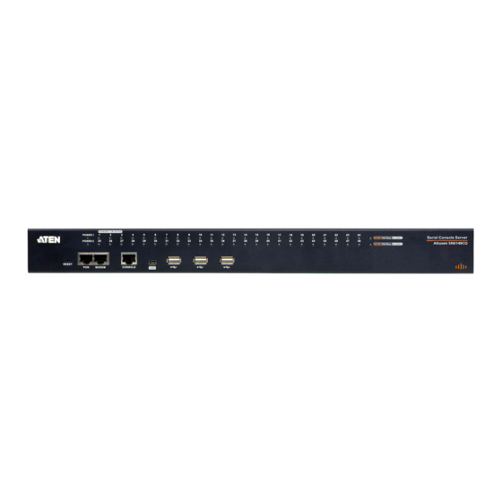
Page 21: Components
Chapter 1. Introduction Components SN0132 Front View SN0148 Front View Component Description Power LEDs Lights when the unit is powered up and ready to operate. Port LEDs The Port LEDs provide status information about their corresponding serial ports. Lights Green: Online – the serial device attached to the port is powered on and ready. - Page 22 Contact your dealer for more information regarding PON units. Modem Port For dial in connection should the unit be unavailable over the network. See SN0132 / SN0148 Installation, page 19, step 6 for installation details. Local Console This RJ45 port allows for local administration and access Port through a serial terminal connection to a computer.
-
Page 23: Sn0132 Rear View (Ac Power)
Chapter 1. Introduction SN0132 Rear View (AC Power) SN0148 Rear View (AC Power) Component Description Grounding The grounding wire that is used to ground the unit attaches Terminal here. Power These standard rocker switches power the unit on and off. -
Page 24: Sn0132 Rear View (Dc Power)
Serial Console Server User Manual SN0132 Rear View (DC Power) SN0148 Rear View (DC Power) Component Description Grounding The grounding wire that is used to ground the unit attaches Terminal here. Power These standard rocker switches power the unit on and off. -
Page 25: Chapter 2. Hardware Setup
You m ust unplug the power cords Stacking and Rack Mounting The SN0132 / SN0148 can be stacked on the desktop or rack mounted in a variety of ways. The following sections take you through the procedures for each method. - Page 26 Serial Console Server User Manual Note: To ensure adequate ventilation, allow at least 5.1 cm on each side, and 12.7 cm behind the unit for power cord and cable clearance.
-
Page 27: Rack Mounting
Chapter 2. Hardware Setup Rack Mounting The SN0132 / SN0148 can be mounted in a 19" (1U) rack. The mounting brackets can screw into either the front or the back of the unit so that it can attach to the front or the back of the rack. - Page 28 Serial Console Server User Manual 3. Position the device in the front of the rack and align the holes in the mounting brackets with the holes in the rack. 4. Screw the mounting brackets to the rack. Note: Cage nuts are provided for racks that are not pre-threaded.
- Page 29 Chapter 2. Hardware Setup Rack Mounting - Rear To mount the unit at the rear of the rack, do the following: 1. Remove the two screws at the rear of the unit. 2. Use the M3 x 8 Phillips head hex screws supplied with the rack mounting kit to screw the rack mounting brackets into the rear of the unit.
- Page 30 Serial Console Server User Manual 4. Screw the mounting brackets to the rear of the rack. Note: Cage nuts are provided for racks that are not prethreaded.
-
Page 31: Sn0132 / Sn0148 Installation
SN0132 / SN0148's rear panel to serial RJ-45 port. 4. Plug the cables that connect the SN0132 / SN0148 to the network into the primary and backup LAN ports, located on the unit’s rear panel. - Page 32 8. (Optional) If you are using a laptop USB console to control the SN0132 / SN0148 locally, use the laptop USB cable included in the package to connect the laptop to the SN0132 / SN0148’s LUC port, located on the unit’s front panel.
-
Page 33: Sn0132 / Sn0148 Installation Diagram
Chapter 2. Hardware Setup SN0132 / SN0148 Installation Diagram SA0141 (DB9-F, DTE-DTE) Modem SA0142 (DB9-M, DTE-DCE) Network Switch SA0142 (DB9-M, DTE-DCE) Network Switch Rollover Cable SA0141 (DB9-F, DTE-DTE) (RJ45-RJ45, DTE-DTE) - Page 34 Serial Console Server User Manual This Page Intentionally Left Blank...
-
Page 35: Super Administrator Setup
Overview This chapter discusses the administrative procedures that the Super Administrator performs to get the SN0132 / SN0148 set up for the first time. First Time Setup Once the SN0132 / SN0148 has been cabled up, the Super Administrator needs to set up the unit for operation. - Page 36 Password: password. Console Login - HyperTerminal Once a physical connection from a computer to the SN0132 / SN0148 has been made you can establish a HyperTerminal session using the instructions below. 1. Open HyperTerminal, and configure the port settings for the COM1 port: Bits per Second: 9600, Data Bits: 8, Parity: None, Stop bits: 1, Flow Control: None.
- Page 37 Chapter 3. Super Administrator Setup 2. When configured correctly the login prompt appears, as shown here: Since this is the first time you are logging in, use the default Username: administrator; and the default Password: password. Local Console Main Menu After you login via HyperTerminal or SNViewerUSB the text based menu appears: The Main Menu is the text based equivalent of the browser based configuration...
-
Page 38: Remote Login
Password: password. PuTTY Login Start PuTTY, enter the SN0132 / SN0148’s default IP address (192.168.0.60), click Open, and a login prompt will appear, as shown here: Since this is the first time you are logging in, use the default Username:... - Page 39 Console Server, do the following: 1. Open the web browser and specify the default IP address (192.168.0.60) of the SN0132 / SN0148 in the browser's location bar, and press Enter. 2. When a Security Alert dialog box appears, accept the certificate, it can be trusted.
-
Page 40: Setup
Serial Console Server User Manual Setup Network Setup To set up the network, do the following: 1. Click the Device Management tab. 2. Select the Network tab. 3. Fill in the fields according to the information provided under Network, page 85. -
Page 41: Changing The Super Administrator Login
Chapter 3. Super Administrator Setup Changing the Super Administrator Login To change the default Super Administrator Username and Password, do the following: 1. At the top of the screen, click the User Management tab. The User Management page has a list of Users and Groups in the Sidebar at the left, and a more detailed list of users –... - Page 42 Serial Console Server User Manual This Page Intentionally Left Blank...
-
Page 43: Chapter 4. The User Interface
Each of the interfaces is described in the sections that follow. Access The SN0132 / SN0148 can be accessed from a local console (locally connected computer or laptop) running terminal application software (such as Microsoft HyperTerminal) or the SNViewerUSB application; or from a remote computer using Telnet (SSH), PuTTY, or web-based browser (see First Time Setup, page 23 for details). -
Page 44: Local Console Operation
Serial Console Server User Manual Local Console Operation When a local console is attached (see SN0132 / SN0148 Installation, page 19), you can use the HyperTerminal or SNViewerUSB application to login (See Local Login, page 23 for details). Simply key in your valid Username and Password, then hit [Enter] to bring up the Local Console Main Page. -
Page 45: Remote Operation
Chapter 4. The User Interface Remote Operation You can access the SN0132 / SN0148 remotely using a web browser, or text based terminal application such as Telnet or PuTTY, as described below. Web Browser Login SN0132 / SN0148 units can be accessed via an Internet browser running on any platform. -
Page 46: The Web Browser Main Page
Serial Console Server User Manual The Web Browser Main Page To ensure multi-platform operability, access to the SN0132 / SN0148 can be accomplished with most standard web browsers. The chapters following this one give detailed information about each section of the web browser. Once... - Page 47 About About provides information regarding the Serial Console Server’s current firmware version. Logout Click this button to log out of your SN0132 / SN0148 session. Welcome Message If this function is enabled (see Welcome Message, page 57), a welcome message displays here.
-
Page 48: The Tab Bar
There are two small icons at the extreme right of the page. Their functions are described in the table, below: Icon Function Click this icon to bring up a panel with information about the Serial ’s Console Server firmware version. Click this icon to log out and end your SN0132 / SN0148 session. -
Page 49: Snviewer
Chapter 4. The User Interface SNViewer The SNViewer is the main application used to access serial devices via web browser. The SNViewer opens from the Port Access - Connections page, when you click the Telnet or SSH button for a serial device (see Telnet/SSH, page 53 for details). -
Page 50: Control Panel Functions
Serial Console Server User Manual Right clicking in the text row area brings up a menu-style version of the toolbar. These functions are discussed in the sections that follow. To move the Control Panel to a different location on the screen, place the mouse pointer over the text row area, then click and drag. - Page 51 Use this to change the page encoding (see Encode, page 40). Use this to enable the broadcast function. Broadcasting allows you use one session to send the same commands to multiple serial devices connected to the SN0132 / SN0148 (see Preferences, page 56 for details). Send Break command Use this to reset the terminal to its default settings.
-
Page 52: Data Import
Serial Console Server User Manual Data Import The Data Import page opens a standard browse menu to import data files, as shown below: Encode Encoding allows you select which type of encoding you want to use. Make your selection from the drop down menu and click OK, as shown below: Terminal Settings The Terminal Settings page allows you make changes to the appearance of the terminal window, as described below:... - Page 53 Chapter 4. The User Interface Category Description Font Click Change to configure the SNViewer’s Font settings. You can change the Font type, Size, and Style. On the right side of the window you can view an example of the font you have set. Color Select an Option: Foreground color, Background Color, Cursor Text color, or Cursor Color, and Click Change to adjust the color settings.
-
Page 54: Macros
Serial Console Server User Manual Macros Macros allow you to create custom text macros to use within the SNViewer application. When you click the Macros icon the following screen appears: Simply check a box, type in the text macro and click Save. Use the associated function key (F1-F12) to run the custom text macro(s) you created. - Page 55 Chapter 4. The User Interface Compose Panel Key in the messages that you want to post to the board in this panel. Click Send to post the message to the board. User List Panel The username and IP address of all the logged in users are listed in this panel. If you check All Users, messages are posted to all users.
-
Page 56: Terminal Application
Serial Console Server User Manual Terminal Application You can login remotely using a text based terminal application such as Telnet, or PuTTY. For information on how to connect and login, see Remote Login, page 26 for details. The Telnet and PuTTY Main Menus are the text based equivalent of the browser based configuration and control functions described throughout this manual. -
Page 57: Chapter 5. Port Operating Modes
Chapter 5 Port Operating Modes Overview To cover a broad range of serial applications, the SN0132 / SN0148’s COM ports support several port operating modes. These include Virtual Modem, Serial Tunnel, Console Management, and Real COM Port modes, for device control sessions, plus TCP Server/Client and UDP modes for socket application purposes. -
Page 58: Work Mode
Console Management Console Management mode is the most common Work Mode used, allowing users to establish Telnet or SSH sessions to the SN0132 / SN0148 to manage the serial devices. In this mode users can login using the web browser’s built in SNViewer application via Telnet or SSH;... -
Page 59: Tcp Server / Tcp Client
TCP Server (RAW TCP) In TCP Server (RAW TCP) mode, data transmission is bidirectional. In this mode, the host computer initiates contact with the SN0132 / SN0148 and requests a connection to its serial port. Once the connection is established, the host receives data from the serial device. -
Page 60: Udp Mode
TCP which is optimized for data accuracy. Serial Tunnel Serial Tunnel involves establishing a direct connection between two SN0132 / SN0148’s over ethernet. Serial Tunnel works in a master/slave relationship. One unit is designated master, the other designated slave. -
Page 61: Chapter 6 Port Access
Sidebar at the left of the page. In addition to Serial Console Server device listings, if any PDU / PON (Power Over the Net™) devices are connected to the SN0132 / SN0148 they are listed separately below the port listings. -
Page 62: The Sidebar
Serial Console Server User Manual The Sidebar All connected Serial Console Servers, port devices and PDU devices – including their ports and outlets – are listed in a tree structure in the Sidebar at the left of the screen: The Sidebar Tree Structure The characteristics of the Sidebar tree structure are: Users are only allowed to see the devices and ports that they have access permission for. -
Page 63: Filter
Chapter 6. Port Access Filter The Filter allows you to control the number and type of ports that display in the Sidebar. When you click Filter, the bottom of the panel changes to look similar to the image, below: The meanings of the choices are explained in the following table: Choices Explanation Search... -
Page 64: Connections
Serial Console Server User Manual Connections The main panel on the Connections page displays the Port List. From here you can select and connect to the serial devices via the port they are connected to. Heading Description Port Number This column represents the physical port that the device is connected to on the rear of the Serial Console Server. -
Page 65: Telnet/Ssh
Telnet/SSH To access a serial device connected to the SN0132 / SN0148, click the port’s Telnet or SSH button from the Port Access - Connections page: The Serial Console Server opens SNViewer to start your session with the serial... -
Page 66: Port Attributes
Serial Console Server User Manual Port Attributes Clicking a device on the sidebar from the Port Access - Connections page brings up the Port Attributes page with detailed information about the device and Power Over the Net™ reboot options, as shown here: From here you can use the Telnet, SSH, and Dump Buffer buttons at the bottom of the page, or reboot a device connected to an associated Power Over the Net™... -
Page 67: Favorites
Chapter 6. Port Access Favorites The Favorites tab allows you to keep all the connections that you access most frequently in one convenient place. To add a port to Favorites, right-click on it from the sidebar and select Add to Favorites, or select a port and click Add. The layout and functions available on the Favorites tab are exactly the same as those found on the Port List tab (See Connections, page 52 for details). -
Page 68: Preferences
Logout Timeout If there is no user input for the amount of time set with this function, the user is automatically logged out. Once logged out, a login is necessary before the SN0132 / SN0148 can be accessed again. Broadcast Timeout If there is no user input for the amount of time set here, the Broadcast function is automatically ended. - Page 69 Chapter 6. Port Access Setting Function Viewer You can choose which viewer is used when accessing a serial device: Auto Detect will select the appropriate viewer based on the web browser used; WinClient for Windows Internet Explorer, Java Client for other web browsers (ex. Firefox). Java Client will open the Java based viewer regardless of the web browser being used.
-
Page 70: Sessions
Serial Console Server User Manual Sessions The Session page lets the administrator and users with User Management permissions see at a glance which users are currently logged into the Serial Console Server, and provides information about each of their sessions. Note: 1. -
Page 71: Access
Chapter 6. Port Access Access Administrators use the Access page to set user and group access and configuration rights for Serial Console Server ports and PDU devices. The Access page only appears for those users with User Management permissions and isn't available for other users. Access rights can be set on a user-by-user or a group-by-group basis. - Page 72 Serial Console Server User Manual Access Rights The Access columns are where access rights are set. The meaning of each is explained below. Full Access The user can view the device and can perform operations on the device. View Only The user can only view the device;...
-
Page 73: Properties
Chapter 6. Port Access Properties When you click the Properties tab, the Port Settings List page appears: When a port is double clicked from the Port Settings List or from the Sidebar, the Properties page appears and looks similar to the one below: This panel allows you to make configuration settings for the selected port, as explained in the table below: Setting... - Page 74 Serial Console Server User Manual Setting Meaning Port Name You can give a port an appropriate name by editing the Port Name field. Baud Rate – This sets the port’s data transfer speed. Choices are from 300 115200 (drop down the list to see all options). Set this to match the baud rate setting of the connected device.
-
Page 75: Port Buffering
Chapter 6. Port Access Port Buffering Port Buffering creates a log of activity conducted when a port is accessed. You can save the log to memory on the Serial Console Server, or to a USB device. A USB device provides more storage space, while the Serial Console Server is limited to it’s internal memory. -
Page 76: Operation Mode
Serial Console Server User Manual Operation Mode The Operation Mode page allows you to configure settings for access and management of each port. This determines how each serial device is accessed via operating modes. Work Mode – This sets the mode you use to access the port device for management. - Page 77 SNMP Trap event has been triggered – debug messages can be sent through its serial port to the SN0132 / SN0148’s COM port. When the SN0132 / SN0148 receives such a message, it can send an SNMP Trap alert and/or an email to inform the user specified here of the problem. You...
- Page 78 Serial Console Server User Manual After setting up this page, whenever one of the specified alerts is generated, you will be informed of its occurrence. Command Filters On this page you can specify up to 16 command filters.
-
Page 79: Chapter 7. User Management
Chapter 7 User Management Overview When you select the User Management tab the screen comes up with the Accounts page displayed: The page is organized into two main areas: the Sidebar at the left, and the large main panel at the right. Users and groups appear in the panel at the left of the page. -
Page 80: Users
Serial Console Server User Manual Users The Serial Console Server supports three user types, as shown in the table bellow: User Type Role Super Administrator Access and manage ports and devices. Manage Users, and Groups. Configure the overall installation. Configure personal working environment. - Page 81 Permissions Enabling Device Admin allows a user to configure and control the settings for overall SN0132 / SN0148 operations (see Device Management, page 83). Enabling User Admin allows a user to create, modify, and delete user and group accounts.
- Page 82 Serial Console Server User Manual Field Description Status Status allows you to control the user’s account and access to the installation, as follows: Disable Account lets you suspend a user’s account without actually deleting it, so that it can be easily reinstated in the future.
-
Page 83: Modifying User Accounts
Chapter 7. User Management 7. Click Users in the Sidebar to return to the main screen. The new user appears in the Sidebar list and in the main panel, as well. The Sidebar Users list can expand and collapse. If the list is expanded, click the minus symbol ( –... -
Page 84: Groups
Serial Console Server User Manual Groups Groups allow administrators to easily and efficiently manage users and devices. Since device access rights apply to anyone who is a member of the group, administrators need only set them once for the group, instead of having to set them for each user individually. - Page 85 Chapter 7. User Management 3. Enter the required information in the appropriate fields. A description of each of the fields is given in the table below: Field Description Group Name A maximum of 16 characters is allowed. Description Additional information about the user that you may wish to include.
-
Page 86: Modifying Groups
Serial Console Server User Manual Modifying Groups To modify a group, do the following: 1. In the Sidebar Group list, click the group’s name – or – In the main panel, select the group’s name. 2. Click Modify. 3. In the Group notebook that comes up, make your changes, then click Save. Note: The Group page is discussed on page 72;... -
Page 87: Users And Groups
Chapter 7. User Management Users and Groups There are two ways to manage users and groups: from the Users notebook; and from the Group notebook. Note: Before you can assign users to groups, you must first create them. See Adding Users, page 68 for details. Assigning Users to a Group From the User’s Notebook To assign a user to a group from the User’s notebook, do the following: 1. -
Page 88: Removing Users From A Group From The User's Notebook
Serial Console Server User Manual Removing Users From a Group From the User’s Notebook To remove a user from a group from the User’s notebook, do the following: 1. In the Sidebar User list, click the user’s name – or – In the main panel, select the user’s name. -
Page 89: Assigning Users To A Group From The Group's Notebook
Chapter 7. User Management Assigning Users to a Group From the Group’s Notebook To assign a user to a group from the Group notebook, do the following: 1. In the Sidebar Group list, click the group’s name – or – In the main panel, select the group’s name. -
Page 90: Removing Users From A Group From The Group's Notebook
Serial Console Server User Manual Removing Users From a Group From the Group’s Notebook To remove a user from a group from the Group’s notebook, do the following: 1. In the Sidebar Group list, click the group’s name – or – In the main panel, select the group’s name. -
Page 91: Device Assignment
Chapter 7. User Management Device Assignment When a user logs in to the Serial Console Server, the interface comes up with the Port Access page displayed. All the ports that the user is permitted to access are listed in the Sidebar at the left of the page. Access permissions for those ports and the devices connected to them are assigned on a port-by-port basis from the User or Group list on the Sidebar of the User Management page. - Page 92 Serial Console Server User Manual 4. Make your permission settings for each port according to the information provided below: Name: Each port accessible to the user is listed under the Names column. Access: The Access column is where device access rights are set. Click the radio buttons in the rows that corresponds your choices.
-
Page 93: Assigning Device Permissions From The Groups' Notebook
Chapter 7. User Management Assigning Device Permissions From the Groups’ Notebook To assign a device permissions to a Group of users, do the following: 1. In the Sidebar Groups list, click the group’s name – or – In the main panel, select the group’s name. 2. - Page 94 Serial Console Server User Manual This Page Intentionally Left Blank...
-
Page 95: Chapter 8. Device Management
Chapter 8 Device Management Devices The Device Management page opens with the top level SN0132 / SN0148 selected in the Sidebar, with all its ports nested below, and the Device Information page displaying in the main panel: General The General section of the Device Information page displays and allows you to set the Name and Description of the Serial Console Server. - Page 96 Serial Console Server User Manual When the Power Supply Detection function is enabled (there is a check in the checkbox), when there is only one source of power, the Serial Console Server will beep to warn you of the problem. The default for this function is enabled.
-
Page 97: Network
Chapter 8. Device Management Network The Network page is used to specify the network environment. Each of the elements on this page is described in the sections that follow. - Page 98 IP Installer utility. See IP Installer, page 129, for IP Installer details. Note: 1. If you select View Only, you will be able to see the SN0132 / SN0148 in the IP Installer’s Device List, but you will not be able to change the IP address.
- Page 99 If you choose not to enable the Redundant NIC function, the two NICs can be configured with separate interfaces. Users can log into the SN0132 / SN0148 with either IP address. To set up the Serial Console Server with this configuration, do the following: 1.
- Page 100 Serial Console Server User Manual IPv4 Settings IP Address: IPv4 is the traditional method of specifying IP addresses. The SN0132 / SN0148 can either have its IP address assigned dynamically (DHCP), or it can be given a fixed IP address.
- Page 101 IP Address: IPv6 is the new (128-bit) format for specifying IP addresses. (See IPv6, page 131 for further information.) The SN0132 / SN0148 can either have its IPv6 address assigned dynamically (DHCP), or it can be given a fixed IP address.
-
Page 102: Anms
Event Destination SMTP Settings To have the SN0132 / SN0148 email reports from the SMTP server to you, do the following: 1. Enable the Enable report from the following SMTP server, and key in either the IPv4 address, IPv6 address, or domain name of the SMTP server. - Page 103 The total cannot exceed 256 Bytes. Log Server Important transactions that occur on the SN0132 / SN0148, such as logins and internal status messages, are kept in an automatically generated log file. To enable this, put a check in the Enable report from the following Log Server checkbox.
- Page 104 Serial Console Server User Manual SNMP Server Up to four SNMP management stations can be specified. If you want to use SNMP trap notifications, do the following: 1. Check Enable SNMP Trap and key in the Community. 2. Key in the IP address(es) and the service port number(s) of the computer(s) to be notified of SNMP trap events.
- Page 105 Chapter 8. Device Management Syslog Server To record all the events that take place on SN0132 / SN0148 and write them to a Syslog server, do the following: 1. Check Enable. 2. Key in either the IPv4 address, IPv6 address, or domain name of the Syslog server.
- Page 106 Alternate RADIUS servers. You can use the IPv4 address, the IPv6 address or the domain name in the IP fields. 3. In the Timeout field, set the time in seconds that the SN0132 / SN0148 waits for a RADIUS server reply before it times out.
- Page 107 SN0132 / SN0148. In each case, the user’s access rights are the ones assigned that were assigned when the User of Group was created on the SN0132 / SN0148. (See Adding Users, page 68.) LDAP / LDAPS Authentication and Authorization Settings...
- Page 108 Serial Console Server User Manual On the LDAP / LDAPS server, Users can be authenticated with any of the following methods: With MS Active Directory schema. Note: If this method is used, the LDAP schema for MS Active Directory must be extended. Without schema – Only the Usernames used on the Serial Console Server are matched to the names on the LDAP / LDAPS server.
- Page 109 Chapter 8. Device Management CC Management Settings To allow authorization for the SN0132 / SN0148 through a CC (Control Center) server, check Enable and fill in the CC Server’s IP address and Service port in the appropriate fields. You can use the IPv4 address, the IPv6 address or the domain name in the CC Server IP field.
-
Page 110: Oobc
Serial Console Server User Manual OOBC In case the Serial Console Server cannot be accessed with the usual LAN-based methods, it can be accessed via the Serial Console Server’s modem port. To enable support for PPP (modem) operation, click to put a checkmark in the Enable Out of Band Access checkbox. - Page 111 Chapter 8. Device Management Enable Dial Back As an added security feature, if this function is enabled, the Serial Console Server disconnects the calls that dial in to it, and dials back to one of the entries specified in the table below: Item Action Enable Fixed...
- Page 112 Serial Console Server User Manual Item Action Emergency Dial If the Serial Console Server gets disconnected from the network, or the network goes down, this function puts the Serial Console Server on line via the ISP dial up connection. If you choose PPP stays online until network recovery, the PPP connection to the ISP will last until the network comes back up or the Serial Console Server reconnects to it.
-
Page 113: Security
Chapter 8. Device Management Security The Security page is divided into 4 main panels, as described in the sections that follow. Login Failures For increased security, the Login Failures section allows administrators to set policies governing what happens when a user fails to log in successfully. To set Login Failures, check one of the Login Fail Policy checkboxes. - Page 114 Serial Console Server User Manual IP/MAC Filter IP and MAC Filtering IP and MAC Filters control access to the Serial Console Server based on the IP and/or MAC addresses of the client computers attempting to connect. A maximum of 100 IP filters and 100 MAC filters are allowed. If any filters have been configured, they appear in the IP Filter and/or MAC Filter list boxes.
- Page 115 Chapter 8. Device Management 5. Repeat these steps for any additional IP addresses you want to filter. To add a MAC filter, do the following: 1. Click Add. A dialog box appears 2. Specify the MAC address in the dialog box, then click OK. 3.
- Page 116 Serial Console Server User Manual Account Policy In the Account Policy section, system administrators can set policies governing usernames and passwords. The meanings of the Account Policy entries are explained in the table below: Entry Explanation Minimum Username Length Sets the minimum number of characters required for a username.
-
Page 117: Association
Chapter 8. Device Management Association The Association tab lets you make your power management settings, such as synchronizing on/off/reboot, with associated PON (Power Over the Net™) devices. Power Management The Power Management page is used to associate a PON outlet with a serial device’s port on the Serial Console Server. - Page 118 Serial Console Server User Manual To associate a PON outlet with a serial port, from the Power Management page, do the following: 1. In the Sidebar tree, select the serial port you want to associate with the PON outlet. 2. From the PON Associate Settings, click Add. 3.
- Page 119 Chapter 8. Device Management 4. (Optional) If the device connected to the Serial Console Server's port has a dual power supply and you wish to associate additional outlets, simply click Add to select another outlet to associate with the port. You can associate up to four outlet ports to a connected device.
-
Page 120: Date/Time
Serial Console Server User Manual Date/Time The Date/Time dialog page sets the SN0132 / SN0148 time parameters: Set the parameters according to the information below. Time Zone To establish the time zone that the Serial Console Server is located in, drop down the Time Zone list and choose the city that most closely corresponds to where it is at. - Page 121 Chapter 8. Device Management Date Select the month from the dropdown listbox. Click < or > to move backward or forward by one year increments. In the calendar, click on the day. To set the time, use the 24 hour HH:MM:SS format. Click Set to save your settings.
- Page 122 Serial Console Server User Manual This Page Intentionally Left Blank...
-
Page 123: Chapter 9 Log
Chapter 9 Overview The SN0132 / SN0148 logs all the events that take place on it. To view the contents of the log, click the Log tab. The device’s System Log page appears: System Log The System Log page displays events that take place on the SN0132 / SN0148, and provides a breakdown of the time, the severity, the user, and a description of each one. -
Page 124: Filter
Serial Console Server User Manual Filter Filter lets you narrow the log event display to ones that occurred at specific times; ones containing specific words or strings; or ones involving specific users. When you access this function, the log filter dialog box appears at the bottom of the page: A description of the filter items is given in the table, below: Item... - Page 125 Chapter 9. Log Item Description Pattern Filters for a particular word or string. Key the word or string into the Information text box. Only events containing that word or string are displayed. Wildcards (? for single characters; * for multiple characters) and the keyword or are supported. E.g., h*ds would return hands and hoods;...
-
Page 126: Log Notification Settings
Serial Console Server User Manual Log Notification Settings The Notification Settings page lets you decide which events trigger a notification: The notifications are grouped into five groups: You can choose to enable the following: All system events All authentication events All user management events All device management events All system task events... -
Page 127: Chapter 10 Maintenance
Chapter 10 Maintenance Overview The Maintenance function is used to upgrade firmware; backup and restore configuration and account information; and restore default values. Backup / Restore When you click on the Maintenance tab, it opens with the Backup/Restore page. This page gives you the ability to back up the Serial Console Server’s configuration and user profile information:... -
Page 128: Backup
Serial Console Server User Manual Backup To backup the device’s settings do the following: 1. In the Password field, key in a password for the file. Note: 1. Setting a password is optional. If you do not set one, the file can be restored without specifying a password. -
Page 129: Firmware Upgrade
Chapter 10. Maintenance Firmware Upgrade This page can be used to upgrade the SN0132 / SN0148’s firmware. As new versions of the firmware become available, they can be downloaded from our website. Check the website regularly to find the latest information and packages. -
Page 130: Certificates
Serial Console Server User Manual Certificates This page provides information on the Private Certificates: Private Certificate When logging in over a secure (SSL) connection, a signed certificate is used to verify that the user is logging in to the intended site. For enhanced security, the Private Certificate section allows you to use your own private encryption key and signed certificate, rather than the default ATEN certificate. - Page 131 Chapter 10. Maintenance After the CA sends you the certificate and private encryption key, save them to a convenient location on your computer. Importing the Private Certificate To import the private certificate, do the following: 1. Click Import from the bottom of the Private Certificate page, shown here: 2.
- Page 132 Serial Console Server User Manual Certificate Signing Request The Certificate Signing Request (CSR) section provides an automated way of obtaining and installing a CA signed SSL server certificate. To perform this operation do the following: 1. Click New. The following dialog box appears: 2.
- Page 133 Chapter 10. Maintenance 4. Click Get CSR, and save the certificate file (csr.cer) to a convenient location on your computer. This is the file that you give to the third party CA to apply for their signed SSL certificate. 5. After the CA sends you the certificate, save it to a convenient location on your computer.
- Page 134 Serial Console Server User Manual This Page Intentionally Left Blank...
-
Page 135: Appendix
Appendix Safety Instructions General This product is for indoor use only. Read all of these instructions. Save them for future reference. Follow all warnings and instructions marked on the device. Do not place the device on any unstable surface (cart, stand, table, etc.). If the device falls, serious damage will result. - Page 136 Serial Console Server User Manual If an extension cord is used with this device make sure that the total of the ampere ratings of all products used on this cord does not exceed the extension cord ampere rating. Make sure that the total of all products plugged into the wall outlet does not exceed 15 amperes.
-
Page 137: Rack Mounting
Appendix Rack Mounting Before working on the rack, make sure that the stabilizers are secured to the rack, extended to the floor, and that the full weight of the rack rests on the floor. Install front and side stabilizers on a single rack or front stabilizers for joined multiple racks before working on the rack. -
Page 138: Technical Support
Serial Console Server User Manual Technical Support International For online technical support – including troubleshooting, documentation, and software updates: http://support.aten.com For telephone support, see Telephone Support, page iii North America Email Support support@aten-usa.com Online Troubleshooting http://www.aten-usa.com/support Technical Documentation Support Software Updates Telephone Support 1-888-999-ATEN ext 4988 When you contact us, please have the following information ready beforehand:... -
Page 139: Specifications
Appendix Specifications SN0132 / SN0148 Function SN0132 SN0148 Serial Connections Connectors RS-232 Serial Ports 32 x RJ45 Female 48 x RJ45 Female (Black) (Black) 2 x RJ-45 Power 2 x 3-prong AC socket 1 x RJ45 Female (Black) Modem 1 x RJ45 Female (Black) -
Page 140: Sn0132D / Sn0148D
Serial Console Server User Manual SN0132D / SN0148D Function SN0132D SN0148D Serial Connections Connectors RS-232 Serial Ports 32 x RJ45 Female 48 x RJ45 Female (Black) (Black) 2 x RJ-45 Power DC Terminal 1 x RJ45 Female (Black) Modem 1 x RJ45 Female (Black) 3 x USB Type A Female (White) USB Console 1 x Mini USB... -
Page 141: Ip Address Determination
Appendix IP Address Determination If you are an administrator logging in for the first time, you need to access the Serial Console Server in order to give it an IP address that users can connect to. There are three methods to choose from. In each case, your client computer must be on the same network segment as the Serial Console Server. -
Page 142: Browser
Serial Console Server User Manual 3. Select the Serial Console Server in the Device List. Note: 1. If the list is empty, or your device doesn't appear, click Enumerate to refresh the Device List. 2. If there is more than one device in the list, use the MAC address to pick the one you want. -
Page 143: Ipv6
Appendix IPv6 At present, the Serial Console Server supports three IPv6 address protocols: Link Local IPv6 Address, IPv6 Stateless Autoconfiguration, and Stateful Autoconfiguration (DHCPv6). Link Local IPv6 Address At power on, the Serial Console Server is automatically configured with a Link Local IPv6 Address (for example, fe80::210:74ff:fe61:1ef). -
Page 144: Ipv6 Stateless Autoconfiguration
Serial Console Server User Manual IPv6 Stateless Autoconfiguration If the Serial Console Server network environment contains a device (such as a router) that supports the IPv6 Stateless Autoconfiguration function, the Serial Console Server can obtain its prefix information from that device in order to generate its IPv6 address. -
Page 145: Virtual Modem Details
WAN using TCP/IP rather than over slower, less-reliable, telephone lines. AT Command Set Support The SN0132 / SN0148 supports a subset of the standard Hayes command set, as well as some extended commands, as shown in the following table: Command... - Page 146 Serial Console Server User Manual (Continued from previous page.) Command Operation Response ATZ[CR] Reset modem command. If successful: OK[CR][LF] If failure: ERROR[CR][LF] Close active connections and reset the S registers and general option status to their saved values. AT&Cn[CR] DCD option. (Where n represents a numeric If successful: OK[CR][LF] character;...
-
Page 147: Port Forwarding
Appendix Port Forwarding For devices located behind a router, port forwarding allows the router to pass data coming in over a specific port to a specific device. By setting the port forwarding parameters, you tell the router which device to send the data that comes in over a particular port to. -
Page 148: Internal Serial Interface Configuration
Serial Console Server User Manual Internal Serial Interface Configuration The Serial Console Server provides a function that lets you configure an attached device’s serial interface parameters from within any accessed server. To do so: 1. From the accessed server, open a command line (terminal) session or third party serial application such as HypterTerminal or PuTTY. -
Page 149: Operation
Appendix Operation ↑ ↓ Use the Up and Down Arrow Keys ( ) to highlight a device in the left panel, then press [Enter] to open a command line (terminal) session on the accessed device. When you have finished with your session, press the hotkey (see page 137 and 138) that brings you back to the access page. -
Page 150: Port Level Configuration
Serial Console Server User Manual Port Level Configuration When a serial interface device is selected in the left panel, The screen looks similar to the one below: The configuration settings that can be made when a serial interface device is selected are described in the table, below: Setting Description... -
Page 151: Trusted Certificates
Appendix Trusted Certificates Overview When you try to log in to the device from your browser, a Security Alert message appears to inform you that the device’s certificate is not trusted, and asks if you want to proceed. The certificate can be trusted, but the alert is triggered because the certificate’s name is not found on Microsoft list of Trusted Authorities. -
Page 152: Installing The Certificate
Serial Console Server User Manual Installing the Certificate To install the certificate, do the following: 1. In the Security Alert dialog box, click View Certificate. The Certificate Information dialog box appears: Note: There is a red and white X logo over the certificate to indicate that it is not trusted. -
Page 153: Certificate Trusted
Appendix Certificate Trusted The certificate is now trusted: When you click View Certificate, you can see that the red and white X logo is no longer present – further indication that the certificate is trusted:... - Page 154 Serial Console Server User Manual Mismatch Considerations If the site name or IP address used for generating the certificate no longer matches the current address of the Serial Console Server a mismatch warning occurs. You can click Yes to go on, or you can disable mismatch checking. To disable mismatch checking, do the following: 1.
-
Page 155: Self-Signed Private Certificates
Appendix Self-Signed Private Certificates If you wish to create your own self-signed encryption key and certificate, a free utility – openssl.exe – is available for download over the web at www.openssl.org. To create your private key and certificate do the following: 1. -
Page 156: Clear Login Information
Serial Console Server User Manual Clear Login Information If you are unable to perform an Administrator login (because the Username and Password information has become corrupted or you have forgotten it, for example) you can clear the login information with the following procedure. Note: Performing this procedure also returns all settings to their defaults. -
Page 157: Limited Warranty
ALTUSEN warrants this product against defects in material or workmanship for a period of one (1) year from the date of purchase. If this product proves to be defective, contact ALTUSEN's support department for repair or replacement of your unit. ALTUSEN will not issue a refund. - Page 158 Serial Console Server User Manual This Page Intentionally Left Blank...
Need help?
Do you have a question about the SN0132 and is the answer not in the manual?
Questions and answers