
Related Manuals for LDG SLS-2


Summary of Contents for LDG SLS-2
- Page 1 SLS-2 OPERATIONS MANUAL MANUAL REV. A LDG SLS-2 Two-Port RJ45 Switch LDG Electronics 1445 Parran Road St. Leonard MD 20685-2903 USA Phone: 410-586-2177 Fax: 410-586-8475 ldg@ldgelectronics.com www.ldgelectronics.com PAGE 1...
-
Page 2: Table Of Contents
SLS-2 OPERATIONS MANUAL MANUAL REV. A Table Of Contents Introduction Jumpstart, or “Real hams donʼt read manuals!” Specifications Important Safety Warning Getting to know your SLS-2 Front Panel Rear Panel Inside Installation Operation Desktop / Local Operation Remote Operation Application Information... -
Page 3: Introduction
Ok, but at least read this one section before operating the SLS-2: 1. The SLS-2 allows you to switch 8 circuits of an RJ45 common jack to one of the two switched jacks. The default SLS-2 wiring is such that the port pinouts are 1-to-1, i.e. straight-through wiring. -
Page 4: Getting To Know Your Sls-2
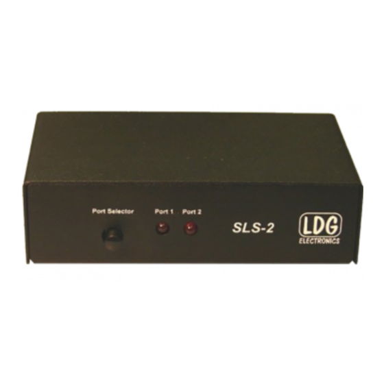
SLS-2 OPERATIONS MANUAL MANUAL REV. A GETTING TO KNOW YOUR SLS-2 Your SLS-2 is a quality, precision instrument that will give you many years of outstanding service; take a few minutes to get to know it. Front Panel On the front panel there is one pushbutton and two LED indicator lights. The button is a pushbutton toggle switch which selects between the two cables connected to the rear ports. -
Page 5: Rear Panel
MANUAL REV. A Rear Panel The rear panel of the SLS-2 features three RJ45 jacks. One is a common jack, and the other two are the switched jacks. The front panel pushbutton alternately connects either Port 1 or Port 2 to the Common Port. -
Page 6: Inside
SLS-2. If you open the case of the SLS-2 in order to rewire the jumper headers, take care not to splash solder on any exposed traces, potentially causing a short circuit. Also take care to ensure no foreign objects are left inside the case when re-assembling the lid to the case. - Page 7 SLS-2 OPERATIONS MANUAL MANUAL REV. A center pin is positive, and that the power supply is capable of 12 volts DC at 100 mA. An example application is shown below. One microphone is switched between two identical transceivers. XCVR 1 14.270.00...
-
Page 8: Operation
Note that if no DC power is applied to the SLS-2, the selection defaults to Port 1, and no LEDs will illuminate. You can take advantage of this situation to create your own “remote mode” as... - Page 9 MANUAL REV. A Re-wiring the jumper headers in the SLS-2 requires you to open the case of the SLS-2. To do so, locate the four screws on the side of the case, and remove them. Lift off the lid. Inside, you will find the wiring jumper headers.
-
Page 10: Sls-2 Rj45 Pin Diagram
MANUAL REV. A SLS-2 RJ45 Pin Diagram The RJ45 jacks on the rear of the SLS-2 have the following pinout, which is a one-to-one correspondence with the pinout of the jumper headers. NOTE: Not all manufacturers number the pins of RJ45 connectors in this order. Some are reverse of this pinout. -
Page 11: Typical Icom Mic Pinout
Typical Yaesu Mic Pinout A typical Yaesu mic pinout is shown below. Once again, please consult your radio owner’s manual for exact details, and beware that some radio manufacturers number the RJ45 pins opposite of the numbering on the SLS-2 pins. Number Name... -
Page 12: Additional Application Information
MANUAL REV. A Additional Application Information There are numerous resources online which may help you if you choose to use the internal rewiring capability of the SLS-2. Here is a short list of some that may be useful to you. Description Tigertronics http://www.tigertronics.com/sl_wirebm.htm... -
Page 13: Technical Support
SLS-2 OPERATIONS MANUAL MANUAL REV. A TECHNICAL SUPPORT The LDG Customer Support Center staff is ready to answer your product question by telephone and over the Internet. We know that you will enjoy your product even more knowing LDG is ready to answer your questions as the need arises. -
Page 14: Product Feedback
SLS-2 OPERATIONS MANUAL MANUAL REV. A Ask your shipper for a tracking number or a delivery verification receipt. This way you know the product arrived safely at LDG. Be sure to give us your email address so our shipper can alert you online when your product is en-route back to you.
Need help?
Do you have a question about the SLS-2 and is the answer not in the manual?
Questions and answers