Table of Contents
Advertisement
Advertisement
Table of Contents

Summary of Contents for Embla Sandman
- Page 1 ® ® ™ Sandman Digital 32+ Amplifier User Manual...
- Page 2 Sandman elink are trademarks of Embla Systems. All other trademarks are the property of their respective owners. The Sandman Digital 32+ Amplifier is certified to carry the CE mark. The CE mark is a declaration 0051 that the Sandman Digital 32+ Amplifier is in compliance with the directive for medical devices set forth by the European Union.
-
Page 3: Table Of Contents
5. Amplifier System Assembly ......................24 5.1. connecting the headbox to the amplifier ..................24 5.2. connecting the amplifier to the sandman elink adapter ..............24 5.3. connecting the external power supply to the amplifier system ........... 24 ... - Page 4 Figure 6. SD32+ amplifier’s external connections (front) ..............15 Figure 7. SD32+ amplifier’s external connections (back) ..............15 Figure 8. Sandman elink adapter ....................... 19 Figure 9. fiber optic cable .......................... 20 Figure 10. external medical grade ac/dc adapter ................. 20 ...
-
Page 5: General Warnings And Cautions
General Warnings and Cautions 1. General Warnings and Cautions This document contains proprietary information. No part of this publication may be reproduced in any form without written permission from Embla Systems. 1.1. intended use The Sandman Digital 32+™ Amplifier ("SD32+") is intended to be used by or under the direction ®... -
Page 6: Amplifier Casing Symbols
SD32+ General Warnings and Cautions System 1.4. amplifier casing symbols This symbol identifies ports or sockets equipped with a Type BF level of electrical isolation in accordance with IEC60601-1. This symbol prompts the user to refer to this manual for proper usage and safety instructions. -
Page 7: Electromagnetic Compatibility
SD32+ System General Warnings and Cautions 1.5. electromagnetic compatibility This device is designed for use in environments that comply with IEC 60601-1-2:2001 as indicated in the tables shown. You must ensure that the device is used in compliance with the IEC standards. -
Page 8: Recommended Distance From Radio Frequency Systems
SD32+ General Warnings and Cautions System Immunity Test IEC 60601-1-2 Test Level Compliance Electromagnetic environment Magnetic fields 3 A/m at ground frequency (50/60Hz) IEC 61000-4-8 Radiated RF Non-life-supporting IEC 60601-1-2 Test Residential fields equipment Levels (Note 4) 3 V/m IEC 61000-4-3 From 80 MHz to 2.5 GHz Conducted RF Non-life-supporting... -
Page 9: Table 3. Recommended Distances
SD32+ System General Warnings and Cautions For transmitters, the maximum output power of which is not within the values above, the recommended distance can be estimated by using the following calculations: For transmitters using a frequency range from 150 kHz to 80 MHz and 80MHz to 800 MHz, the distance can be estimated as follows: D = 1.2√P For transmitters using a frequency range from 800 MHz to 2.5 GHz, the distance can be... -
Page 10: Safety
SD32+ Safety System 2. Safety Please follow all warnings and cautions listed in this manual to ensure the safety of the patient and the operator. Warning: Before using the SD32+ system, ensure that it satisfies all safety requirements. Safety checks should be performed periodically and no less than twice a year. 2.1. -
Page 11: Electrical Safety
There is no increased safety risk for Pacemaker patients with the SD32+ Amplifier. The Sandman System when used with the SD32+ Amplifier does not increase the safety risk for pacemaker patients as long as the pacemakers comply with the EN50061 standard of electrical... -
Page 12: Patient Leakage Current
Headbox or the Pulse Oximetry Sensor port (using a pulse oximeter cable approved by Embla Systems). Connecting the patient to the amplifier by any other means may constitute an unsafe condition that could result in injury to the patient. -
Page 13: Declaration Of Conformity
SD32+ System Safety 2.3. declaration of conformity The SD32+ amplifier meets the requirements of Annex II of the 93/42/EEC Directive on Medical Devices (MDD). For these reasons, the equipment is marked with the CE mark. IMQ S.p.A. (Milan, Italy) issues the approval as the Notified Body notified by the European Commission. The IMQ notified body identifier number is 0051. -
Page 14: Introduction
Sandman elink™ Adapter via a fiber optic link (the Sandman elink then passes the data to the computer running the Sandman Elite software). -
Page 15: Headbox
SD32+ System Introduction DC Expansion Box Figure 1. the SD32+ system 3.2. headbox Patient electrodes and sensors plug into the SD32+ amplifier headbox. There are 68 input sockets that accept 1.5-mm electrode safety plugs including 32 AC monopolar input sockets, 8 pairs of AC bipolar input sockets, 3 neutral input sockets, 13 isolated ground input sockets, 2 temperature input sockets, and 2 calibration signal output sockets. -
Page 16: Electrode Sockets
SD32+ Introduction System Amplifier Connection Port – This port allows the Headbox to be physically connected to the amplifier (this process is referred to as “docking” the Headbox). See Figure 2. the headbox amplifier connection port for an illustration of this port. Figure 2. -
Page 17: Figure 5. Headbox Electrode Sockets
SD32+ System Introduction Figure 5. headbox electrode sockets Monopolar Input Sockets – These input sockets, labeled with numbers ranging from “1” to “32”, accept monopolar signals from the patient. The amplified signal is the difference in potential between a monopolar input socket and its reference electrode socket. Channels collected using these input sockets may be referenced to the Neutral (NE) input sockets. -
Page 18: Table 4. Sd32+ Amplifier Headbox Sockets
SD32+ Introduction System The following table summarizes the Headbox electrode sockets and their characteristics: input socket socket type current function Gain setting + Max. input label type resolution ‘High’ A - H Bi-polar Accepts channel signal 1 µV/8 bits input and reference ‘Low’... -
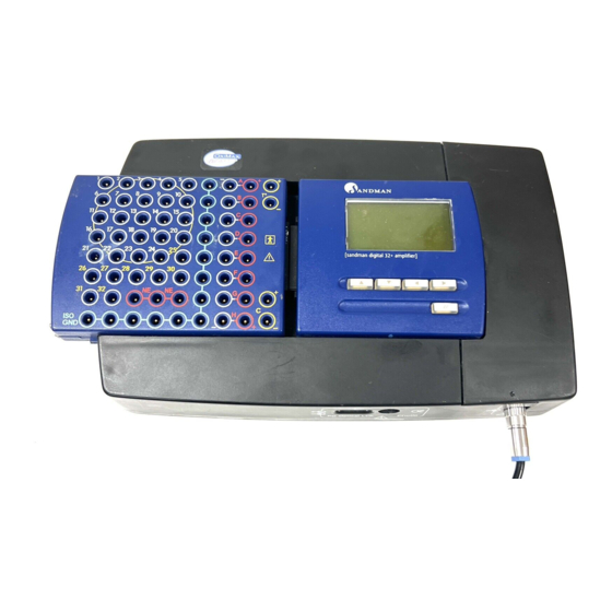
Page 19: Amplifier
SD32+ System Introduction 3.3. amplifier The SD32+ amplifier has two sockets, five ports, a graphic LCD display, and five menu control buttons as illustrated in Figure 6. SD32+ amplifier’s external connections (front) and Figure 7. SD32+ amplifier’s external connections (back). Figure 6. -
Page 20: Ports
When the Patient Box Link port is not in use replace the plastic cover provided to prevent dust build up on this connector. Optical Link Port – This port connects the amplifier to the Sandman elink Adapter using a fiber optic cable. -
Page 21: Lcd Display
The screen powers down again twenty seconds after the last button is pressed. After a montage in the Sandman Elite software has been selected, the LCD screen provides the following menu options: Impedance Check, Montage Setup, Digital Display, and Channel Display. -
Page 22: Integrated Pulse Oximeter
The integrated pulse oximeter calculates oxygen saturation (SpO ) and heart rate (HR) data collected using an approved sensor. The Sandman Elite software receives this data and displays it on the computer monitor. The pulse oximeter’s accuracy depends on the sensor used with the device. For some sensors, the accuracy of neonatal data may differ from that of adult data. -
Page 23: Sandman Elink™ Adapter
Sandman elink™ 3.6. adapter The Sandman elink adapter serves as a bridge to “link” the SD32+ amplifier to the computer. This enables the computer to send programming commands to, and receive sleep study data from, the SD32+ amplifier. The following figures show the Sandman elink adapter: Figure 8. -
Page 24: Power Supply
3.7. power supply 3.7.1. external medical grade ac/dc adapter Figure 10 shows the AC/DC Adapter that is specified for use with the Sandman elink adapter and, in turn, the SD32+ system. When connected to the Sandman elink adapter’s “DC In” socket, power from this device is passed to the SD32+ amplifier via the “DC Out”... -
Page 25: Amplifier Power Modes
3. Plug the adapter back into the wall socket. After you reset the fuse the Sandman elink Adapter should power up normally, if it does not, reset the fuse again. If after repeated resets the Sandman elink still does not power up you should contact Embla Technical Support for assistance. -
Page 26: Inputs
DCX socket is a 1/8” male mono connector. The eight input sockets allow the unit to accept DC inputs from multiple beds simultaneously. For example, the Sandman Elite software could be programmed so that sockets “DC X1” to “DC X4” accept inputs from bed one DC devices and sockets “DC X5”... -
Page 27: Software Driver Installation
® ® on your computer that is compatible with the Sandman Elite software. For more information about supported operating systems, consult your Sandman Elite User Manual. In most cases, a qualified representative from Embla Systems will install your amplifier and... -
Page 28: Amplifier System Assembly
Insert the opposite end of the fiber optic cable into the Optical Link connector on the Sandman elink Adapter until you hear or feel it click into place; the plug will only fit into the port one way. -
Page 29: Connecting The Dc Expansion Box To The Computer (Serial Connection)
Plug the mouse or keyboard PS2 plug into socket D of the SD32+ amplifier DC Expansion Box Cable. Changes must also be made to the Sandman software configuration so that the software can detect the DC expansion box. Please contact Embla Technical Support. -
Page 30: Figure 14. Typical Sd32+ System Set-Up
SD32+ Amplifier System Assembly System Figure 14. typical SD32+ system set-up... -
Page 31: Calibration
System record calibration is performed at the beginning and at the end of every study. Under the control of the Sandman Elite software, the amplifier generates a standard 50μV square-wave signal for calibration. This calibration is important for verifying filter and gain settings and for setting... -
Page 32: Maintenance
Check the connectors on the ends of the cables for bent or broken pins. Replace any cable that has a damaged connector. Check the connectors on the amplifier, headbox, and Sandman elink Adapter for broken or damaged contacts. If any are found, return the unit to Embla Technical Support for servicing or... -
Page 33: Cleaning
To obtain maintenance or cleaning information for equipment connected to the SD32+ that is not produced by Embla Systems, such as sensors, computers, monitors, printers, or other accessories, consult the manual supplied with the equipment. -
Page 34: Specifications
SD32+ Specifications System 8. Specifications 8.1. system specifications Description Active, non-invasive, medical device. Intended Use Amplifier Module for the acquisition (capture, conditioning, A/D conversion and transferring to a host system) of bioelectric signals produced by the human body Classification According to Class II b MDD 93/42/EEC Safety Standard... -
Page 35: Environmental Operating Conditions
A/D Conversion 2’s complement 24 bit Sigma-Delta A/D (16 bits actually transferred to host) Amplifier – PC Interface Sandman elink Adapter (by means of a fiber optic link) Other Interfaces 128x64 graphic LCD display and 5 push buttons Power Supply... -
Page 36: Filters
SD32+ Specifications System 8.4.2. filters High-Pass Filters Channels A to H and 1 to 32 Either DC or 0.099 Hz first order filter Low-Pass Filters Frequency cutoff at -3dB: 0.488 x sampling rate (A/D Converter at -6dB: 0.500 x sampling rate Output) 80 dB f ≥... -
Page 37: Sampling Rate
SD32+ System Specifications 8.4.4. sampling rate max sampling rate Number of Simultaneously Acquired Channels Maximum Sampling Rate 1 to 16 32768 Hz 16 to 32 16384 Hz 32 to 40 8192 Hz Selectable Sampling Rate 128,256,512… 32768 Hz (according to the limit of the maximum sampling rate) sampling skew All acquired channels will be sampled simultaneously (no sampling skew) -
Page 38: External Medical Grade Ac/Dc Adapter Specifications
SD32+ Specifications System 8.6. external medical grade AC/DC adapter specifications You can use either of the following AC/DC power adapters (D.2101) with the Sandman elink Adapter: 8.6.1 AULT SW173 Manufacturer AULT inc. Model SW173 Input 100-240VAC - 50/60Hz Output 15VDC @ 2.2A... -
Page 39: Dc Expansion Box Specifications
SD32+ System Specifications ® Sandman elink 8.7. ™ adapter Part Number 4200036 Case Materials: ABS plastic Dimensions: 137 x 200 x 8 mm Weight: 0.2 Kg Power supply AULT SW173 or SINPRO MPU50-106 Interfaces: HP 100 Mb fiber-optic Transmitter and Receiver RJ45 for Ethernet 100 bT Network link. -
Page 40: Environmental Conditions
SD32+ Specifications System 8.8.2. environmental conditions Usage Temperature +5 °C to +40 °C Relative Humidity 30% / 75% RH Atmospheric Pressure 700 / 1060 hPa Storage Temperature -30 °C to +60 °C (relative humidity up to 95% non- condensing Pressure 500 / 1060 hPa) Max 15 weeks 8.9. - Page 41 SD32+ System Index Index A E L AC/DC adapter · 16 extension cable · 12, 24 LCD control buttons · 15 connection · 24 LCD display · 15 active mode · 21 about · 17 F amplifier channel display · 18 calibration ·...
- Page 42 · 8 T radio frequency instruments · 7 Sandman elink Adapter · 10 reference sockets · 13 Sandman Elite software · 10, 17, relative humidity · 6 technical support · 21, 23 18, 27 removable patient box link · 24 temperature ·...
- Page 43 *4280034* REF: 4280034...
Need help?
Do you have a question about the Sandman and is the answer not in the manual?
Questions and answers