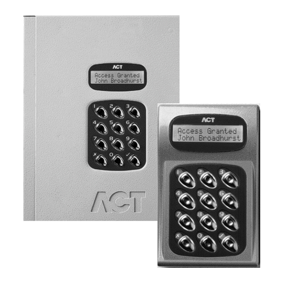
ACT Technology ACT ACT1000 Operating & Installation Instructions Manual
Access control units
Hide thumbs
Also See for ACT ACT1000:
- Installation instructions (2 pages) ,
- Operator instructions (2 pages)
Table of Contents
Advertisement
Quick Links
Advertisement
Table of Contents

Related Manuals for ACT Technology ACT ACT1000

Summary of Contents for ACT Technology ACT ACT1000
- Page 1 Instrucciones de funcionamiento e instalación de las unidades de control del acceso ACT Instrucciones de funcionamiento e instalación de las unidades de control del acceso ACT Operating & Installation Instructions for ACT1000/2000 Access Control Units Downloaded from: http://www.guardianalarms.net...
-
Page 2: Table Of Contents
Normalise Door ........ - Page 3 ACT2000 Configuration Standalone ......21 DS100 Door Station Installation ......……. 22 Wiring for Entry / Exit Readers .
-
Page 4: Default Code
ACT1000/2000 Operating Instructions Operating Instructions for ACT1000/2000 Access Control Units All user functions are accessed via two six-digit codes. The first code is for the Operator who is responsible for the day-to-day administration of the system, adding and deleting users, setting names and assigning time-zones etc. -
Page 5: Operator Menu
Change the PIN used to access the operator menu Change PIN Exit from the menu is automatic if no keys are pressed for a period of time. On the ACT2000, you will first be prompted for a door. Only present on ACT2000 Operator Menu... -
Page 6: User Setup
Activate O/P 3 duration when this user is granted access. Toggle Relay When the user is granted access, the relay is toggled so the door will remain permanently open until the next time the card or token is read. Note: The options assigned to an individual user operate in addition to those assigned to the group. -
Page 7: Assign Pins
The user must then present the first card in the batch to the reader at the selected door. When the user presents the first card to the reader, the card number is displayed. -
Page 8: One-To-One
When a group is selected, the combinations will be displayed on the top line of the display in the form ABCDEFGH + -. The 0 key may be used to highlight one of these combinations and the bottom line of the display will show that timezone and door combination. Pressing the key allows the combination to be altered. -
Page 9: Assign Options
The general-purpose output OP3 is activated for its programmed duration when users in this group are granted access. Toggle Relay When the user is granted access, the relay is toggled so the door will remain permanently open until the next time the card or token is read. -
Page 10: Display Log
The event types that can be filtered are access granted, access denied, alarms (mains fail, tamper etc.), door events (exit button pressed etc.) and others. The 0 key advances to each event type, and the key enables or disables the displayed event type. -
Page 11: Control Door
Lock Door The Lock Door function causes the door relay to be de-energized. The bottom line of the display will show “Door Locked” and the red LED on the reader will flash. All subsequent cards will be rejected until the door is unlocked or returned to its normal state. -
Page 12: Clear All (Act2000 Only)
ACT1000/2000 Operating Instructions Software Version 3.23-00 Clear All (ACT2000 Only) This function manually removes all users from the area. An event is logged for tracking. This is typically used at the end of a day or week to remove any users from the system who have neglected to use their cards when exiting. -
Page 13: Set Holidays
ACT1000/2000 Operating Instructions 1) Select Timezone 2) Select period 3) Changing days/holidays 4) Changing time period In addition, the timezone may be assigned a name or all time periods cleared quickly by highlighting and selecting the * or – symbols respectively: 5) Assigning timezone name 6) Clearing a timezone The assigned name will be displayed in place of Timezone N whenever the timezone... -
Page 14: Issue Number
ACT1000/2000 Operating Instructions Software Version 3.23-00 Issue Number This option allows the user to set the current system issue level to a number between zero (default) and 255. Only cards that have an issue number greater than or equal to the system issue level will be granted access. -
Page 15: Installer Menu
Operation Alarms Feature present on ACT1000 only Feature present on ACT2000 only On ACT2000 you will first be required to select a door. Installer Menu PIN’s alone are used to gain access PIN Only Users 1-1/2000 may use random coded cards... - Page 16 Factory Defaults Feature present on ACT1000 only Feature present on ACT2000 only On ACT2000 you will first be required to select a door. Exit from menu is automatic if no keys are pressed for a period of time. Software Version 3.23-00...
-
Page 17: System Settings
PIN codes to be entered before the user is allowed to exit. The Second Door option allows an auxiliary door to be controlled on an ACT1000 unit. The User Limiting option will prevent access to tracked users when the user limit is reached. -
Page 18: Fire Doors
This function allows a group of doors (or all doors) to be configured for fire override. A 0Volt signal from a fire alarm (or other) system is applied to the AUX input on door 1. This maintains normal operation. When the 0Volt signal is removed, the selected doors are held open until the 0Volt signal is re-applied. -
Page 19: Door Settings
The Locksaver (anti-tailgate) option truncates the relay timer when the door opens. This ensures that the door will be locked as soon as it closes even if a very long relay time is programmed. This also prevents overheating of the lock solenoid. -
Page 20: Timers
The door timers menu allows the installer to program the time delays for the relay, AUX output, open collector outputs OP2 and OP3 and the door ajar alarm time. Each timer may be programmed with a duration from 1 to 999 seconds seconds, which will operate the relay for a quarter of a second approximately. -
Page 21: High Speed
This menu is where additional door stations or ACT1000 units are configured as extra doors on the ACT2000 controller. The new door (Door 3 to 16) is selected using the 0 key and the current status of the door is displayed on the bottom line of the LCD. The... -
Page 22: Site Code 1
ACT1000/2000 Operating Instructions Site Code 1 This function allows the 8-digit site primary code for the system to be entered. The controller will recognize only cards with a matching site code. This code should also be quoted whenever additional cards or tags are being ordered for this installation. The factory default site-code is 10-2770-09, which allows the use of the test card supplied with the controller. -
Page 23: Diagrams
Card or Proximity Reader Volt Free Tamper Contacts Typical ACT1000 Configuration (Standalone) SENSE PUSH BUTTON CLOCK DOOR CONTACT DATA INTER LOCK GREEN BATCH: 96XX-1 PRODUCT: ACT 1000 REV1.1 SERIAL NUMBER: 00XXXX 0 1 2 3 4 5 6 7 8 9 OMRON... -
Page 24: Act2000 Configuration Standalone
Door 2 Release Button INPUT DOOR CONTACT PUSH BUTTON 5A 250VAC 5A 30VDC Door 2 Contact AUX RLY 2 RELAY 2 Door 2 Note: If the Mains Present or Door Contact inputs are not used, they should be linked to 0V... -
Page 25: Ds100 Door Station Installation
Always Place Varistor Across Lock Terminals Power +12V Supply Unit Note: If the Mains Present or Door Contact inputs are not used, they should be linked to 0V This illustration shows wiring for a normally de-energised To set the door number, lock. -
Page 26: Wiring For Entry/Exit Readers
Wiring for Entry/Exit Readers Card / Proximity or Pin Reader (Entry) Card or Proximity Reader (Exit) Wire both readers in parallel but leave the SENSE line on the Exit reader unconnected. For Wiegand Exit readers Connect DATA 0 of the exit reader to SENSE on the controller. -
Page 27: Act20 Pin Pad Installation Diagram
Connect to 12Vdc Cable: 8 Core Screened, Max 30m BUZZER SENSE UNUSED Controller Sense Clock Data Red LED Grn LED +12V Page 24 of 32 Controller Cable ACT20 White Buzzer Green Blue Black Brown Door Contact Yellow Push Button Orange +12V... -
Page 28: Act1000/2000 Cable Connections
ACT1000/2000 Cable Connections Direct Connection Cable (PC to Controller) DB25 Female (Rear View) 1 2 3 4 5 DB9 Female (Rear View) 6 7 8 9 Max cable length is 5m using standard alarm cable or 30m using twin twisted-pair (use 0V in each pair) Serial Printer Cable DB25 Male (Rear View) -
Page 29: Interlock Configuration
Door 3 The diagram above shows how to interlock 2 doors. When Door 3 is open, Door 4 is locked and vice versa. Remember to set Interlock for each door to Yes (See Installer Menu > Door Settings > Operation). -
Page 30: Actwinpro Configuration
ACTWinPro Configuration NETWORK B 0V GREEN ACT2000 Click here to Connect Select if Serial Port or Modem or TCP/IP Connection Direct Connect Cable From the Installer Menu, do the following: 1. Factory Default the controller. 2. Go to the Communications menu and Set Address. If there is only 1 controller, set the address to 1. -
Page 31: Act 4-Line Network Wiring
+BAT- C = SHIELD All lines are equivalent and operate in parallel Any controller may be connected to any line. To next door ACT 1000 Each line may be up to 1.4km in length and connect up to 32 controllers... -
Page 32: Act Single Line Rs-485 Converter
ACT Single Line RS-485 Converter 12V DC Power Supply (300mA) +12V Function +12V 0V & Shield RS-485 Bus NETWORK A B 0V ACT 2000 1. From the Controller keypad Enter Installer Menu->Communications and set a unique address for each controller on the network. Set Direct Connect to No. 2. -
Page 33: Act Modem Configuration
Direct Connection from Modem to Controller NETWORK B 0V ACT 2000 Max cable length is 5m using standard alarm cable or 30m using twin twisted-pair (use 0V in each pair) Modem Connection for ACT Network ACT Nework Interface Card RS485 RS485 232 Interface Converter... -
Page 34: Act Lan Configuration
ACTLAN Configuration Diagram Connections for 25 Way male Connector DB25 Male (Rear View) Connections for Direct Connect Max cable length is 5m using standard alarm cable or 30m using twin twisted-pair (use 0V in each pair) NETWORK B 0V ACT 2000 1. -
Page 35: System Diagram
RS232 Modem DS100 PSTN Door Modem RS232 Door Door DS100 DS100 Door Door System Diagram: Illustrating some of the ways to connect ACT Controllers to a computer. ACT System Diagram ACTWinPro RS232 Door 2000 Door DS100 Door 4 Line Interface Converter RS485 Line 1 (Max length 1.4km)
Need help?
Do you have a question about the ACT ACT1000 and is the answer not in the manual?
Questions and answers