
Related Manuals for Enecsys Single Repeater

Summary of Contents for Enecsys Single Repeater
- Page 1 Enecsys Micro-Inverters Single Repeater User Manual Version 1.0...
-
Page 3: Table Of Contents
When to install an Enecsys Repeater Installation Attaching the internal antenna Mounting the Enecsys Repeater Wall mounting the Enecsys Repeater (adhesive pad method) Wall mounting the Enecsys Repeater (screw fixed method) Mounting with a cable tie Turning the Enecsys Repeater on... - Page 4 Single Repeater Installation Manual Intelligent Reliable Power © ENECSYS 2010. All rights reserved.
-
Page 5: Introduction
Monitoring also allows the end-user to see the performance of any module at any time of the day. An Enecsys Repeater acts as a bridge between the Micro-inverter and the Gateway in situations where a sufficient communication link cannot be established. -
Page 6: Conventions Used In This Manual
Caution statements should be followed at all times. Attention: Attention statements are used to indicate where a part of the process or instrument has a special requirement. Attention statements should be followed at all times. © ENECSYS 2010. All rights reserved. -
Page 7: Safety
• There are no user serviceable parts inside this unit. • There are no replaceable or re-chargeable batteries contained within the Enecsys Repeater. • Do not attempt to open the unit. Tampering with the Enecsys Repeater may result in electri- cal shock or death. -
Page 8: Parts List
Single Repeater Installation Manual Intelligent Reliable Power 1.3 Parts List Although each separate installation from Enecsys is fully customisable and may differ, there are certain elements within each scope of delivery that will be consistent. 1 x Enecsys Repeater. 1 x Fixed antenna. -
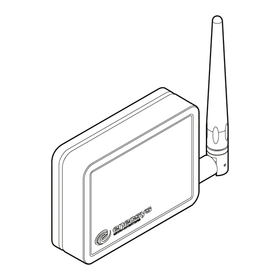
Page 9: Enecsys Repeater
Intelligent Reliable Power 1.4 Enecsys Repeater The Enecsys Repeater is designed to provide a ‘hop’ between nodes in the network. It is intended that the Enecsys Repeater be used to allow communication between the Inverters and Gateway where the propagation losses are too high for a reliable communication link within the installation. - Page 10 Double Repeater. When installing a repeater the Gateway should be placed into installer mode. PV MODULE INITIAL REPEATER LOCATION ATTIC 1st FLOOR SECOND REPEATER LOCATION GATEWAY GROUND FLOOR FIGURE 2. Internal Gateway and Repeater placement. © ENECSYS 2010. All rights reserved.
-
Page 11: Installation
Enecsys Repeaters are employed to improve the communication link between the inverters and the Gateway. The Enecsys Repeater is a 'plug and play' device; it is quickly and easily installed. The Enecsys Repeater should be installed within the roof-space of the building and positioned within easy connection distance of a mains supply AC power source. -
Page 12: Attaching The Internal Antenna
2.1 Attaching the internal antenna Attach the antenna to the RP SMA connector on the right hand side of the Enecsys Gateway. 1. Attach the antenna to the lower RP SMA plug on the right hand side of the Repeater, screw the antenna into place in a clockwise direction. -
Page 13: Mounting The Enecsys Repeater
If choosing a free standing installation place the Enecsys Repeater within reach of an AC mains power source. It is recommended that the Enecsys Repeater be placed as high as possible within the building roof-space. -
Page 14: Wall Mounting The Enecsys Repeater (Adhesive Pad Method)
1. Ensure that the back-plate of the Enecsys Repeater and the wall or mounting surface is clean from dust and grease. 2. Attach the antenna to the RP SMA plug on the right hand side of the Enecsys Repeater, screw the antenna into place in a clockwise direction. -
Page 15: Wall Mounting The Enecsys Repeater (Screw Fixed Method)
The screw fixing points are shown in Figure 5 on page 1. Attach the antenna to the RP SMA plug on the right hand side of the Enecsys Repeater, screw the antenna into place in a clockwise direction. 2. Connect the supplied external 5V DC plug top power supply to a mains supply AC power source. -
Page 16: Mounting With A Cable Tie
There may be situations where it is not possible to mount the Enecsys Repeater using the screw fixed or adhesive pad method. A cable tie can be utilised to fix the Enecsys Repeater to an internal pillar or suitable structure. -
Page 17: Turning The Enecsys Repeater On
To turn the Enecsys Repeater on feed the power cable through the power cable conduit, attach the 5V DC power supply jack-plug from the power port on the reverse of the Enecsys Repeater. 5V DC IN FIGURE 7. -
Page 18: Turning The Enecsys Repeater Off
To turn off the Enecsys Repeater remove the 5V DC power supply jack-plug from the power port on the reverse of the Enecsys Repeater. If the Enecsys Repeater is attached to its mounting surface, and the jack-plug is not easily accessible, disconnect the external 5V DC power supply from the AC mains supply. -
Page 19: Technical Specification
Input: 100-240V AC 50-60Hz 0.3A. Output; 5V DC, 1.2A. with 2.1mm jack. Table 1: Power adapter. Operating Temperature Temperature range 0°C to +55°C. Table 2: Operating temperature. Warranty Warranty 12 months. Table 3: Life expectancy. © ENECSYS 2010. All rights reserved. - Page 20 Fixed Antenna Radiating element 1/2 Wave Element. Frequency range 2.4 GHz. Peak gain 2.0 dBi. Polarisation Linear. Return loss -13 dB. Power rating 10W. Connector N Type. Dimensions 139 x 13mm. Table 4: Fixed antenna. © ENECSYS 2010. All rights reserved.
-
Page 21: Compliance
Single Repeater Installation Manual Intelligent Reliable Power 4. Compliance Enecsys Repeaters and their associated apparatus conform to the following compliance codes. IC: 9052A-REPEAT01 Operation is subject to the following two conditions: (1) this device may not cause harmful interference, and (2) this device must accept any interference, including interference that may cause undesired operation of the device. -
Page 22: Printing
Please do not print this manual unless neccesary, if you print this manual please keep it in a safe place for future reference. If you intend to dispose of this manual please do so in thoughful manner and recycle it. © ENECSYS 2010. All rights reserved. -
Page 23: Notes
Single Repeater Installation Manual Intelligent Reliable Power 6. Notes © ENECSYS 2010. All rights reserved. - Page 25 Enecsys Limited Harston Mill, Royston Road, Cambridge, CB22 7GG, UK. T: +44 (0) 1223 792 101 F: +44 (0) 1223 792 103 E: info@enecsys.com www.enecsys.com Registered Office: Enecsys Limited, 24 Hills Road, Cambridge, CB2 1JP, England. Registration No: 04832321...
Need help?
Do you have a question about the Single Repeater and is the answer not in the manual?
Questions and answers