Table of Contents
Advertisement
Advertisement
Table of Contents

Related Manuals for Astrid HALLEY E

Summary of Contents for Astrid HALLEY E
- Page 1 UPS OPERATING MANUAL PLANET E – HALLEY E...
- Page 3 UPS OPERATING MANUAL Index of sections Code 1 – UPS GENERAL DESCRIPTION AND INSTALLATION OM226130 2 – FRONT PANEL OM226131 3 – START-UP, SHUT-DOWN AND MANUAL BYPASS OM226132 Descrizione Data Emesso Controllato Approvato Lingua Pagina di Pag. Rev. Description Date Issued Checked Approved...
-
Page 4: Table Of Contents
Ups general description & installation UPS GENERAL DESCRIPTION AND INSTALLATION Index INTRODUCTION ................3 ENVIRONMENT.................... 3 1.1.1 ISO 14001 certification ................. 3 1.1.2 Packing....................3 1.1.3 Lead battery..................3 SAFETY RULES................... 3 1.2.1 Safety of persons ................. 3 1.2.2 Product safety ..................4 1.2.3 Special precautions................ - Page 5 Ups general description & installation RECEIPT OF THE UPS................11 HANDLING OF THE UPS ................11 POSITIONING AND INSTALLATION ............12 3.3.1 Base plan, static load and weights ............ 12 3.3.2 Dimensions and distances ..............13 ELECTRICAL CONNECTION ..............14 3.4.1 Terminal board ...................
-
Page 6: Introduction
Ups general description & installation INTRODUCTION 1.1 ENVIRONMENT 1.1.1 ISO 14001 certification The product was manufactured in a factory certified ISO 14001 respecting eco- design rules. 1.1.2 Packing UPS packing materials must be recycled in compliance with all applicable regulations. 1.1.3 Lead battery This product contains lead-acid batteries. -
Page 7: Product Safety
Ups general description & installation 1.2.2 Product safety A protection circuit breaker must be installed upstream and be easily accessible. Never install the UPS near liquids or in an excessively damp environment. Never let a liquid or foreign body penetrate inside the UPS. Never block the ventilation grates of the UPS. -
Page 8: Ups General Description
Ups general description & installation UPS GENERAL DESCRIPTION 2.1 TYPOLOGY All UPS covered by this manual are on-line, double conversion; the inverter supplies always energy to the load, whether mains is available or not (according to the battery autonomy time). WARNING The UPS output is energized even during mains failure, therefore in compliance with the prescriptions of EN 50091-1, the installer will have to identify the line or the plugs... -
Page 9: System Description
Ups general description & installation 2.2 SYSTEM DESCRIPTION 2.2.1 Rectifier It converts the three phase voltage of the mains into continuous DC voltage. It uses a three phase 6 pulses fully-controlled thyristors bridge. It’s designed to supply the inverter at full load and the battery at the maximum recharge current. -
Page 10: Inverter
2.2.4 Battery and battery charger On the PLANET E 20-30kVA and HALLEY E 20-30kVA UPS battery can be located inside the UPS for autonomy from 5 up to 15 minutes depending on the UPS power (see tables page 12);... -
Page 11: Manual Bypass
Ups general description & installation 2.2.6 Manual bypass It‘s used to by-pass the UPS, supplying the load directly to the mains in case of maintenance or serious failure. WARNING The sequence of bypass switching must be carried out with respect to the procedure indicated on the UPS and in the chapter “Start-up, shut-down and manual bypass”. -
Page 12: Operating Status
Ups general description & installation 2.3 OPERATING STATUS The following paragraphs show all the possible operating status of the UPS. 2.3.1 Normal operation The inverter is supplied by the rectifier; the load, through the static switch, is supplied directly by the inverter output. Picture 4 - Normal operation 2.3.2 Load supplied by bypass due to inverter fault The load is transferred to bypass through the static switch;... -
Page 13: Rectifier Failure Or Mains Failure
Ups general description & installation 2.3.3 Rectifier failure or mains failure The inverter is supplied by the battery for the required autonomy time; the load, through the static switch, is supplied directly by the inverter output. Picture 6 - Rectifier failure or mains failure 2.3.4 Manual bypass The load is supplied by the mains through the manual bypass;... -
Page 14: Installation
Ups general description & installation INSTALLATION 3.1 RECEIPT OF THE UPS When the UPS is received, please attend immediately to its unpacking and carry-out an accurate visual check to be sure that the equipment has not been damaged during transport. IMPORTANT In case of objections relating to damage incurred during transport these must be immediately notified to the transportation company after receipt of the equipment. -
Page 15: Positioning And Installation
Ups general description & installation 3.3 POSITIONING AND INSTALLATION The UPS must be installed in a clean and dry room, preferably not dusty. The User must ensure that there is enough air exchange in the room so that the equipment can be adequately cooled;... -
Page 16: Dimensions And Distances
Ups general description & installation 3.3.2 Dimensions and distances Picture 10 - Dimensions and distances from the walls UPS (kVA) 1Ph e 3Ph L – mm P – mm H – mm 1345 X (min.) – mm Y (min.) – mm ADD. -
Page 17: Electrical Connection
Ups general description & installation 3.4 ELECTRICAL CONNECTION The electrical connection is part of the work which is normally provided by the supplier that carries out the electrical installation and not by the UPS manufacturer. For this reason, the following recommendations are only an indication, as the UPS manufacturer is not responsible for the electrical installation. -
Page 18: Terminal Board
Ups general description & installation 3Ph UPS (kVA) Rectifier 3x50 3x80 3x100 3x150 3x150 Input fuses (A) Bypass 3x150 3x200 3x200 Rectifier 4x10 4x25 3x35 3x50 3x70 Input cables (mm Bypass 4x35 4x50 4x70 4x10 4x25 4x35 4x50 4x70 Output cables (mm 2x16 2x25 2x50... -
Page 19: Battery Connection And Positioning
Ups general description & installation 3.5 BATTERY CONNECTION AND POSITIONING IMPORTANT For battery installation please respect the EN62040-1-2 prescriptions, paragraph 4.9.20, and at the same time all the national rules or specifications which can be applied to the premises or building. To obtain the battery life indicated by the battery manufacturer, the operating temperature must remain between 0 and 25 °C. -
Page 20: Picture 14 - Wiring 4 Batteries For Tray
Ups general description & installation Picture 14 - Wiring 4 batteries for tray Picture 15 - Wiring 8 batteries for tray The configurations and the quantity of battery traies mounted on the UPSs are shown in the following table: BATTERY TRAIES UPS 1Ph e 3Ph QUANTITY TYPE... -
Page 21: External Battery
Ups general description & installation 3.6 EXTERNAL BATTERY The external battery is used to increase the UPS autonomy time during mains failure. It’s always provided for UPS’s having ratings >30KVA IMPORTANT With an external battery, the internal battery isn’t necessary. The external battery, (consisting of 32 battery blocks maximum, with 6 cells each for 192 cells total), are installed in two different cabinets : - AS028 for 38Ah battery blocks... -
Page 22: Picture 17 - Dimensions Of The External Battery Cabinets
Ups general description & installation Picture 17 - Dimensions of the external battery cabinets CABINET AS028 AS029 L – mm P – mm H – mm 1150 1340 L1 – mm P1 – mm L2 – mm CABINET AS028 AS029 Weight w/o battery –... -
Page 23: Connections
Ups general description & installation 3.6.2 Connections The following picture shows the electrical connection between the UPS and the external battery cabinet. Picture 18 - Battery cabinets connections The connection cables are two power cables, with section of 50mm (see following table) and with length ranging from 2 to 50m. - Page 24 Front panel FRONT PANEL Index INTRODUCTION ................3 DESCRIPTION ..................4 MIMIC DESCRIPTION .................. 4 ALARMS AND OPERATING STATUS............5 LCD DISPLAY MANAGEMENT ............8 DEFAULT..................... 8 MAIN MENU ....................8 MEASURES ....................9 3.3.1 Output....................10 3.3.2 Bypass ....................10 3.3.3 Inverter ....................11 3.3.4 AC/DC ....................
- Page 25 Front panel Index of pictures Picture 1 - Front panel ........................3 Picture 2 - Menu structure......................... 18 OM226131 Rev. A...
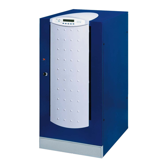
- Page 26 Front panel INTRODUCTION The front panel of the UPS, consisting of a double row alphanumeric display plus 5 function keys, allows the complete monitoring of the UPS status. The mimic flow helps to understand the operating status of the UPS. Picture 1 - Front panel OM226131 Rev.
-
Page 27: Description
Front panel DESCRIPTION 2.1 MIMIC DESCRIPTION Picture1 shows the mimic present on the display, with the names of the circuit breakers/isolator switches of the UPS. Also the led's and blocks that comprise the UPS are clearly identified. ⇒ LED 1 Lit-up green = Mains present at the rectifier input. - Page 28 Front panel 2.2 ALARMS AND OPERATING STATUS The alphanumeric display offers a complete diagnostic of the system by showing 25 alarms and 6 operating status descriptions. Each alarm is associated to a code that allows it to be stored in the events history. A1 MAINS FAULT = Rectifier input mains failure Possible causes: 1) Central system black-out (mains failure)
- Page 29 Front panel intermittent 2) Mains variation speed not acceptable for the UPS (for load protection reasons) A13 INV OUT TOL = Inverter output voltage out of tolerance Possible causes: 1) Intervention of the inverter current limitation for excessive load (more than 200%) 2) Inverter failure A14 OVERLOAD = Inverter overload (load exceeding 100%).
- Page 30 Front panel 3) Wrong positioning of the UPS (distance from walls, altitude) A22 BYP SWITCH = Closure of the commutation switch which forces the load to bypass (maintenance) A23 EPO BUS = Intervention of the emergency power off switch according to the EN50091-1 A24 CURR STOP = Inverter bridge stop for max current Possible causes: 1) Repeated short circuits at the UPS output...
- Page 31 The default screen appears on the LCD panel when the UPS is in normal operation (with no alarm present); it shows the name of the UPS (HALLEY E for example) the nominal power and the value of the output voltage.
- Page 32 Front panel 3.3 MEASURES The following pictures shows the structure of the MEASURES menu. OUTPUT measures. <NAME> xxx KVA <NAME> xxx KVA <NAME> xxx KVA <NAME> xxx KVA accessed pressing the key OUTPUT OUTPUT OUTPUT OUTPUT (see 3.3.1), pressing the keys the other sub-menu are scrolled down.
- Page 33 Front panel 3.3.1 Output Pressing the key the following OUTPUT VOLTAGE OUTPUT VOLTAGE OUTPUT VOLTAGE OUTPUT VOLTAGE parameter is shown, while the key XXX YYY ZZZ Volt XXX YYY ZZZ Volt XXX YYY ZZZ Volt XXX YYY ZZZ Volt leads to the previous screen. Pressing the key the following OUTPUT FREQUENCY...
- Page 34 Front panel 3.3.3 Inverter Pressing the key the following INVERTER VOLTAGE INVERTER VOLTAGE INVERTER VOLTAGE INVERTER VOLTAGE parameter is shown, while the key XXX YYY ZZZ Volt XXX YYY ZZZ Volt XXX YYY ZZZ Volt XXX YYY ZZZ Volt leads to the previous screen. Pressing the key the following INVERTER FREQUENCY...
- Page 35 Front panel Pressing the key the following BATTERY CURRENT TERY CURRENT TERY CURRENT TERY CURRENT parameter is shown, while the key XXX Ampere XXX Ampere XXX Ampere XXX Ampere leads to the previous screen. Pressing the key the following AUTONOMY AUTONOMY AUTONOMY AUTONOMY...
- Page 36 Front panel 3.4 ALARMS This menu, when selected, shows the status of the equipment and the current alarms are shown (see list below). Each time an alarm occurs, the display goes to this menu to indicate the alarms present; the audible alarm can be silenced pressing the key .
- Page 37 Front panel 3.4.2 History Pressing the key the following RET TO EXIT HISTORY RET TO EXIT HISTORY RET TO EXIT HISTORY RET TO EXIT HISTORY alarm is shown; pressing the key 1st alarm/status 1st alarm/status 1st alarm/status 1st alarm/status exit the history, leading to the ALARMS menu screen (see 3.4).
- Page 38 Front panel 3.4.3 List of alarms and status List of alarms List of status MAINS FAULT AC/DC OK CHARGER FAULT RECT FUSE AC/DC FAULT INP WR SEQ BCB OPEN BATT OK BATT DISCH BATT AUT END A10 BATT FAULT A11 BATT IN TEST A12 PLL FAULT INV SYNC A13 INV OUT TOL...
- Page 39 Front panel 3.5 SPECIAL IMPORTANT When entering the SPECIAL menu a password is required, as the operations which are allowed needs to be carried out by competent personnel. For each operation a confirmation is required. Password entering; if wrong the PASSWORD PASSWORD PASSWORD...
- Page 40 Front panel 3.5.1 Reset This menus provides a general PRESS RESET PRESS RESET PRESS RESET PRESS RESET reset of the UPS status pressing TO RESET UPS TO RESET UPS TO RESET UPS TO RESET UPS the key . Pressing another key exit the menu.
- Page 41 Front panel 3.6 MENU STRUCTURE Picture 2 - Menu structure OM226131 Rev. A...
- Page 42 Start-up, shut-down & manual bypass START-UP, SHUTDOWN & MANUAL BYPASS Index INTRODUCTION ................2 START-UP PROCEDURE ..............2 SHUT-DOWN PROCEDURE (LOAD NOT SUPPLIED ).....3 MANUAL BY-PASS PROCEDURE ............3 START-UP FROM MANUAL BY-PASS ..........4 Descrizione Data Emesso Controllato Approvato Lingua Pagina di Pag. Rev.
- Page 43 Start-up, shut-down & manual bypass INTRODUCTION Before carrying out whatever procedure described in this chapter, read carefully the instructions, in order to avoid possible damages to persons or thing due to wrong manoeuvre. START-UP PROCEDURE For the UPS start-up, proceed as follows. WARNING Before switching on the UPS, make sure: 1) the emergency power off “EPO”...
- Page 44 Start-up, shut-down & manual bypass SHUT-DOWN PROCEDURE (LOAD NOT SUPPLIED ) Nr. ACTION LCD DISPLAYING UPS OPERATION Open OCB A19 OCB OPEN The supply to the load is interrupted. LED #7 lit orange Open BCB A7 BCB OPEN The battery is disconnected from the rectifier.
- Page 45 Start-up, shut-down & manual bypass START-UP FROM MANUAL BY-PASS Before the start-up from manual by-pass (after a maintenance or repairing) check that the “NORMAL-BYPASS” switch is in BYPASS position. LCD DISPLAYING ACTION UPS OPERATION BLANK Close RCB UPS START UP The rectifier is supplied and the DC voltage increases up to the nominal WAIT PLEASE...
- Page 46 FACTORY & HEAD OFFICE Viale Europa, 22 - Loc. Ponte d’Arno 52018 CASTEL SAN NICCOLO’ (AR) Phone: +39-0575-500026 Fax: +39-0575-500032 http://www.astridups.it...
Need help?
Do you have a question about the HALLEY E and is the answer not in the manual?
Questions and answers