Table of Contents
Advertisement
Quick Links
Advertisement
Table of Contents

Related Manuals for SOYO LI-7000


Summary of Contents for SOYO LI-7000
- Page 1 SOYO LI-7000 LPX SYSTEM **************************************************** Socket 370 Celeron Processor supported FW82810 AGP/PCI/AMR Chipset 66/100 MHz Front Side Bus supported Custom LPX Form Factor **************************************************** User's Manual...
- Page 2 It is the policy of Soyo Computer Inc. to respect the valid patent rights of third parties and not to infringe upon or to cause others to infringe upon such rights.
-
Page 3: Table Of Contents
Table of Contents LI-7000 Table of Contents CHAPTER 1 INTRODUCTION..............1 KEY FEATURES .............1 LI-7000 SYSTEM ILLUSTRATION ........1 UMPACKING ..............4 CHAPTER 2 MOTHERBOARD DESCRIPTION ........5 INTRODUCTION ............5 KEY FEATURES .............5 HANDLING THE MOTHERBOARD ......7 ELECTROSTATIC DISCHARGE PRECAUTIONS ..7 SY-7IWL-T MOTHERBOARD COMPONENTS .....8 CHIPSET ...............10... - Page 4 Table of Contents LI-7000 SOYO COMBO SETUP..........51 STANDARD CMOS SETUP ..........55 ADVANCED BIOS FEATURES........58 ADVANCED CHIPSET FEATURES......62 INTEGRATED PERIPHERALS ........64 POWER MANAGEMENT SETUP ........68 PNP/PCI CONFIGURATION SETUP......71 PC HEALTH STATUS............74 LOAD OPTIMIZED DEFAULTS........76 4-10 LOAD FAIL-SAFE DEFAULTS........77 4-11 SUPERVISOR PASSWORD...........78 4-12 USER PASSWORD............79...
-
Page 5: Chapter 1 Introduction
1 x FDD, 1 x HDD (hidden), 1 x CD-ROM drive bay Ø Detachable Drive Bracket Ø Riser Card for 1 x PCI and 1 x AMR slot Expansion 1-2 LI-7000 SYSTEM ILLUSTRATION Figure 1. Front Panel Floppy Drive Mounting Bay Power Button CD-ROM Mounting Bay... - Page 6 Introduction LI-7000 Figure 2. Back Panel Game Port Serial Port Keyboard LINE-OUT Mouse Parallel Port TV-OUT S-OUT VGA Port Figure 3. Inside Look 150W SFX Power Supply CD-ROM Riser Card Socket 370 CPU...
-
Page 7: Riser Card
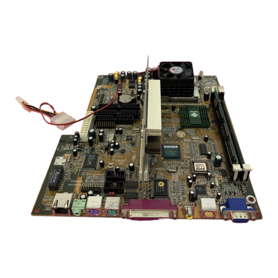
Introduction LI-7000 1. SY-7IWL-T Motherboard Layout ATX Power Connector Game Port LAN Chip Realtek 8139B LINE-OUT Front Panel Connector PS/2 KB Connector PS/2 Mouse Lithium Connector Battery Buzzer CODEC COM1 COM2 AC97 IDE 2 IDE 1 PCI Slot CMOS Clear... -
Page 8: Umpacking
When unpacking the System, check for the following items: u The LI-7000 System u The Quick Start Guide u The Installation CD-ROM u SOYO 3-in-1 Bonus Pack CD-ROM (Norton AntiVirus, Ghost and Virtual Drive) u Power Cord Like most electronic equipment, your Motherboard and other components and devices may be damaged by electrostatic discharge. -
Page 9: Chapter 2 Motherboard Description
Auto detect CPU bus Frequency (66/100) Ø Auto-detect CPU voltage Ø Chipset integrated 3D AGP Accelerator Ø Easy CPU settings in BIOS with the “SOYO COMBO Setup” Ø PC98, ACPI Ø Ultra DMA33/66 (ATA 33/66) Ø Supports ACPI Suspend Indicator Ø... - Page 10 Motherboard Description LI-7000 Ø Fan speed control Ø Battery Low voltage Detect Ø Support 7 sets of voltage monitoring Ø Supports multiple-boot function Ø Y2K Complaint Ø Supports Audio Modem Riser slot (AMR 1.0 compliant) Ø 1 x 32-bit bus mastering PCI slot Ø...
-
Page 11: Handling The Motherboard
Motherboard Description LI-7000 HANDLING THE MOTHERBOARD To avoid damage to your Motherboard, follow these simple rules while unpacking: Ø Before handling the Motherboard, ground yourself by grasping an unpainted portion of the system's metal chassis. Ø Remove the Motherboard from its anti-static packaging. Hold the Motherboard by the edges and avoid touching its components. -
Page 12: Sy-7Iwl-T Motherboard Components
Motherboard Description LI-7000 2-5 SY-7IWL-T MOTHERBOARD COMPONENTS F G H I... - Page 13 Motherboard Description LI-7000 Winbond W83627HF-AW LPC I/O Chip Power-On by Keyboard Jumper Game Port Connector COM1/COM2 Connector Realtek 8139B LAN Chip AC97 Codec Chip CD-IN Connector Front panel connectors Floppy Disk Drive (FDD) Port ATX Power Supply Connector Bus Mastering E-IDE/ATAPI Ports...
-
Page 14: Chipset
Motherboard Description LI-7000 2-6 CHIPSET To compliment the Intel ® Celeron processor, the Intel ® 810 chipsets delivers a balanced platform solution for value computing. The 810 chipset is a highly-integrated three-chip solution consisting of a Graphics & Memory Controller (Intel 82810), an I/O Controller (Intel82801), and a Firmware Hub (Intel 82802). - Page 15 Motherboard Description LI-7000 technology. The 82810 chip optimizes system memory arbitration, similar to AGP technology, resulting in a more responsive and cost-effective system. The 82810 Graphics Memory Controller Hub (GMCH) features Intel ® graphics technology and software drivers, using Direct AGP (integrated AGP) to create vivid 2D and 3D effects and images.
- Page 16 Motherboard Description LI-7000 The Integrated Audio-Codec 97 controller enables software audio and modem by using the processor to run sound and modem software. By reusing existing system resources, this feature adds flexibility, and improves sound quality. The 82802 Firmware Hub (FWH) stores system BIOS and video BIOS, eliminating a redundant nonvolatile memory component.
- Page 17 Motherboard Description LI-7000 efficient use of system memory for graphics, O/S and applications Ø Optional 4MB of dedicated display cache video memory Enables SKU differentiation with increased 3D graphics performance improvement over Direct AGP Ø Low-power sleep modes Energy Savings Ø...
- Page 18 Motherboard Description LI-7000 latency Demultiplexing of address and data on the bus for near 100 percent bus efficiency AC timing for 133 MHz data transfer rates, allowing real data throughput in excess of 500 MB/sec 2-6.2 Universal Serial Bus (USB) The motherboard has two USB ports;...
- Page 19 Motherboard Description LI-7000 2-6.3 IDE Support The motherboard has two independent bus-mastering PCI IDE interfaces. These interfaces support PIO Mode3, PIO Mode 4, ATAPI devices (e.g., CD-ROM), and Ultra DMA/33 synchronous-DMA mode transfers. The BIOS supports logical block addressing (LBA) and extended cylinder head sector (ECHS) translation modes.
-
Page 20: I/O Interface Controller
Motherboard Description LI-7000 2-6.4 Real-Time Clock, CMOS SRAM, and Battery The real-time clock is compatible with DS1287 and MC146818 components. The clock provides a time-of-day clock and a multicentury calendar with alarm features and century rollover. The real-time clock supports 256 bytes of battery-backed CMOS SRAM in two banks that are reserved for BIOS use. - Page 21 Motherboard Description LI-7000 program, there are four options for parallel port operation: Compatible (standard mode) Bi-directional (PS/2 compatible) Bi-directional EPP. A driver from the peripheral manufacturer is required for operation. See Section 6.2 for EPP compatibility. Bi-directional high-speed ECP 2-7.3 Diskette Drive Controller The I/O controller is software compatible with the 82077 diskette drive controller and supports both PC-AT and PS/2 modes.
-
Page 22: Audio Subsystem
Motherboard Description LI-7000 The keyboard controller also supports the hot-key sequence <Ctrl><Alt><Del>, software reset. This key sequence resets the computer’s software by jumping to the beginning of the BIOS code and running the Power On Self Test (POST). 2-7.5 Infrared Support The IR connection can be used to transfer files to or from portable devices like laptops, PDAs, and printers. -
Page 23: Wake On Lan Technology
Motherboard Description LI-7000 2-10 WAKE ON LAN TECHNOLOGY Wake on LAN technology enables remote wakeup of the computer through a network. The LAN subsystem, whether onboard or as a PCI bus network adapter, monitors network traffic at the Media Independent Interface. -
Page 24: Chapter 3 Hardware Installation
Motherboard’s Hardware Installation LI-7000 Chapter 3 MOTHERBOARD’ S HARDWARE INSTALLATION 3-1 PREPARATIONS Gather and prepare all the following hardware equipment to complete the installation successfully: u Celeron Socker370 processor with CPU cooling fan* u SDRAM module u Monitor u Keyboard... -
Page 25: Installation Guide
Motherboard’s Hardware Installation LI-7000 3-2 MOTHERBOARD INSTALLATION GUIDE We will now begin the installation of the Motherboard. Please follow the step-by-step procedure designed to lead you to a complete and correct installation. Warning: Turn off the power to the Motherboard, system chassis, and peripheral devices before performing any work on the Motherboard or system. -
Page 26: 3-2.1 Cpu Installation
Motherboard’s Hardware Installation LI-7000 3-2.1 CPU Installation To perform the installation of your new SY-7IWL-T Motherboard, follow the steps below: Record the working frequency of Mark your CPU Frequency: your CPU that should be clearly marked on the CPU cover. - Page 27 Motherboard’s Hardware Installation LI-7000 Seat the processor in the socket completely and without forcing. Then close the socket handle to secure the CPU in place. Remember to connect the CPU Cooling Fan to the appropriate power connector on the Motherboard. The fan is a key component that will ensure system stability.
-
Page 28: 3-2.2 Sdram Memory Module Installation
Motherboard’s Hardware Installation LI-7000 3-2.2 SDRAM Memory Module Installation DIMM 2 DIMM 1 Your board comes with two DIMM sockets, and supports up to 512MB main memory using industry standard Synchronous DRAM (SDRAM), single or double-sided, 3.3V unbuffered DIMM modules from 8MB to 256MB. - Page 29 Motherboard’s Hardware Installation LI-7000 Memory Configuration Table Number of Memory DIMM 1 DIMM 2 Modules Double-sided/ Double-sided/ Single-sided Single-sided Double-sided/ Double-sided/ Single-sided Single-sided RAM Type SDRAM¹ Memory Module Size (MB) 8/16/32/64/256 Mbytes Note: PC100 Compliant DIMM module is required regardless of 66 or...
-
Page 30: 3-2.3 Motherboard Connector
Motherboard’s Hardware Installation LI-7000 3-2.3 Motherboard Connector Pin -1 IDE 2 IDE 1 Secondary Primary 3-2.3.1 IDE Device Installation (HDD, CD-ROM) This Motherboard offers two primary and secondary IDE device connectors (IDE1, IDE2). It can support up to four high-speed ATA 33/66 HDD or CD-ROM. - Page 31 Motherboard’s Hardware Installation LI-7000 3-2.3.2 Floppy Drive Installation Pin -1 Floppy Drive Connector The system supports 5 possible floppy drive types: 720 KB, 1.2 MB, 1.44 MB, 2.88 MB, and LS-120. In addition, this Motherboard supports a 3-mode (720KB/1.2MB/1.44MB) floppy commonly used in Japan.
- Page 32 Motherboard’s Hardware Installation LI-7000 3-2.3.3 Front Panel Connections Front Panel Device : JP16 Power Button & Front Panel LED: JP15 Speaker: JP10 Front Panel Device: JP16 Plug the computer case's front panel board flat cable connector to this header. The header by out is as follows:...
- Page 33 Motherboard’s Hardware Installation LI-7000 To 7IWL-T Motherboard IR Module LINE-OUT MIC JACK LINE-IN (1). Universal Serial Bus USB1/USB2 This Motherboard provides two USB ports for your additional devices. Plug the USB device jack into the available USB connector USB1 or USB2.
- Page 34 Motherboard’s Hardware Installation LI-7000 Power Button & Front Panel LED: JP15 HDD LED IDEACT# PWRBTN#LPC SVS LED # Power Button ACPI LED 5VSB IOSVSB LED 0 LAN LED (1). IDE LED Attach the 2-pin IDE device LED cable to the corresponding IDE LED header on the Motherboard.
- Page 35 Motherboard’s Hardware Installation LI-7000 (3). ATX Power On/Off Switch Attach the 2-pin momentary type switch to the PWRBT header for turning On or Off your ATX power supply. PWRBT Pin Assignment Pin5 Pin7 5VSB PWRBTN#LPC (4). LAN LED Attach the 2-pin LAN LED connector to this header. The LED will light up when data is transfer over the network.
- Page 36 Motherboard’s Hardware Installation LI-7000 3-2.3.4 Back Panel Connections All external devices such as the PS/2 keyboard, PS/2 mouse, printer, modem, USB can be plugged directly onto the Motherboard back panel. Only after you have fixed and locked the Motherboard to the computer case can you start connecting the external peripheral devices.
- Page 37 Motherboard’s Hardware Installation LI-7000 1. LAN Connector This is the network connector, supporting 10/100MHz transfer rates. Make sure to use the right quality of cable, 100MHz operation requires special cable, ask you dealer. TX/RX LINK (10/100) NCRX- NC RX+ TX- 2.
- Page 38 Motherboard’s Hardware Installation LI-7000 4. PS/2 Mouse Similarly, plug the mouse jack directly into the 6-pin female PS/2 mouse connector. Pin5 Pin6 Mouse Clock Pin4 Pin3 Pin1 Pin2 Mouse DATA 5. Parallel Port PRT This parallel port is used to connect the printer or other parallel devices.
- Page 39 Motherboard’s Hardware Installation LI-7000 7. S-Video This output provides a S-Video signal for devices that support this standard. 8. VGA monitor connector Plug the monitor cable into the 15-pin female VGA connector located at the real panel of the motherboard.
- Page 40 Motherboard’s Hardware Installation LI-7000 3-2.3.5 Other Connections 1. Serial Port COM 1 and COM2 This Motherboard provides two serial port connectors. Plug the 9-pin end of the flat cable into the COM1/COM2 serial port header on the Motherboard, as shown in the figure below, then fix the connector to the rear panel of the computer case.
- Page 41 Motherboard’s Hardware Installation LI-7000 2. CD Line-in (J2,J3) This Motherboard provides two CD-Line in connectors. Please connect the 4-pin audio cable from your CD-ROM drive to either J2 or J3. (It fits in only one, depending on the cable that came with your CD-ROM drive)
- Page 42 CPUFAN connector on the Motherboard. The fan will stop when the system enters into Suspend Mode. (Suspend mode can be enabled from the BIOS Setup Utility, [Soyo Combo] menu.) To avoid damage to the system, install according to the following pin...
- Page 43 Motherboard’s Hardware Installation LI-7000 3-2.3.6 AGP VGA Card This motherboard comes with integrated AGP subsystem therefore, AGP VGA card is not needed. Other Display Cards: Insert other types of VGA cards into the PCI or ISA expansion slots according to card specifications.
- Page 44 Motherboard’s Hardware Installation LI-7000 Warning: Follow these precautions to preserve your Motherboard from any remnant currents when connecting to power supply: Turn off the power supply and unplug the power cord of the power supply before connecting to PW connector.
- Page 45 Motherboard’s Hardware Installation LI-7000 3-2.3.8 AMR (Audio Modem Riser) Connector This motherboard supports AMR (Audio-Modem Riser) slot that facilitates audio or modem riser card expansion. Since AC97 audio codec is built-in down on the motherboard, only “Secondary” mode modem riser (MR) card can be used on the AMR slot.
-
Page 46: 3-2.4 Jumpers Setting
Motherboard’s Hardware Installation LI-7000 3-2.4 Jumpers Setting 3-2.4.1 Enable/Disable Power-On by Keyboard (JP1) You may choose to enable the Power-On through Keyboard function by shorting pin 1-2 on jumper JP1; or short pin 2-3 to disable this function. Power-On by... -
Page 47: 3-2.5 Cmos Clearing (Jp5)
Motherboard’s Hardware Installation LI-7000 Make sure to set the AC line input appropriately based on the local electricity supply. Improper setting may cause the damage of the power supply or system. 3-2.5 CMOS Clearing (JP5) After you have turned off your computer, clear the CMOS memory by momentarily shorting pins 2-3 on jumper JP5, for a few seconds. -
Page 48: 3-2.7 Quick Bios Setup
This Motherboard does not use any hardware jumpers to set the CPU frequency. Instead, CPU settings are software configurable with the BIOS [Soyo Combo Feature]. The [Soyo Combo Feature] menu combines the main parameters that you need to configure, all in one menu, for a quick setup in BIOS. - Page 49 Step 2. Select [Load Optimized Defaults] Select the “Load Optimized Defaults” menu and type “Y” at the prompt to load the BIOS optimal setup. Step 3. Select [Soyo Combo Feature] (a) CPU Host/PCI Clock CPU Host / PCI Clock The PCI clock frequency depends on...
-
Page 50: 3-2.8 Troubleshooting At Fist Start
Motherboard’s Hardware Installation LI-7000 3-2.8 Troubleshooting at First Start What should I do if the Motherboard refuses to start? Check that all DIMM memory modules are inserted completely. Sometimes a DIMM that is not inserted properly can cause boot problems. -
Page 51: 3-2.9 Power Off
Motherboard’s Hardware Installation LI-7000 3-2.9 Power Off There are two possible ways to turn off the system: Use the Shutdown command in the Start Menu of Windows 95/98 to turn off your computer. Press the mechanical power-button and hold down for over 4 seconds, to shutdown the computer. -
Page 52: Chapter 4 Bios Setup Utility
Motherboard’s BIOS Setup Utility LI-7000 Chapter 4 MOTHERBOARD’ S BIOS SETUP UTILITY This Motherboard's BIOS setup program uses the ROM PCI/ISA BIOS program from Award Software Inc. To enter the Award BIOS program's Main Menu: 1. Turn on or reboot the system. - Page 53 Motherboard’s BIOS Setup Utility LI-7000 Hot Keys: Function keys give you access to a group of commands throughout the BIOS utility. Function Command Description Gives the list of options available for each General Help item. Previous Restore the old values. These are the values Values that the user started the current session with.
-
Page 54: Save And Exit Setup
Motherboard’s BIOS Setup Utility LI-7000 SAVE AND EXIT SETUP Select the [SAVE & EXIT SETUP] option from the Main Menu to save data to CMOS and exit the setup utility. This option saves all your changes and causes the system to reboot. -
Page 55: Soyo Combo Setup
<DEL> key during the system diagnostic checks to enter the Award BIOS Setup program. The CMOS SETUP UTILITY will display on screen. Then, select the [SOYO COMBO SETUP] option from the main menu and press the <Enter> key. - Page 56 Motherboard’s BIOS Setup Utility LI-7000 4-1.1 Quick CPU Frequency Setup Quick CPU Setting Description Note Frequency Setup Default 112 MHz/on Select the host clock of your CPU Clock/ Socket 370 processor among Spread spectrum 66 MHz/off 117 MHz/on these values.
- Page 57 Motherboard’s BIOS Setup Utility LI-7000 4-1.3 Memory Buffer Strength Setting Description Note 4x / 4x Default SMAA [7:4] / SMAB [7:4] 4x / 4x 2x / 4x This item sets the strength of the buffer that drives the 4x / 3x 2x / 3x...
- Page 58 Motherboard’s BIOS Setup Utility LI-7000 4-1.5 Others Optional Setting Description Note POWER ON Password Enables you to wake-up the Function system by entering a password at the keyboard. Hot KEY You can wake-up the system by pressing the key combination of your choice (Ctrl-F1~F12).
-
Page 59: Standard Cmos Setup
Motherboard’s BIOS Setup Utility LI-7000 4-2 STANDARD CMOS SETUP Select the [STANDARD CMOS SETUP] option from the Main Menu and press [Enter] key. CMOS Setup Utility – Copyright ( C ) 1984-1999 Award Software Standard CMOS Features Date (mm:dd:yy) Fri, Jan 1 1999... - Page 60 Motherboard’s BIOS Setup Utility LI-7000 4-2.2 Hard Disks Type & Mode Choose the type and mode for the hard disks that you have already installed. Primary Setting Description Note (Secondary) Master & Slave Press To auto-detect the HDD’s size, IDE HDD Auto- Enter head …...
- Page 61 Motherboard’s BIOS Setup Utility LI-7000 4-2.4 Others Optional Setting Description Note EGA/VGA Select the video mode. Default Video CGA 40 CGA 80 MONO (Monochrome) Halt On ALL Errors When the BIOS detects system Default errors, this function will stop the No Errors system.
-
Page 62: Advanced Bios Features
Motherboard’s BIOS Setup Utility LI-7000 4-3 ADVANCED BIOS FEATURES Select the [Advanced BIOS Features] option from the Main Menu and press [Enter] key. CMOS Setup Utility – Copyright ( C ) 1984-1999 Award Software Advanced BIOS Features Anti-Virus Protection Enabled... - Page 63 Motherboard’s BIOS Setup Utility LI-7000 4-3.1 Virus Warning Setting Description Note Disabled If set to enabled, the Paragon Anti - Virus Anti-Virus. Function will scan Protection Enabled Default your boot drive for boot virusses. If a boot virus is detected, the BIOS will display a warning message.
- Page 64 Motherboard’s BIOS Setup Utility LI-7000 4-3.5 Boot Up NumLock Status Setting Description Note Boot Up Puts numeric keypad in Default NumLock NumLock mode at boot-up. Status Puts numeric keypad in arrow key mode at boot-up. 4-3.6 Gate A20 Options Setting...
- Page 65 Motherboard’s BIOS Setup Utility LI-7000 4-3.8 Security Option Use this feature to prevent unauthorized system boot-up or use of BIOS Setup. The following table describes the security settings. Setting Description System Each time the system is booted, the Security Option password prompt appears.
-
Page 66: Advanced Chipset Features
Motherboard’s BIOS Setup Utility LI-7000 4-4 ADVANCED CHIPSET FEATURES Caution: Change these settings only if you are already familiar with the Chipset. The [Advanced Chipset Features] option changes the values of the chipset registers. These registers control the system options in the computer. - Page 67 Motherboard’s BIOS Setup Utility LI-7000 CHIPSET FEATURES SETUP CHIPSET Setting Description Note FEATURES SDRAM CAS Use the default setting Latency Time Default SDRAM Cycle Use the default setting Time Tras/Trc Default Default SDRAM RAS- Use the default setting to-CAS Delay...
-
Page 68: Integrated Peripherals
Motherboard’s BIOS Setup Utility LI-7000 4-5 INTEGRATED PERIPHERALS Caution: Change these settings only if you are already familiar with the Chipset. The [INTEGRATED PERIPHERALS] option changes the values of the chipset registers. These registers control the system options in the computer. - Page 69 Motherboard’s BIOS Setup Utility LI-7000 The following tables describe each field in the INTEGRATED PERIPHERALS Menu and provide instructions on how to configure the IDE controls, FDC controls, and the onboard serial and parallel ports. 4-5.1 IDE Device Controls IDE Controls...
- Page 70 Motherboard’s BIOS Setup Utility LI-7000 4-5.3 IDE HDD Block Mode Setting Description Note Disabled IDE HDD Block Mode Enabled Invokes multi-sector Default transfer instead of one sector per transfer. Not all HDDs support this function. 4-5.4 FDC Controls FDC Controls...
- Page 71 Motherboard’s BIOS Setup Utility LI-7000 4-5.6 Onboard Parallel Ports Onboard Parallel Setting Description Note Ports Disabled Choose the printer I/O Onboard Parallel address. Port 378/IRQ7 Default 3BC/IRQ7 278/IRQ5 The mode depends on your Default Parallel Port Mode external device that connects to this port.
-
Page 72: Power Management Setup
Motherboard’s BIOS Setup Utility LI-7000 Others Optional Setting Description Note Disabled Set the I/O address for the Default Midi Port Address on board Midi port here. If [Midi Port Address] is set to [330]/[300] mode Select the IRQ that the... - Page 73 Motherboard’s BIOS Setup Utility LI-7000 4-6.1 Power Management Controls Power Setting Description Note Management Controls Disabled ACPI function Enabled ACPI (Advanced Default Configuration Power Management Interface) S1 (POS) The system will enter the S1 ACPI Suspend state during suspend. (Low...
- Page 74 Motherboard’s BIOS Setup Utility LI-7000 Power Management Controls (Continued) Power Setting Description Note Management Controls Disabled Default HDD Power Down Some older model 1-15Min When the set time has HDDs may not elapsed, BIOS sends a support this command to the HDD to advanced function.
-
Page 75: Pnp/Pci Configuration Setup
Motherboard’s BIOS Setup Utility LI-7000 4-7 PNP/PCI CONFIGURATION SETUP This option sets the Motherboard's PCI Slots. CMOS Setup Utility – Copyright ( C ) 1984-1999 Award Software PnP/PCI Configurations PNP OS Installed Item Help Reset Configuration Data Disabled Menu Level 4... - Page 76 Motherboard’s BIOS Setup Utility LI-7000 4-7.1 PNP/PCI Configuration Controls PNP/PCI Setting Description Note Controls PnP OS Set this field to [Yes] if you Installed are running Windows 95, which is PnP compatible. If the OS you are running Default (If there is any...
- Page 77 Motherboard’s BIOS Setup Utility LI-7000 PNP/PCI Configuration Setup (Continued) PNP/PCI Setting Description Note Setup Interrupt How to set the BIOS to release the IRQ to the PnP Interrupt pool: Line PnP / PCI configuration Integrated Peripherals IRQ 15 IRQ 15: PCI / ISA PnP On-Chip Secondary PCI IDE: disabled...
-
Page 78: Pc Health Status
Motherboard’s BIOS Setup Utility LI-7000 4-8 PC HEALTH STATUS This option sets the Motherboard's PC Health Status. CMOS Setup Utility – Copyright ( C ) 1984-1999 Award Software PC Health Status CPU Warning Temperature Disabled Item Help Current System Temp. - Page 79 Motherboard’s BIOS Setup Utility LI-7000 4-8.1 CPU Device Monitoring CPU Device Setting Description Note Monitoring CPU Warning Disabled Default Temperature 50 C/122 F Set CPU temperature from 50 C 53 C/127 F to 70 C. The CPU will slow down when CPU temperature 56 C/132 F goes beyond the preset value.
-
Page 80: Load Optimized Defaults
Motherboard’s BIOS Setup Utility LI-7000 4-9 LOAD OPTIMIZED DEFAULTS Select the [Load Optimized Defaults] option from the Main Menu to load the system values you have previously saved. This option is recommended if you need to reset the system setup and to retrieve the old values. -
Page 81: Load Fail-Safe Defaults
Motherboard’s BIOS Setup Utility LI-7000 4-10 LOAD FAIL-SAFE DEFAULTS Select the [Load Fail-Safe Defaults] option from the Main Menu to load the system values you have previously saved. This option is recommended if you need to reset the system setup and to retrieve the old values. -
Page 82: Supervisor Password
Motherboard’s BIOS Setup Utility LI-7000 4-11 SUPERVISOR PASSWORD Based on the setting you have made in the [Security Option] of the [BIOS FEATURES SETUP] section, the password prevents access to the system or the setup program by unauthorized users. Follow this procedure to set a... -
Page 83: User Password
Motherboard’s BIOS Setup Utility LI-7000 Enter your new password and press [Enter]. The following message appears, prompting to confirm the new password: Confirm Password: Re-enter your password and then press [Enter] to exit to the Main Menu. This diagram outlines the password selection procedure: Type the Password Press <Enter>... -
Page 84: Ide Hdd Auto Detection
Motherboard’s BIOS Setup Utility LI-7000 4-13 IDE HDD AUTO DETECTION This Main Menu function automatically detects the hard disk type and configures the [Standard CMOS Features] accordingly. CMOS Setup Utility – Copyright ( C ) 1984-1999 Award Software IDE Primary Master... -
Page 85: Chapter 5 Drivers Installation
HTML format with information on SOYO Motherboards and other products. Step 1. Insert the SOYO CD into the CD-ROM drive The SOYO CD will auto-run, and the SOYO CD Start Up Menu will be shown as below. (SOYO CD Start Up Program Menu) - Page 86 7IWL-T Back (Manual Selection Menu) The user's manual files included on the SOYO CD can be read in PDF (Postscript Document) format. In order to read a PDF file, the appropriate Acrobat Reader software must be installed in your system.
- Page 87 Drivers installation LI-7000 However, to display the list of all drivers software available with SOYO Motherboards, click the Display all drivers on the SOYO CD button. Please make sure to install only the drivers adapted to your system, or otherwise this cause system malfunctions.
- Page 88 Step 4. Check the Latest Releases Click the 'Check the latest Releases' button to go the SOYO Website to automatically find the latest BIOS, manual and driver releases for your motherboard. This button will only work if your computer is connected to the internet through a network or modem connection.
- Page 89 Internet Explorer* browser. Click YES to install the HTML browser. After the installation is complete, please restart your system. Then re-run the SOYO CD and you will be able to browse the SOYO HTML database. (* Internet Explorer is a Microsoft Trademark)
-
Page 90: Chapter 6 Sigmatel Audio Driver Installation
Sigmatel Audio Drivers installation LI-7000 Chapter 6 SIGMATEL AUDIO DRIVER INSTALLATION Installing the Sigmatel Audio Drivers under windows 9x 1. Open Device Manager. 2. PCI Multimedia Device will have a yellow marker the first time the operating system is installed. - Page 91 Sigmatel Audio Drivers installation LI-7000 window by placing the mouse pointer over it and clicking the left mouse button. Press the OK button. 3. The Install Driver dialog box will appear and request the path of the location of the drivers to be installed. Enter D:\driv-...
- Page 92 Sigmatel Audio Drivers installation LI-7000 1) After you run the normal installer, DO NOT reboot your system yet. 2) Go to Start > Settings > Control Panel > Multi Media 3) Select the "Devices" tab 4) Select the "Add" Button 5) Select "Unlisted or Undated Driver"...
-
Page 93: Chapter 7 Realtek Lan Driver Installation
Realtek Lan Driver Installation LI-7000 Chapter 7 REALTEK LAN DRIVER INSTALLATION Installing the Realtek LAN Drivers under windows 9x Open Device Manager. Under Network Adapters there will be a yellow marker the first time the operating system is installed. Select the line with the yellow marker and press the “properties”... - Page 94 Realtek Lan Driver Installation LI-7000 Add window by placing the mouse pointer over it and clicking the left mouse button. Press the OK button. The Install Driver dialog box will appear and request the path of the location of the drivers to be installed. Enter D:\driv-...
- Page 95 LI-7000...