Table of Contents
Advertisement
Quick Links
Reliable liquid dispensing
at an affordable price
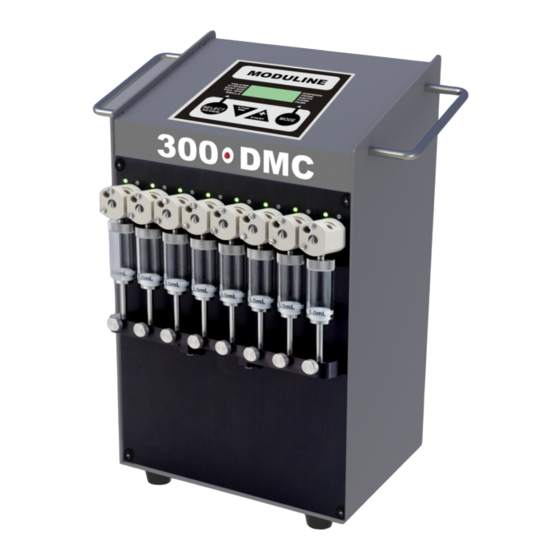
DMC-B (Digital Multi-Channel) Liquid Dispenser
Operation Manual
12513 Loma Rica Drive, Grass Valley, CA 95945
Phone: (530) 272-8786 / Fax: (530) 272-1638
/
Email:
info@modulinesystems.com
Web:
www.modulinesystems.com
Moduline Systems/Manuals/Model 300 DMC Digital/Revised 2-11-13
i
Advertisement
Table of Contents

Related Manuals for Moduline systems DMC-B

Summary of Contents for Moduline systems DMC-B
- Page 1 Reliable liquid dispensing at an affordable price DMC-B (Digital Multi-Channel) Liquid Dispenser Operation Manual 12513 Loma Rica Drive, Grass Valley, CA 95945 Phone: (530) 272-8786 / Fax: (530) 272-1638 Email: info@modulinesystems.com Web: www.modulinesystems.com Moduline Systems/Manuals/Model 300 DMC Digital/Revised 2-11-13...
-
Page 2: Table Of Contents
- Syringe Replacement - Valve Replacement DMC-B Specifications Figures # 1 DMC-B Back Panel # 2 DMC-B Display and Controls # 3 Inlet Manifold Installation # 4 Typical Dispenser Conveyor Configuration # 5 Conveyor Off Track Installation # 6 Conveyor Back Panel... -
Page 3: Introduction
INTRODUCTION The DMC-B (Digital Multi-Channel) is a liquid dispenser designed for stand-alone operation or in conjunction with Moduline Systems conveyors or vial filling platforms. It is ideal for pre-production process validation, yet capable of performing well in a low to medium duty production environment. -
Page 4: General System Information
Reliable liquid dispensing at an affordable price GENERAL SYSTEM INFORMATION 1. Power must be off when changing syringes or valves to prevent possible injury in the advent of accidental triggering. 2. When positioning the inlet and outlet fluid lines avoid any sharp bending that may cause kinking. -
Page 5: Dispenser Operation
Reliable liquid dispensing at an affordable price 6. Connect inlet tubing to inlet port located in the face of the rotary shear valves. The default inlet tubing has an ID of 0.066” and is indicated by yellow strain relief. 7. Connect outlet tubing to the ports located on top of the of rotary shear valves. Connect other end to the dispense head, if not already done. -
Page 6: Conveyor Setup
CONVEYOR SETUP Refer to Figures 1, 4 - 7 for visual assistance with the following instructions. 1. Set the conveyor and DMC-B on a suitable table or workbench arranged with the DMC-B behind the conveyor. See Figure 4. 2. Join the off track to the handle grip on the left hand side of the conveyor using the screws provided in the handle. -
Page 7: Using The System
Reliable liquid dispensing at an affordable price Dispensing Recommendations 1. Following a period of nonuse dispense several times into a trial plate to avoid evaporative losses from the outlet needles. 2. If the inlet Cannula is removed from the reservoir it is recommended the system be re-primed to prevent a possible dispensing error caused by an introduced air bubble. -
Page 8: Maintenance
Reliable liquid dispensing at an affordable price CLEANING AND MAINTENANCE To obtain optimum performance and maximum life from the Moduline Systems’ DMC-B Dispenser it is important that the recommended cleaning and maintenance instructions are followed. Routine Maintenance 1. Daily Maintenance a. - Page 9 Replace the tubing if necessary. Frequency of replacement will be dependent on duty cycle, reagents and maintenance. RECOMMENDED DMC-B SYRINGE SERVICE PROCEDURE Reagent to use: Isopropyl alcohol (IPA) 70% Weekly Empty the reagent being used. Put inlet Cannula(s) into IPA. Prime for 10 cycles.
-
Page 10: Syringe Replacement
Reliable liquid dispensing at an affordable price SYRINGE REPLACEMENT To replace the syringe, empty all fluid from the syringe, remove inlet lines from fluid reservoir, then follow the steps below: 1. To replace the syringe, turn the power on and initiate the prime cycle. When the syringe activator arm is at the bottom of its stroke, turn the power off. -
Page 11: Valve Replacement
Reliable liquid dispensing at an affordable price VALVE REPLACEMENT 1. Remove syringe as described in steps 1 - 3 on page 8. 2. Disconnect the tubing from the valve. 3. Remove the two valve screws used to secure the valve to the panel. 4. -
Page 12: Dmc-B Specifications
Fill speed for standard 96 well micro-plate – w/5 mL syringe & Moduline dispensing conveyor µL / well Time (sec) Regulatory Compliance: The DMC-B is a general laboratory device not subject to FDA regulatory approval. UL / CE approved components are used wherever possible. -
Page 13: Dmc-B Back Panel
Reliable liquid dispensing at an affordable price REMOTE TRIGGER RECEPTACLE SLAVE DISPENSER COM. CORD COM. CORD RECEPTACLE MASTER POWER SWITCH MODEL TYPE & SERIAL NUMBER POWER CORD RECEPTACLE Figure 1 DMC-B Back Panel... -
Page 14: Dmc-B Display And Controls
Reliable liquid dispensing at an affordable price Figure 2 DMC-B Display and Controls 1. INDICATOR ARROW FOR SELECTED DISPLAY 2. DISPLAYS DISPENSED VOLUME IN uL or mL 3. DISPLAYS SYRINGE SIZE (1.0 mL, 2.50 mL, or 5.0 mL) 4. DISPLAYS DISPENSING SPEED (0-10) 5. -
Page 15: Inlet Manifold Installation
Reliable liquid dispensing at an affordable price Figure 3 Inlet Manifold Installation... -
Page 16: Typical Dispenser Conveyor Configuration
Reliable liquid dispensing at an affordable price 7” 8” Conveyor 23” 34” Figure 4 Typical Dispenser Conveyor Configuration... -
Page 17: Conveyor Off Track Installation
Reliable liquid dispensing at an affordable price Figure 5 Conveyor Off Track Installation Figure 6 Conveyor Back Panel... -
Page 18: Dispense Head Holder Installation
Reliable liquid dispensing at an affordable price DISPENSE HEAD DISPENSE HEAD POSITIONING STOP SCREW MOUNTING SCREWS NEEDLE CENTERING ADJUSTMENT SCREW PLATE POSITION ADJUSTMENT SCREWS REAR TRACK Figure 7 Dispense Head Holder Installation... -
Page 19: Dispense Head Holder Alignment
Reliable liquid dispensing at an affordable price DISPENSE HEAD ALIGNMENT HOLDER ARROW ALIGN END OF BASE WITH ARROW AS SHOWN Figure 8 Dispense Head Holder Alignment...
Need help?
Do you have a question about the DMC-B and is the answer not in the manual?
Questions and answers