Table of Contents
Advertisement
TREK 2 AGP
User's Guide
(C )Copyright 1998
All Rights Reserved.
Manual edition January 1999
Document Number G790
The information in this document is subject to change without prior
notice in order to improve reliability, design and function and does not
represent a commitment on the part of the manufacturer.
In no event will the manufacturer be liable for direct, indirect, special,
incidental, or consequential damages arising out of the use or inability to
use the product or documentation, even if advised of the possibility of
such damages.
This document contains proprietary information protected by copyright.
All rights are reserved. No part of this manual may be reproduced by
any mechanical, electronic, or other means in any form without prior
written permission of the manufacturer.
Trademarks
Phoenix is a trademark of Phoenix Technologies Ltd. CardSoft is a
trademark of SystemSoft Corporation. AutoCAD and Autoshade are
trademarks of Autodesk, Inc. IBM, OS/2, and VGA are trademarks of
International Business Machines Corp. Lotus, 1-2-3, and Symphony are
trademarks of Lotus Development Corp. Windows, Word, MS-DOS, and
Microsoft are trademarks of Microsoft Corp. VESA is a trademark of Video
Electronics Standards Association.
Other product names mentioned herein are used for identification
purposes only and may be trademarks and/or registered trademarks of
their respective companies.
Limitation of Liability
While reasonable efforts have been made to ensure the accuracy of this
manual, the manufacturer and distributor assume no liability resulting
from errors or omissions in this manual, or from the use of the information
contained herein.
MAS001571-02 2/99
(TREK2 AGP)
EHW / MJB
1
Advertisement
Table of Contents
Troubleshooting

Subscribe to Our Youtube Channel
Related Manuals for Micron Electronics TransPort TREK 2 AGP

Summary of Contents for Micron Electronics TransPort TREK 2 AGP
-
Page 1: Limitation Of Liability
TREK 2 AGP (C )Copyright 1998 All Rights Reserved. User’s Guide Manual edition January 1999 Document Number G790 The information in this document is subject to change without prior notice in order to improve reliability, design and function and does not represent a commitment on the part of the manufacturer. -
Page 2: From The Editors
We want to make this guide as useful as possible and welcome your comments. You can send comments to: From the Editors . . . manuals@micronpc.com. This may your first time setting up your computer, in which case, it is hoped that this manual will be an effective resource Whatever reason brought you to reading the user’s guide …... -
Page 3: Table Of Contents
Contents Satety precauations ................... 3 0 Optional port replicator safety ............... 3 1 3. Troubleshooting..........32 Trek 2 User’s Guide Locating a problem ..................3 2 Checking cables and connections ............3 2 Trademarks ....................1 Power-On Self Test ..................3 3 Safety precautions .................. - Page 4 6. Optional fax/modem...........62 11. Using PHDisk Utility........98 Installation ....................6 2 Executing commands ................6 3 Command line options ................9 8 Basic AT commands ................. 6 3 Help screen ....................9 8 Troubleshooting ..................6 7 CREATE option ..................9 8 Service and support ...................
-
Page 5: About This Manual
About this manual Chapter 8: Running BIOS setup We’ll show you how to operate the Setup Utility that’s provided in the computer’s ROM BIOS. This manual contains information to help you get the most from your TREK 2 computer. Whether you are a new or Chapter 9: Software Utilities experienced computer user, you will benefit more from this manual if you are familiar with its organization. -
Page 6: Personal Inventory
208/898-3434 Address: 208/898-3424 Type of equipment Personal computer E-mail address: Model name: TransPort TREK 2 AGP Transport.support@micronpc.com TREK 2 Web site: Federal Communications Commission Radio www.micronpc.com Frequency Interference Statement Note: This equipment has been tested and found to comply with... - Page 7 According to FCC Part 15 Shielded interface cables and a non-shielded AC power cord must be used in order to comply with Responsible Party Name: Micron Electronics, Inc. emission limits. Address: 900 East Karcher Road This equipment is to be used with power supply:...
- Page 8 FCC Class B Statement Optional fax/modem This equipment has been tested and found to comply with the limits for a Class B digital device, pursuant to Part 15 of the FCC Rules. These limits are designed to provide reasonable FCC Compliance protection against harmful interference in a residential This equipment complies with Part 68 of the FCC Rules.
- Page 9 Before installing this equipment, users ensure that it is UL Notice permissible to be connected to the facilities of the local Caution: This internal modem adapter is to be installed in UL telecommunications company. The equipment must also be listed computers only, Always disconnect the modem adapter installed using an acceptable method of connection.
-
Page 10: Getting Started
1. Getting Started Congratulations on your purchase of the TransPort TREK 2. Your TREK 2 features the latest advances in portable computing technology. The TREK 2’s modular design provides maximum expandability — without compromising portability. The high-performance Pentium II CPU and enhanced IDE hard drive provide you with extra processing power for handling complex graphics and running large programs. -
Page 11: Unpacking The Trek 2
If anything is missing or Overheating can destroy computer components, so allow damaged, please contact Micron Electronics immediately. All plenty of room for air to circulate around the case. Do not systems should include the following items: place your TREK 2 in direct sunlight. -
Page 12: System Features
System features Display The LCD assembly comes with either of the following display options: This section provides an overview of the TREK 2’s features. For more detailed information see the Specifications section 12.1" TFT SVGA, 800 x 600 x 64K color resolution in Appendix B. - Page 13 Windows 95 enhanced keyboard USB port The TREK 2 keyboard uses a standard QWERTY layout with Two USB (Universal Serial Bus) connectors are available for the addition of special function keys and an embedded you to connect USB devices. The USB is a personal numeric keypad for number intensive data entry.
-
Page 14: Accessories And Optional Devices
Battery and AC power system Accessories and optional devices The TREK 2 can operate on two power sources; an AC To further enhance the utility of your TREK 2 computer, there adapter, or the rechargeable battery module pack. are several accessories and optional products available. The AC adapter has automatic 100-240V line switching which SO-DIMM 3.3V SDRAM modules will automatically check the power voltage coming out of the... -
Page 15: Opening The Lcd Panel
Opening the LCD panel Front left view At the front of the TREK 2 you will find a retaining latch on the With the LCD screen open, you will see several features display panel which locks the display in closed position when important for operating your TREK 2 computer. -
Page 16: System Status Indicator Panel
Icon Description 2. Power/Suspend/Resume button Indicates AC adapter connected when lit A built-in backlight allows you to comfortably view the screen even when ambient lighting is low. You can also connect an optional external VGA/SVGA color display monitor to the The A icon indicates the primary battery is being external CRT connector on the rear panel of the computer. -
Page 17: Keyboard
5. Keyboard 9. CD-ROM drive Your computer has an 84-key enhanced keyboard which Your TREK 2 comes with a swappable 20X (or faster) 5.25" provides all the functions of a standard 101/102 key keyboard. IDE CD-ROM drive. You’ll be able to reference vast amounts The embedded numeric keypad allows easy number input. - Page 18 13. External headphone jack 18. Cooling fan Connect stereo headphones to this jack to listen to the TREK This fan prevents the TREK 2’s CPU and other internal 2’s audio output. components from becoming overheated. Keep this fan unobstructed to allow proper ventilation to the TREK 2’s 14.
-
Page 19: Right View
The right view 4. Battery Your TREK 2 comes equipped with a factory-installed battery pack module. After the battery runs down, the module can be removed and replaced with a charged battery. Additional battery packs are optional. 5. N/A 6. Optional modem If equipped, there will be an RJ11 connector for modem and fax use. -
Page 20: Rear View
Rear view 4. Parallel port This port allows you to easily connect a parallel printer or plotter using this 25-pin bi-directional female port. 5. Port replicator connector Connect the optional port replicator to the 204-pin port replicator connector. This will further enhance your TREK 2’s portability by making it easy for you to connect and disconnect peripheral devices to your TREK 2. -
Page 21: Bottom View
Bottom view 5. CPU cover This covers the CPU compartment providing easy access to allow for upgrades. Only experienced service technicians should open this cover. 6. Future expansion compartment cover This compartment houses an expansion MPEG-2 card or a 56K fax/modem. Figure 1-6: Bottom view of TREK 2 1. -
Page 22: Operating Environment
Operating environment Connecting to a power source You can use your computer under a wide range of You can use the provided AC adapter to supply your computer environmental conditions. However, to ensure long use and with power from an AC wall outlet. Your computer also comes continued high performance, consider the following factors with a rechargeable battery pack that lets you use the when setting up your computer:... -
Page 23: Turning On Your Computer
Caution! Never turn off or reset your TREK 2 while the hard disk or floppy disk is in use and the FDD and/or HDD status icon is lit; doing so can result in loss or destruction of your data. Always wait at least five seconds after turning off your TREK 2 before turning it back on;... -
Page 24: About The Rom Bios
A few seconds after you turn on your computer, a copyright About the ROM BIOS message appears on your display screen. A memory test Your TREK 2 computer is configured with a customized Basic message will appear next. The test continues until all Input/Output System (BIOS), which is a set of permanently installed memory is tested. - Page 25 Caution! When starting the TREK 2 for the first time, please note you Only use batteries that are provided by Micron Electronics. All have either Windows 95, Windows 98 or Windows NT 4.0 batteries are not the same and therefore should not be treated already installed on your TREK 2.
-
Page 26: Charging The Battery Pack
A word about ergonomics Ergonomics is the study of how people with their different physical characteristics and ways of functioning relate to their working environment (the furnishings and machines they use). The goal of ergonomics is to incorporate comfort, efficiency, and safety into the design of keyboards, computer desks, chairs, and other items in an effort to prevent physical discomfort and health problems in the working environment. -
Page 27: Caring For Your Trek 2
When possible, use a high-quality electrical surge 2. Caring for Your protector when your computer is powered by the AC adapter. It is also a good idea to unplug your computer when it is not in use. TREK 2 Ensure that your hands are clean when you use the touch pad to prevent oil and dirt build-up which can This chapter provides you with information on how to keep impair the touch pad operation. -
Page 28: Safety Instructions
Safety instructions Battery 1. Unplug the TREK 2 from the wall outlet before 1. Do not disassemble the battery. The chemicals cleaning. Do not use liquid cleaners or aerosol inside can damage skin and clothing. cleaners. Use a damp cloth for cleaning. 2. -
Page 29: Batteries And Battery Discharge
Whenever possible, hand-carry the computer in its The learning cycle is listed as follows: carrying case. If you must ship your computer as freight or 1. Turn off the TREK 2 and use the AC adapter to baggage, pack it carefully. Use the original cartons charge the computer’s battery pack to full. -
Page 30: Satety Precauations
Safety precautions Required safety features have been installed in the computer Adjust only those controls that are covered by the to protect you from injury. However, you should use good operating instructions, since improper adjustment of judgment to identify potential safety hazards: other controls may result in damage and may require extensive work by a qualified technician to Read all of these instructions before using your... -
Page 31: Optional Port Replicator Safety
Optional port replicator Do not attempt to service this product yourself, as opening or removing the cabinet may expose you to safety precautions dangerous voltage or other risks. Refer all servicing Read all of these instructions before using your port to service personnel. -
Page 32: Troubleshooting
3: Troubleshooting Software errors can occur at several levels. The ROM BIOS and the operating system can give you a large number of error messages. On top of this, each application software package This chapter describes locating and solving problems that you has its own set of error messages. -
Page 33: Power-On Self Test
Two classifications of malfunctions can be detected during the If the computer is too close to a wall, a cable POST: connection may be loose or the cables may be crimped. Error messages that indicate a failure with either the hardware, the software, or the Basic Input/Output 9. -
Page 34: Contacting Technical Support
Contacting Technical Support If you still have a problem after reading the preceding sections, the next step is to contact Technical Support. Technical Support can determine if the problem is something that requires the computer to be sent in for evaluation. Before you call your Technical Support, however, prepare the following information: Please have the serial number of the computer... -
Page 35: Using The Trek 2
Adjusting the LCD screen display 4. Using the TREK 2 The LCD screen display can be adjusted by the following key combinations. Key combinations Definitions Operating the TREK 2 This chapter provides detailed information on how to use the TREK 2’s sophisticated hardware features. Most of the TREK [Fn] + [F7] Decreases brightness level 2’s hardware features can be described as input and output... -
Page 36: Tour Of The Trek 2 Keyboard
Key descriptions [Esc]: The escape key allows you to cancel any specific command you may have just keyed in. [PrtSc/SysRq]: Pressing this key will cause whatever is on the screen at the time to be printed. In Windows 95,98 or NT the Screen will be copied to the clipboard. Note that in some software programs, this key may be used in conjunction with other keys for other specific functions. - Page 37 Windows 95 keys There are two special Windows 95 keys on the keyboard. A brief description of each key is given below. Figure 4-2: Function keys Function keys The key with the Window 95 logo activates the Start menu button on the bottom left of the screen. Notice the twelve function keys in the top row of the keyboard, appearing in sequence from left to right.
-
Page 38: System Status Window Icons
Figure 4-3: Embedded numeric keypad System status window icons Figure 4-4: System status window AC In: When lit indicates that AC power is connected to the TREK 2 computer. When the numeric keypad is engaged, the NumLock icon will Battery status: This icon only lights when a battery is appear in the System Window. -
Page 39: Touch Pad
Touch pad The TREK 2’s integrated touch pad is compatible with the PS/ 2 mouse. A device driver is not required for working with application software that supports PS/2 mouse operation. Using the touch pad The touch pad is a pressure sensitive pointing device that provides all the features of a two-button mouse. -
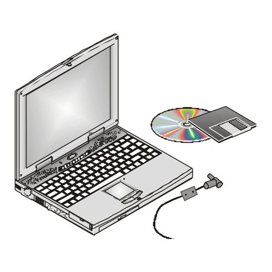
Page 40: Data Storage And Retrieval
Data storage and retrieval There are two ways to drag: Data storage and retrieval are two of the most fundamental tasks you will perform when working with your computer. Move the pointer to the desired location then press down the left button. While still holding down the The TREK 2 is equipped with a 3.5"... -
Page 41: Removing The Floppy Disk Drive
When the FDD is being accessed, a green LED below the Figure 4-6: Removing the floppy disk drive FDD door will illuminate. A read/write head can carry out four basic operations as prescribed by the disk operating system (Windows 95): Read data currently stored on the diskette Write new data to the diskette Erase data from the diskette... -
Page 42: Caring For Diskettes
Caring for diskettes Removable hard disk drive module Under normal conditions a diskette’s rigid plastic case will A hard disk, like a floppy diskette, magnetically stores data protect it from damage. However, data stored on floppy and retains that data when the computer is turned off. Hard diskettes are easily corrupted. - Page 43 Removing and replacing the hard disk drive Disk caching The TREK 2’s hard disk is easily removed and replaced to A disk cache is used to increase hard disk performance. It allow easy upgrades. To remove the hard disk drive: sets aside a portion of the computer’s system memory where frequently used data from the hard disk is temporarily stored.
-
Page 44: Cd-Rom
CD-ROM Features of the CD-ROM module This section covers the information you need for playing both The features of the CD-ROM include: CD-ROM titles and music CDs. Audio play feature allows you to play music CDs The TREK 2 comes with a built-in CD-ROM drive module. The Front panel load/unload button CD-ROM drive employs sophisticated laser and drive 640 MB capacity... -
Page 45: Precautions For Handling Cd-Rom Disks
Removing the CD-ROM drive The CD-ROM drive is removable and swappable with other Installing the CD-ROM drive modules to give you versatility while minimizing weight and To insert the CD-ROM module, slide the module into size. To remove the CD-ROM drive: the drive bay so that it mates with its connector. -
Page 46: Loading A Disc
Loading a disc Reading CDs To play a CD disc, follow the instructions listed below. The CD-ROM drive is designatetd drive D by default. However, it’s treated as a low-priority device by the system. 1. Push the CD-ROM eject button on the CD drive door, For example, if you have other drives installed, they take found on the front of the computer. -
Page 47: Multimedia Sound System
The multimedia sound system IR communication The TREK 2’s built-in audio capabilities allow you to take The TREK 2 is equipped with an Infrared (IR) communication advantage of a wide range of education and entertainment module located on the left side of the TREK 2. If you are multimedia software. -
Page 48: Pmcia Cards And Expansion Sockets
Follow the guidelines listed below when using the infrared Figure 4-9: FIR wireless communication communication module to transmit or receive data. Make sure the infrared communication field in the BIOS Setup program is set to FIR. Refer to Chapter Five for information on the BIOS Setup program. Ensure that the TREK 2’s FIR module is properly lined up with the other device’s infrared communication module. - Page 49 Using PCMCIA cards The PCMCIA (Personal Computer Memory Card International Association) is a widely accepted industry standard that defines the design and operation of PC cards. PC cards that conform to the PCMCIA standard are plug-and-play devices, i.e., they can be inserted into the PCMCIA expansion sockets while the computer is powered on.
- Page 50 Keyboard degree angle. Press gently until you hear a click. 8. Continue this process with additional memory modules in the left slot (Slot 1). Figure 4-12: Keyboard Removal NOTE: The TREK 2 AGP only uses SDRAM and not EDO memory.
-
Page 51: About Power Saving Modes
About power saving modes Removing the battery pack This section contains information on the TREK 2’s power To remove the battery pack from its compartment, please system, including the AC adapter, the battery system, refer to Chapter One, Inserting and Removing the Battery recharging the battery, and tips for conserving battery power. - Page 52 Using battery power Automatic battery pack charging function The battery system will provide approximately 2 to 3 hours of You can automatically charge the battery pack by using the power to the TREK 2. This figure will vary depending on how AC Adapter.
- Page 53 In the Control Panel, double click the Power icon. The This screen indicates how much battery charge remains. following screen will appear If the battery charge drops below a certain voltage level, a beeping sound will prompt you to save your work and turn off the computer, or connect the AC adapter.
- Page 54 When there is only one minute of battery charge remaining, Power management habits the TREK 2 will suspend to the HDD (if a PHDISK HDD While operating the TREK 2 on battery power, it is important partition has been set) and power off. If a PHDISK HDD to develop good power-saving habits to maximize battery life.
- Page 55 Power management modes A suspend example The computer has a number of automatic or adjustable power The time out settings for Hard Disk Off, System Standby, and saving features which you can use to maximize battery life. System Suspend specify the amount of time the system You can control some of these features through the Power must be inactive before the next power management level is menu in the Setup program.
-
Page 56: Power Management Summary
The chain of suspend events Power management summary If the system enters Suspend mode from the above options, it The following table summarizes the TREK 2’s power-saving enters the best power-saving Suspend mode that is supported features: by the system. When the system suspends, the following events take place: Power mode How to enter mode... -
Page 57: The Apm Interface
The APM interface While you are running an APM aware application, APM will detect any system inactivity. If APM detects that either the In addition to the power saving features built into the resident operating system or the application is waiting for input (or is in BIOS System Configuration Utility, your TREK 2 computer some other idle state), APM will reduce the CPU to minimum also supports the Intel-Microsoft Advanced Power... -
Page 58: Connecting Peripheral Devices
To connect a PS/2 compatible mouse to your computer: 1. Plug the PS/2 mini-din connector into the keyboard/ 5. Connecting mouse socket on the left of the computer. 2. The mouse works immediately after being plugged in. Peripheral Devices Additionally it can be used with the internal touch pad. -
Page 59: Serial Devices
After you connect a peripheral device to the serial port, secure the two small screws on the connector. Figure 5-4: Connecting a serial device Figure 5-3: Connecting a printer Serial Devices The rear panel of the TREK 2 computer has a standard RS- 232C serial interface port. -
Page 60: Audio Sources And Output Devices
Audio sources and output devices Figure 5-5: Connecting Audio Devices The built-in audio features of your TREK 2 let you record and play back sound from a variety of sources. These features A udio O u t include: J ack E xt e rnal M icr ophon e J ack PCI stereo sound that supports Microsoft Windows,... -
Page 61: Tv Out
Installing optional devices Located on the bottom of your TREK 2 you will find an expansion card bay. This bay is for future expansion. MPEG2 video decompression module Flatbed 56K fax/modem module Scanner Refer to the following illustration and instructions when installing one of the above expansion cards: 1. -
Page 62: Optional Fax/Modem
6. Optional fax/modem Software Installation Installing Driver for Windows 95/98 This 56K/33.6Kbps FAX/DATA modem connects your If ordered with your TREK 2, Micron has already installed all computer to all popular high-speed modems available today. necessary software for your modem to be recognized by your Your new modem is compatible with systems for simplified operating system. -
Page 63: Executing Commands
To make the command line more readable, spaces may be inserted between commands. If you omit a parameter from a Feature command, which requires one, the default of will be assigned. Example: V.90 (56K model) for highest Internet ATH[ENTER] connection rate Communication Std. - Page 64 DS=n Dial one of the four telephone numbers Set Pulse dial as default (n=0-3) stored in the modem non-volatile Note: Pusle dialing is not supported for memory. UK, Netherlands, Sweden, Norway, Denmark, Finland, Switzerland, Commands are not echoed Germany. Comamnds are echoed Modem sends responses Escape Characters - Switch from Data Modem does not send responses...
- Page 65 &D_ &D0 Modem ignore the DTR signal 6.3 MNP/V.42/V.42bis Commands Disable MNP Class 5 and V.42bis data &D1 Modem return to Command Mode after compression DTR toggle Enable MNP Class 5 and V.42bis data &D2 Modem hang up, returns to the compression only Command Mode after DTR toggle &Q...
- Page 66 Table 7-1 S-Registers Speed Table (unit: bits/s) Section 8 - Result Codes Result Code Numeric Result Code Numeric Connect RING NO CARRIER ERROR CONNECT 1200 EC* NO DIALTONE BUSY NO ANSWER CONNECT 2400 EC* CONNECT 4800 EC* CONNECT 9600 EC* CONNECT 14400 EC* CONNECT 19200 EC* CONNECT 7200 EC*...
-
Page 67: Troubleshooting
Troubleshooting Modem dials but does not connect This section describes some of the common problems you may 1 Make sure the IRQ setting is identical on both the encounter while using your modem. If you can not resolve your modem and the software. Modem and software must difficulty after reading this chapter, contact your dealer or vendor be configured identically. -
Page 68: Service And Support
Modem experiences errors while communicating with a remote modem 1 Make sure the remote system and your modem use the same communication parameters (speed, parity, etc.). 2 Make sure RTS/CTS hardware flow control is enabled and XON/XOFF software flow control is disabled in the communication software. -
Page 69: Optional Port Replicator
7. Optional Port Replicator The port replicator is designed to give your notebook computer the expandability and connectivity of a desktop computer, without sacrificing convenience. In addition, the port replicator has an AC IN connector and a power switch. When the computer is connected to the port replicator, the port replicator controls power to the computer (the computer’s power switch and DC IN connector will be covered). -
Page 70: Features
Two PC card sockets One TV Out Connector One SIR (if equipped) Getting to know the port replicator Before you connect your computer to the port replicator, take a few minutes to become familiar with the port replicator’s features. Front Panel The front panel of the port replicator is shown in figure 7-3 with its corresponding features described after the illustration. -
Page 71: Left Panel
4. Port replicator connector: Connect the notebook computer’s connector into this 204-pin connector. 5. Unit base: This base will serve as a support for the port replicator. 6. Guiding edges: These two edges will serve as an indication that the notebook computer is properly aligned to the port replicator. -
Page 72: Operation
Note: Connecting the notebook computer The PCMCIA sockets of the port replicator do not support ZV. The notebook computer connects to the 204-pin connector on the front of the port replicator. 5. PS/2 Port: This connector accepts an external keyboard Turn off the port replicator with a 6-pin (PS/2-compatible) connector or an external IBM Turn off the notebook computer power... -
Page 73: Cold Dock
4. Locate the two position guides (holes) at the bottom Removing the PC Cards edge of the notebook computer and align it to the guiding bars on the front panel of the port replicator. n Windows 95 or 98, you are able to remove any other PC 5. - Page 74 To remove a PC Card device from the system, first select the device from the list on the Socket Status page and then choose “Stop”. When both the PCMCIA slot of the notebook computer and Windows 95 or 98 shuts down the device and temporarily port replicator are empty, the devices from the list on the disables its drivers.
- Page 75 To do this, you have two options to follow: Procedure 2 By software application Press the “Power” button to enter “Suspend Mode”; press the Click on the “Start” button and select the “Eject PC” option to “Eject” button of the port replicator then push back the “Lever disconnect the two units.
- Page 76 After the internal components are completely disconnected, you are now ready to separate the notebook computer and port replicator manually by following the steps below: Figure 7-8: Disconnecting from the port replicator 1. Push the lever arm backward to completely separate the notebook computer and the port replicator.
-
Page 77: Running Bios Setup
This chapter will guide you through the Setup program by 8: Running BIOS Setup providing clear explanations for all Setup options. A standard configuration has already been set in the Setup Program, so you will very likely have little to worry about for now. However, we recommend that you read this chapter just in Introduction case you need to make any changes in the future. -
Page 78: Launching Submenus
Note: Launching submenus The above items are only a few examples and are by no Note that a right pointer symbol appears to the left of certain means a complete list. fields. This pointer indicates that a submenu can be launched from this field. -
Page 79: Main Menu
Main menu Diskette A When the Setup program is accessed, the main menu Specifies a drive type for diskette drive A. Drive A is the appears. factory-included floppy disk drive. Valid configurations are: Disabled 1.44/1.25 MB 3½” (default value) IDE adapter 0 master System Time: [14:08:58] System Date:... - Page 80 Type Heads The following options are available for this field: This field configures the drive’s number of read/write heads. Refer to your drive’s documentation or look on the drive to Auto (default value) determine the correct value to enter for this field. If the None system has successfully detected the drive automatically, CD-ROM...
- Page 81 LBA (Logical Block Access) mode control Ultra DMA mode When enabled, this option uses 28-bit addressing of the hard When enabled, this option speeds up data transfer to and drive without regard for cylinders, heads, and sectors. Note from the drive. In order to make changes to this field, the that Logical Block Access may decrease the access speed of Type field must be set to User.
-
Page 82: Advanced Menu 8
To configure a hard disk drive or CD-ROM/DVD, move the Extended memory cursor to highlight the IDE Adapter 1 Master field, and This field displays the amount of extended memory detected press the [Enter] key. The IDE Adapter 1 Master submenu by the system during boot-up. - Page 83 Integrated peripherals Selecting Advanced from the menu bar displays the dvanced Pressing the [Enter] key when this field is highlighted calls up menu: the following submenu: Enable ACPI This field enables the Advance Configuration and Power Interface (ACPI) BIOS. ACPI is a power management specification developed by Intel, Toshiba and Microsoft making hardware status information available to the operating system.
- Page 84 Base I/O address ECP mode provides an automatic high burst-bandwidth channel that supports DMA for ECP in both the forward (host When the Serial Port A field is set to Enabled, the “Base I/O to peripheral) and reverse (peripheral to host) direction. Address”...
- Page 85 The security menu User password is: The TREK 2’s advanced system of security allows you to set This field will show Set when you have set a User Password a password to prevent unauthorized access to system as described below. If you have not set the User Password, resources, data, and the BIOS Setup Program.
-
Page 86: Power Menu
Set user password either the Supervisor or User password before allowing access to the Floppy Disk Drive (FDD). When set to This field allows you to set the User password. To set the Supervisor, only the Supervisor password will allow access to User password, follow the same instructions for setting the the FDD. - Page 87 PM control This field allows you to choose the Power Management mode. Standby timeout You can set Power Management to operate at all times or only This field allows you to specify how much time of inactivity when you are using battery power. The options for this field must elapse before the system automatically transits to are: standby mode.
- Page 88 Auto Suspend timeout Battery low suspend This field determines how much system idle time must pass When set to Enabled, suspends to disk when the battery before the system enters Suspend mode. When set to Off , the charge is in a low low state. Possible options include: system cannot enter Suspend mode which is the lowest power state for the TREK 2.
-
Page 89: Boot Menu
The boot menu The exit menu The boot menu allows the user to specify the order in which Once you have made all of your selections from the various the TREK 2 is to check for a device to boot the system. You menus in the Setup program, you should save your changes can also configure the way that the system will boot up. - Page 90 Warning Once this option is selected, the Setup program displays the following message: Configuration has not been saved! Setup Confirmation Setup Confirmation Save before exiting? Save configuration changes and exit now? [Yes] [No] [Yes] [No] Select Yes to save changes and exit the BIOS setup program or press [Esc] to return to the Exit menu.
- Page 91 Select Yes to save any changes to non-volatile RAM. Setup Confirmation Setup Confirmation To exit the BIOS Setup program, open the Exit menu and select one of the exit options. Exit saving changes? Note: [Yes] [No] T o exit BIOS Setup without saving your changes, select Exit Discarding Changes from the Exit menu and press [Enter].
-
Page 92: Software Utilities
9. Software Utilities Please follow all instructions while reloading your system. If you are customizing your notebook and are reloading the operating system, please use the CD-ROM boot diskette that This chapter describes the software utilities that are provided came with your system. Or one can be created by the MCRC with your computer for you. -
Page 93: Vga Utilities
VGA utilities In the upper area you can choose which display device configuration you wish to use: Restart Windows, open Control Panel and double-click the Select this option if you want to view the display output on the display icon. You will notice two in the display properties Notebook’s LCD panel and an external monitor (simultaneous window: television, display device. - Page 94 Select this option if you want to view the Notebook’s display output on a television monitor. Phase Alternating Line. PAL is a European color TV standard that broadcasts an analog signal at 625 lines of resolution 25 interlaced frames per second. The color transmission of a PAL type display is accurate, requiring no hue control on a PAL TV.
- Page 95 Television In the Display Properties window click the Television tab. The Note following screen appears: The S-Video is only supported in this driver version. Color Adjustment You can adjustment your TV display with the available color adjustment of Tint, Saturation and Brightness. Flicker Reduction Use this setting adjsutment to reduce annoying screen flicker.
-
Page 96: 10. Dvd Setup
10. DVD Setup DVD Installation and Setup Note: If you purchased your TREK 2 with DVD, all of this has already been setup and configured for you. You do not need to complete any of these instructions. Just insert a DVD movie, sit back, and enjoy. - Page 97 Insert the DVD-ROM drive into your TREK 2 where the CD- Removing the CD-ROM ROM drive just came out of. Open the LCD assembly and power on your TREK 2. Remove the CD-ROM drive from the bottom of your TREK 2 by sliding the small tab under the front edge of the notebook to the left hand side.
-
Page 98: Using Phdisk Utility
Below is an example of the kind of information that is Using PHDISK Utility displayed when PHDISK is called without a command line option. This example displays Save to Disk PARTITION INFORMATION headers. This header is displayed only when PHDISK.EXE is the utility program you use to prepare your a Save to Disk partition exists. -
Page 99: Reformat Option
REFORMAT Option Syntax User-specified memory size The user may specify a certain amount of memory to be allocated for the Save to Disk function. However, the amount PHDISK/REFORMAT Reformats the Save to of space required to store all system and video memory is PARTITION Disk partition calculated automatically, whenever the CREATE option is... -
Page 100: Phdisk Sign-On
1 0 0 PHDISK Sign-on message Fatal error The following text is displayed when a hard disk error is PHDISK 3.2 - Phoenix NoteBIOS 4.0 (TM) Save to Disk Preparation Utility detected during any Save to Disk operation. (Don’t panic! Copyright (c) Pheonix Technologies Ltd. -
Page 101: Save To Disk Partition
1 0 1 The following text is displayed when the amount of unused First two sectors bad disk space available is less than the amount required to The following text is displayed when the Save to Disk create the Save to Disk partition: partition cannot be used: Error: Not enough free disk space exists to create the suspend to disk partition. -
Page 102: Appendix A: Specifications
1 0 2 Appendix A: Audio ESS Maestro-2 Specifications Sound Blaster Pro Compatible PCI sound/AC 97 ready External audio inputs and amplified output General Dual built-in speakers (1 watt) 3D audio support I/O Ports Pentium II 233, 266, 300, 333, 366 MHz W/MMX/ 15-pin female D-connector video port MMC2, APG2.X (400-pin design) 9-pin male D-connector 16550 UART RS-232 serial... - Page 103 1 0 3 DC-DC Converter Options Supplies 5V, 3.3V CORE VCC and IO VCC, +12V , Spare battery pack: Li-ion MP5V Memory expansion cards: 32MB, 64MB and Contains smart battery charger 128MB /SDRAM Charge modes Mini-docking station with two type II PCMCIA slots Fast: 4 hours charge time with system off or in V.90 fax/modem suspend mode (Li-Ion battery pack)
- Page 104 1 0 4 Altitude Specification Operating: -200~10000ft PC host based controllerless PCI module Non-operating: -200~30000ft Support Win95 Shock Data/Fax Operating: 10G, 11ms Interface: Non-operating: 50G, 11ms 1) DATA:PC/A T parallel bus PNP compatible. Vibration Operating: 10~27Hz, 0.01" 2) LINE:Modular line connector, one RJ11C phone- Non-operating: 5~62Hz, 0.02"...
- Page 105 1 0 5 ERROR CORRECTION: V.42ANDMNP2,3,4. Optional port replicator DATA COMPRESSION: V.42bisANDMNP5. Environment ENHANCED “AT” COMMANDSET . Temperature ASYNCHRONOUS COMMUNICATION * Operating: 5(C~35(C * Non-operating: -20(C~60(C SPECIFICATION BAUD RATE: Humidity (1)DTETOMODEMDATARATE: UP TO 300, 1200, 2400, * Operating: 30%~90% (non-condensing) 4800, 9600, 14400, 19200, 28800, 38400, 57600, 115200, * Non-operating: 5%~95% (non-condensing) 230400BPS...
-
Page 106: Appendix B: Index
1 0 6 Appendix B: Contrast and brightness Cooling fan Cover close switch Index CPU Cover Data storage and retrieval Abbreviations DC-In connector About this manual Disk caching AC Adapter 22, 23 Display Accessories and optional devices Advanced menu 82 Setup 96 APM interface 57 FCC Number 44... - Page 107 1 0 7 Modem (optional) 8, 19 Monitor (see Display) Hard disk drive 42, 43 Multimedia sound system Removing and replacing 43 Heat, cold, humidity, glare Operating environment 22 Index Operating system Infrared communication port 13, 18, 47 Installing peripherals Parallel port 13, 20 PCMCIA...
- Page 108 1 0 8 Safety precautions 28, 30 Security menu 85 Serial port 13, 20, 31, 61 Software utilities Specifications Stereo speakers17 Surge suppressors System features System status indicator 16 Window Technical support Touch pad 17, 39 Buttons 17 Driver 40 Traveling with your computer 28 Troubleshooting 27, 32,67 Turning on the TREK 2...
-
Page 109: Appendix C: Abbreviations
1 0 9 Appendix C: Abbreviations ACPI Enhanced IDE (Integrated Drive Electronics) Advanced Configuration and Power Interface Enhanced Parallel Port Advanced Micro Devices Floppy disk controller Advanced Power Management Fast Infrared ASKIR Amplitude shift keyed infrared port Gigabyte (1GB = 1,073,741,824 bytes or 1,024MB) HP SIR Hewlett-Packard Serial InfraRed AT Attachment (Advanced Technology Attachment) ATAPI... - Page 110 1 1 0 Megabyte (1MB = 1,048,576 bytes or 1,024KB) Read Only Memory MESI Modified Exclusive Shared and Invalid (protocol) Real Time Clock MegaHertz MIDI Serial Infrared Musical Instrument Digital Interface System Management Interrupt Memory Management Unit Standard Parallel Port MultiMedia EXtensions SRAM MPEG...
- Page 111 1 1 1 MAS001571-02 1/99...
Need help?
Do you have a question about the TransPort TREK 2 AGP and is the answer not in the manual?
Questions and answers