Table of Contents

Related Manuals for Koyker 310

Summary of Contents for Koyker 310
- Page 1 OWNERS MANUAL 9/9/2013 MANUAL NO. 657441 LOADER IMPORTANT - KOYKER DEALER BE SURE THIS MANUAL IS GIVEN TO THE PURCHASER FOR FUTURE REFERENCE KOYKER MANUFACTURING CO., P.O. BOX 409 LENNOX, SD 57039 Phone 1-800-456-1107 E-mail koyker@koykermfg.com...
-
Page 3: Table Of Contents
Specifications ............................11 Loader Inspection, Service, and Maintenance ..................12 Hydraulic System Parts Schedule ......................13 Hydraulic System Part Diagram ......................14 “310” Loader Parts Diagram ......................... 15 Part Identification Schedule ........................ 16-17 Hydraulic Cylinder Information ......................18 Hydraulic Information .......................... 19 2 1/2”... -
Page 4: Introduction
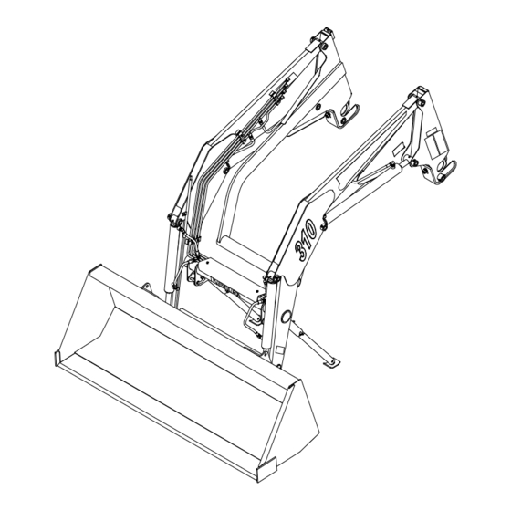
The fast attaching “310” Farm Loader has achieved these goals. With proper care and handling, it will give many years of good service in normal farm operations. -
Page 5: Safety Alert Symbol
SAFETY ALERT SYMBOL The symbol shown below is used to call your attention to instructions concerning your personal safety. Watch for this symbol it points out important safety precautions. It means ATTENTION! Become Alert! Your Personal Safety Is Involved! Read the message that follows and be alert to the possibility of personal injury or death. DANGER: Indicates an imminently hazardous situation that, if not avoided, will result in death or serious injury. -
Page 6: Safety Information
SAFETY Improper use of a loader can cause serious injury or death. The following safety precautions, and those given on the tractor mount installation instructions, should be thoroughly understood before attempting to operate this machine. BEFORE OPERATING: Carefully study and understand this manual, the specific tractor mount instructions, and the attachment(s) manual(s). - Page 7 SAFETY CONTINUED Transport the machine load at the slowest speed possible and with the loader boom at the lowest transport position to avoid tipping or upsetting, which may result in serious injury or death. Be extremely careful when working on inclines or near loose fill, rocks, and holes as they can cause tipping or upsetting which may result in serious injury or death.
- Page 8 1. Move Slowly! 2. Always use care and common sense! 3. Be careful for your own sake and for that of others! 4. Koyker Mfg. Co. includes all reasonable means for accident prevention except a safe and careful operator. FIG. 5-1...
-
Page 9: Safety Decals
SAFETY DECALS Page 6... -
Page 10: Tractor & Safety Pointers
TRACTOR & SAFETY POINTERS The use of good judgment and common sense is necessary by the operator in using this loader. The front and rear wheels should be set for the widest wheel tread to assure best stability. Use extra caution when rear wheel weights and tire ballast are added to a loader-equipped tractor. -
Page 11: Attaching Loader
ATTACHING LOADER 1. Will the loader on the storage stands, drive the tractor into the frame of the loader. Connect the hydraulic lines from the tractor to the loader. 2. Using the tractor hydraulics, activate the loader cylinders to bring the front cross pipe of the loader level with the front yoke receiver of the tractor. -
Page 12: Detaching Loader
Never attempt loader detachment on grades which are not reasonably level. 1. For best results, drive tractor with 310 Loader mounted to reasonably level area. Raise loader up slightly and rotate resting stands to the extra hole in the stand plate and replace stand pin. -
Page 13: Operation
OPERATION WARNING: Never allow anyone to operate the loader until they have carefully reviewed and understood this owners manual. FILLING THE BUCKET: When manure is piled on a slope, it is best to drive tractor up the slope straight into the pile. Operating sideways on a slope has a tendency to tip the loading unit. -
Page 14: Specifications
*Specifications based on ASABE standards S301.3 (Front-End Agricultural Loader Ratings) The above information is based on testing done by Koyker Mfg. Variations in maximum lift height and other specs for different tractors are due to tire sizes, variations in loader mounting locations and hydraulic system efficiency. -
Page 15: Loader Inspection, Service, And Maintenance
LOADER INSPECTION, SERVICE, AND MAINTENANCE Lower the bucket to the ground, shut off tractor engine, and relieve the pressure in the hydraulic system before adjusting, lubricating, or servicing the loader. Inspect all pins and grease fittings before each use and lubricate with heavy duty grease as indicated in this manual. -
Page 16: Hydraulic System Parts Schedule
HYDRAULIC SYSTEM PARTS SCHEDULE PART NUMBER DESCRIPTION QUANTITY 1 ...... 672415 ....2 1/2” Bucket Cylinder ............2 2 ...... 672412 ....2 1/2” Lift Cylinder ............2 3 ...... 657488 ....1st Oil Line (Yellow) ............1 4 ...... 657489 ....2nd Oil Line (Green) ............1 5 ...... -
Page 17: Hydraulic System Part Diagram
HYDRAULIC SYSTEM PARTS DIAGRAM Page 14... -
Page 18: 310" Loader Parts Diagram
KOYKER “310” LOADER PARTS DIAGRAM Page 15... -
Page 19: Part Identification Schedule
14L ..........“Koyker” Decal Left ............1 14R ..........“Koyker” Decal Right ............1 14F ....680205 ....“Koyker” Decal Front ............1 15 ..... 641119 ....Lock Pin ................2 16 ..... 640671 ....#3 Hitch Pin Clip ............... 2 17 ..... - Page 20 PARTS IDENTIFICATION CONTINUED Optional Fast Attach Buckets, Adapters & Standard Buckets PART NUMBER DESCRIPTION QUANTITY 41 ..... 640246 ....#6 Hitch Pin ............... 2 42 ..... 640157 ....Lockwasher; 1/2” .............. 2 43 ..... 640127 ....Hexnut; 1/4” ..............2 44 .....
-
Page 21: Hydraulic Cylinder Information
CYLINDERS IMPORTANT: Read these service tips before beginning assembly of cylinder gland or piston. 1. Keep seals clean from the time they are removed from package until they are installed. 2. Clean the groove or bore into which the seal is to be fitted before installing the seal. 3. -
Page 22: Hydraulic Information
HYDRAULIC SYSTEM The hoses from the tractor valves are attached to the oil lines which are on the inside of the loader main frame. Re-check all joints to prevent leakage after loader is mounted and in operation. KEEP SYSTEM CLEAN - USE ONLY CLEAN OIL CAUTION! It is of utmost importance that the hydraulic system of this loader be kept free from dirt and foreign matter. -
Page 23: 1/2" Cylinder Service Kit
2 1/2” CYLINDER SERVICE KITS KIT NO. 662048: Complete kit with all seals needed to service one (1) 2 1/2” Cylinder. Consists of: 1 each 2 1/2” Gland “O” Ring 1 each 2 1/2” Backup Ring 1 each 1 1/2” U-cup Seal 1 each 1 1/2”... -
Page 24: Hydraulic Cylinder Parts Schedule
HYDRAULIC CYLINDER PARTS SCHEDULE 2 1/2” CYLINDER PARTS LIST LIFT CYLINDER (Part No. 672412) Part No. Description Quantity 1 ...... 672413 ....Tube Weldment ............. 1 2 ...... 661017 ....Locknut ................. 1 3 ...... 651458 ....Piston Assembly ............1 4 ...... -
Page 25: Hydraulic Cylinder Part Diagram
HYDRAULIC CYLINDER PARTS DIAGRAM Page 22... -
Page 26: Piston And Gland Diagram
CYLINDER GLAND SERVICE DIAGRAM All gland seals shown with a section Note: To install rod wiper and U-cup seal, fold similar to shape shown below, slip into gland removed to facilitate correct installation. ROD WIPER bore and locate each in its respective groove. Tools are used to fold seals, take care not to damage sealing surfaces. -
Page 27: Dinoil Valve Hookup
DINOIL VALVE HOOKUP NOTE: Valve normally shipped open center. Part No. #673010 W/Joystick For closed center applications item one (655445) is replaced by item two (673097) and item one is installed in item two. For power beyond applications item one (673096) plug, must be removed and item two (673097) power beyond sleeve must be added. -
Page 28: Limited Warranty
C. ITEMS COVERED SEPARATELY. The Koyker warranties do not cover any parts, components or materials that are part of the Product, or used in conjunction with the Product, that are not manufactured by Koyker. Such parts, components and materials will be subject to the warranties provided by the manufacturer, if any. -
Page 29: Torque Specifications
TORQUE SPECIFICATIONS 1. Tightening Bolts & Nuts Check all loader bolts and nuts for tightness every 50 working hours. The movement of the loader over rough terrain may cause bolts to come under pressure and over a long period of time some slight stretching of the bolt may occur.
Need help?
Do you have a question about the 310 and is the answer not in the manual?
Questions and answers