Table of Contents
Advertisement
Quick Links
Advertisement
Table of Contents
Troubleshooting

Subscribe to Our Youtube Channel
Related Manuals for Leadtek WinFast K7N420DA

Summary of Contents for Leadtek WinFast K7N420DA
- Page 1 K7N415DA/420DA Socket A Motherboards User’s Manual...
- Page 2 The information in this document is subject to change without notice. Leadtek reserves the right to make revisions to this publication without obligation to notify any person or entity of any such changes.
-
Page 3: Table Of Contents
Table of Contents 1. Introduction ................1 1.1 Package Content................ 1 1.2 Specifications ................2 2. Quick Setting................. 3 2.1 Jumper Position................3 2.2 Jumper/Connector Listing ............4 2.3 Jumper Settings ................. 5 3. Hardware Setup..............6 3.1 CPU Installation................6 3.2 Memory Installation .............. - Page 4 Installing LAN Driver ............... 36 5.2.3 Installing Audio Driver ............. 39 5.2.4 Installing VGA Driver (For WinFast K7N420DA only)....42 5.3 Installing DirectX 8.1 ..............45 5.4 Installing Acrobat Utility ............45 6. Speed Gear Operation ............46 7. Appendix................48 7.1 BIOS Flash Utility ..............
-
Page 5: Introduction
1. Introduction WinFast K7N415DA/420DA is a compelling Desktop solution as a Socket A/AMD Athlon, Athlon XP, Athlon, and Duron-based ATX motherboard WinFast K7N415DA/420DA, integrating nForce 415D/420D chipset, supports the AMD Athlon processor whose performance is bound to exceed expectation of both consumer and corporate users alike. -
Page 6: Specifications
1 COM/serial port Memory ♦ 1 parallel port supporting ♦ Supports three 184-pin DDR SPP/EPP/ECP modes DIMMs ♦ 1 VGA port (WinFast K7N420DA ♦ Up to 1.5 GB only) ♦ Supports 128 bit memories ♦ A second COM port (WinFast K7N415DA only) On Board IDE ♦... -
Page 7: Quick Setting
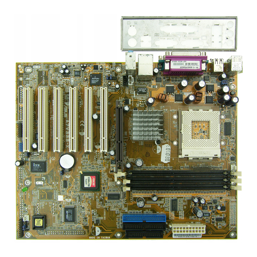
2. Quick Setting Jumper Position FAN1 CPU FAN KYB1 UL 1 NVDIA PWR1 nForce IGP 128 GAME1 IDE2 AGP1 DIMM1 DIMM2 DIMM3 PCI_1 PCI_2 PCI_3 BAT1 ROM1 PCI_4 BATTERY CIR1 FLP1 FLOPPY CD_IN SYS FAN USB1 USB2 FAN3 FAN2 SMART CARD L G G R L G R G 23 24 25... -
Page 8: Jumper/Connector Listing
Jumper/Connector Listing Jumper/Connector Description AGP1 AGP slot BAT1 Battery CN1, CN2, CN3 Line Out, Line In, Mic In ports COM1, COM2 COM1, COM2 connectors DIMM1-3 Memory module connectors FAN1 CPU fan connector FAN2 VGA fan connector FAN3 System fan connector FLP1 Floppy disk connector FP1, FP2... -
Page 9: Jumper Settings
Jumper Settings Clear CMOS Data Jumper Setting Clear CMOS Normal (Default) CPU/FSB Frequency Jumper Frequency Setting 133 MHz 100 MHz (Default) Center/Bass Convert Jumper Setting Normal (Default) Inverse 2nd USB of USB2 Pin Header Selection Jumper Setting USB2 (Default) ACR Slot... -
Page 10: Hardware Setup
3. Hardware Setup Static Precautions Static discharge can damage electronic components. To prevent that, it is important to handle it carefully. The following measures will suffice your equipment from static. Use a grounded wrist strap designed for static discharge. Touch a grounded metal object before you remove the board from the anti-static bag. -
Page 11: Agp Display Adapter Installation
AGP Display Adapter Installation The AGP slot on WinFast K7N415DA/420DA supports only 1.5V 4X AGP device. To install an AGP display adapter, follow these steps: Step 1: Push the clip at the end of AGP slot. Step 2: Position the AGP card over the AGP slot. Do not tilt the card. - Page 12 Hard Disk Connector The on-board Enhanced IDE controller can support up to 4 IDE hard drives or other ATAPI devices, such as CD-ROMs. This controller, as with all Enhanced IDE controllers, consists of both Primary (IDE 1) and Secondary (IDE 2) ports. Each port has an associated connector and cable, which can support up to 2 ATAPI devices each.
- Page 13 Cooling Fans (FAN1, FAN2, FAN3) CPU fan (FAN1), AGP fan (FAN2), and system fan (FAN3) are small 3-pin Header Connectors that provide 12-Volt power for CPU fan, power fan, and system fan. Plug in the fan cable to the connector. Stereo Audio/Video In Connectors (J4, J5, J6) J4 and J5 allows you to receive stereo...
- Page 14 Midi/Joystick, MIC, Line In, Line Out Game Port (Gold) Midi/Joystick: Allow you to connect game joystick or game pad for playing games or connect Midi devices for playing or editing audio. Mic: Allows microphones to be connected for inputting sound. Line In: Allows tape players or other audio sources to be Line Out Line In...
-
Page 15: Bios Setup
4. BIOS Setup The BIOS Setup (also called CMOS Setup) is where many hardware configurations are done and stored. This configuration information will remain in the BIOS until it is changed, or cleared. CMOS refers to the chip in which the BIOS information is stored, even when the power is turned off. -
Page 16: Main Menu
Main Menu Once you enter the AwardBIOS CMOS Setup Utility, the Main Menu appears on the screen. Main Menu presents you the Setup functions included two exit choices. You could use the arrow keys to select among the items and then press Enter to the submenu. - Page 17 Date [mm:dd:yy] The BIOS determines the day of the week from the other date information. It is for information only. Time [hh:mm:ss] The time format is <hour> <minute> <second>. The time is calculated based on the 24-hour military-time clock. For example, 1 p.m. is 13:00:00. IDE Primary Master/ Primary Slave/Secondary Master/Secondary Slave After pressing [Enter], a menu window appears as shown on below: The BIOS supports up to four IDE drives.
- Page 18 Under the AUTO Mode, the BIOS can automatically detect the specifications and optimal operating mode of almost all IDE drives. When you select type Auto for a hard drive, the BIOS detects its specifications during POST, every time the system boots. IT IS RECOMMENDED THAT YOU SELECT THE TYPE AUTO FOR ALL DRIVES.
-
Page 19: Advanced Bios Features
Advanced BIOS Features * The Item Help column contains the description of selected item. Virus Warning [Disabled] The BIOS will halt on the system. Then the warning message appears as follows if there is virus. !PBVA WARNING! Paragon Boot Virus analyzer has detected virus activity on hard disk We recommend you to press: [Enter] Boot from clean disk... - Page 20 First, Second, Third, Fourth Boot Device [HDD-0, Floppy, SCSI, Disabled] Thiese setup fields determine which drive to be searched first, second or third for the disk operating system (i.e. DOS). You can select your priority bootup drives as Floppy drive A, IDE Hard Disk Drive C, D, E, F, or SCSI. Swap Floppy Drive [Disabled] This field is effective only in system with two floppy drives.
-
Page 21: Advanced Chipset Features
Advanced Chipset Features * The Item Help column contains the description of selected item. This section allows you to configure the system based on the specific features of the installed chipset. This chipset manages bus speeds and access to system memory resources, such as DRAM and the external cache. -
Page 22: Integrated Peripherals
Integrated Peripherals This Menu Setup allows you to configure your IDE, USB keyboard, Floppy Drive, Parallel Port, Serial Port, and IR function. * The Item Help column contains the description of selected item. On-Chip IDE Channel0 [Enabled] Selecting Enabled allows you to adjust the functions of Primary PIO and UDMA. On-Chip IDE Channel1 [Enabled] Selecting Enabled allows you to adjust the functions of Secondary PIO and UDMA. - Page 23 Primary Master/Slave UDMA, Secondary Master/Slave UDMA [Auto] Ultra ATA 66/100 implementation is possible only if your IDE hard drive supports it and the operating environment includes a DMA driver (Windows 95 OSR2 or a third-party IDE bus master driver). If your hard drive and your system software both support Ultra ATA 66/100, select Auto to enable BIOS support.
- Page 24 The choices: 3F8/IRQ4, 2F8/IRQ3, 3E8/IRQ4, 2E8/IRQ3, Disabled, and Auto. UART Mode Select Select an infrared port mode. The options are: Normal, IrDA, ASKIR, and SCR. RxD, TxD Active The options are: Hi,Hi, Hi,Lo, Lo,Hi, and Lo,Lo. IR Transmission Delay The options are: Enabled and Disabled. UR2 Duplex Mode This item selects the IR function when the choice of the UART mode is ASKIR.
-
Page 25: Power Management Setup
Power Management Setup * The Item Help column contains the description of selected item. ACPI Function [Enabled] Selecting Enabled allows this function if you use ACPI compliant OS, such as Windows 98 or Windows 2000. ACPI Suspend Type [S1(POS)] Two options are available: S1 (POS) and S3 (STR). POS stands for Power On Suspend. - Page 26 Video Off Method [DPMS Support] This determines the manner in which the monitor is blanked: Blank Screen: This option only writes blanks to the video buffer. V/H SYNC+Blank: This selection will cause the system to turn off the vertical and horizontal synchronization ports and write blanks to the video buffer.
-
Page 27: Pnp/Pci Configurations
PnP/PCI Configurations * The Item Help column contains the description of selected item. The PCI Personal Component Interconnect Bus was developed primarily to address two important issues: (a) How to allow peripheral devices to take the fullest advantage of the power of CPU technology, and (b) Provide a simpler installation process for peripheral devices, such as Network cards, EIDE or SCSI controllers. -
Page 28: Pc Health Status
Auto: If your ISA card and PCI card are all PNP cards. Set this field to "Auto". The BIOS will assign the interrupt resource automatically. IRQ Resources [Press Enter] Pressing Enter will take you to the IRQ Resources setup screen that allows you to assign each IRQ to a device. -
Page 29: X-Bios
X-BIOS * The Item Help column contains the description of selected item. Clock Spread Spectrum [Disabled] When the system clock generator pulses, the extreme values of the pulse generate excess EMI. Enabling pulse spectrum spread modulation changes the extreme values from spikes to flat curves, thus reducing EMI. This benefit may in some cases be outweighed by problems with timing-critical devices, such as a clock-sensitive SCSI device. -
Page 30: Load Basic Defaults
4.11 Load Best Defaults The “Load Best Defaults” function loads the system manufacture default data. This is the default setting from Leadtek. This function will be necessary when the system CMOS data is corrupted or you forget your settings. 4.12 Set Supervisor/User Password Passwords can be set to provide protection for the BIOS configuration options, or to restrict access to the computer itself. -
Page 31: Save & Exit Setup
and press [ENTER]. Enter the current password and press [Enter]. The screen does not display the characters entered. Enter in the new password, then the confirmation. You cannot change the current password unless you know it. To erase a password: If you know the current password, but want to disable password checking, follow the procedure for changing the password. -
Page 32: Driver Installation
5. Driver Installation Under Windows ME/2000/XP The installations of the chipset driver, audio driver, VGA driver and LAN driver under Windows ME/XP/2000 all together take just one click. Follow the steps given below to install all those drivers at once. Step 1: Insert the “WinFast Motherboard &... -
Page 33: Under Windows 98
Under Windows 98 5.2.1 Installing Chipset Driver Step 5: Insert the “WinFast Motherboard & SCSI Software Pack CD” into the CD-ROM drive. Step 6: Your computer will run the Autorun program automatically and the WinFast K7N415DA/420DA setup screen will appear as shown in the figure to the right. - Page 34 Step 9: Another dialog box appears with a list of devices as the figure to the right. Double click on “Other devices”. Then you will see a list of unknown devices. Select “PCI system Management Bus” and then click the “Properties” button. Step 10: Another dialog box appears as shown in the figure to the right.
- Page 35 Step 12: Another dialog box appears with 2 options as shown in figure to the right. Select “Search for a better driver than the one your device is using now…” Then click ‘Next’. Step 13: The dialog box will ask you to help search for the driver.
- Page 36 Step 16: Repeat Step 3 and Step 4 to open the ‘Device Manager’ dialog box. Double click on “System devices”. Then you will see a list of system devices. Select “PCI Standard host CPU bridge” and then click the “Properties” button. Step 17: Another dialog box appears as shown in the figure to the right.
- Page 37 Step 19: Another dialog box appears with 2 options as shown in figure to the right. Select “Search for a better driver than the one your device is using now…” Then click ‘Next’. Step 20: The dialog box will ask you to help search for the driver.
- Page 38 Step 23: Repeat Step 3 and Step 4 to open the ‘Device Manager’ dialog box. Double click on “System devices”. Then you will see a list of system devices. Select “PCI Standard RAM Controller” and then click the “Properties” button. Step 24: Another dialog box appears, click the ‘Driver’...
- Page 39 Step 26: Another dialog box appears with 2 options as shown in figure to the right. Select “Search for a better driver than the one your device is using now…” Then click ‘Next’. Step 27: The dialog box will ask you to help search for the driver.
-
Page 40: Installing Lan Driver
If you get a new floppy disk or CD_ROM from your local dealer which contains a new version of the BIOS binary file, or you obtain the new BIOS binary file directly from our Web Site (www.leadtek.com.tw), please follow the steps below to update the BIOS. -
Page 41: Troubleshooting Procedures
Troubleshooting Procedures Use the following procedures for troubleshooting. If you have followed all of the procedures below and still need assistance, contact your vendor or our Technical Support staff. Before Power On Step 1: Make sure there is no short circuit between the motherboard and case. Step 2: Disconnect all the ribbon/wire cables from the motherboard. -
Page 42: Troubleshooting Flowchart
Troubleshooting Flowchart Power On System Power LED Power Supply OK? Video Display Replace Power Supply System Hold Speaker Beeps Mainboad Good Check BIOS Setting & Add-on Card Check Cable & Jumper Settings 1long 3 short beeps Number of Remove Memory Beeps Video Card 1long beep intervals... -
Page 43: Installing Audio Driver
In the event of not finding the solution for your problem, please contact our technical support staff, or E-mail to <service@leadtek.com.tw>, with the following information: Product name: It will be easier for our staff to answer your question if you know the name of the product. -
Page 44: Limited Warranty
Leadtek are not covered by this Limited Warranty. To be eligible for warranty service, a defective product must be sent to and received by Leadtek within fifteen (15) months of the date of sale and be accompanied with proof of purchase. Leadtek does not warrant that this product will meet your requirements;...
Need help?
Do you have a question about the WinFast K7N420DA and is the answer not in the manual?
Questions and answers