Table of Contents
Advertisement
Quick Links
Advertisement
Chapters
Table of Contents

Related Manuals for Copley Controls Corp. XTL

Summary of Contents for Copley Controls Corp. XTL
- Page 1 Xenus XTL™ User Guide P/N 95-00875-000 Revision 3 June 2008...
- Page 2 Xenus XTL User Guide This page for notes.
-
Page 3: Table Of Contents
TABLE OF CONTENTS About This Manual ....................................5 Introduction ....................................9 1.1: Amplifier ....................................10 1.2: CME 2 ....................................11 1.3: CMO/CML .................................... 11 Operational Theory..................................13 2.1: Amplifier Internal Power................................ 14 2.2: Synchronizing PWM Switching Frequency..........................16 2.3: Commutation Modes ................................16 2.4: Feedback.................................... - Page 4 C.1: Operating Temperature and Cooling Configurations ......................160 C.2: Heatsink Mounting Instructions ............................162 Xenus Filter....................................163 D.1: Overview.................................... 164 D.2: XTL-FA-01 Edge Filter Specifications ..........................165 D.3: Thermal Considerations ..............................165 D.4: XTL-FA-01 Edge Filter Dimensions............................ 166 D.5: XTL-FA-01 Edge Filter Wiring ............................167 D.6: XTL-FA-01 Edge Filter Ordering............................
-
Page 5: About This Manual
BOUT ANUAL Overview and Scope This manual describes the operation and installation of the Xenus XTL amplifier manufactured by Copley Controls Corporation. Related Documentation For important setup and operation information, see the CME 2 User Guide. Users of the CANopen features should also read these Copley Controls documents: •... - Page 6 About this Manual Xenus XTL User Guide Product Warnings Observe all relevant state, regional, and local safety regulations when installing and using this product. For safety and to assure compliance with documented system data, only Copley Controls Corporation should perform repairs to amplifiers.
-
Page 7: Revision History
Xenus XTL User Guide About this Manual Revision History Revision Date DECO# Comments December 2007 16236 Initial release. February 2008 16714 Updated Multi-Mode Port Interface Diagram (p. 66). June 2008 17111 Updated Web page references and made other minor changes. - Page 8 About this Manual Xenus XTL User Guide This page for notes. Copley Controls Corp.
-
Page 9: Introduction
CHAPTER 1: I NTRODUCTION This chapter provides an overview of the Copley Controls Xenus XTL amplifier. Contents include: Title Page 1.1: Amplifier ....................................10 1.2: CME 2 ....................................11 1.3: CMO/CML .................................... 11 Copley Controls Corp. -
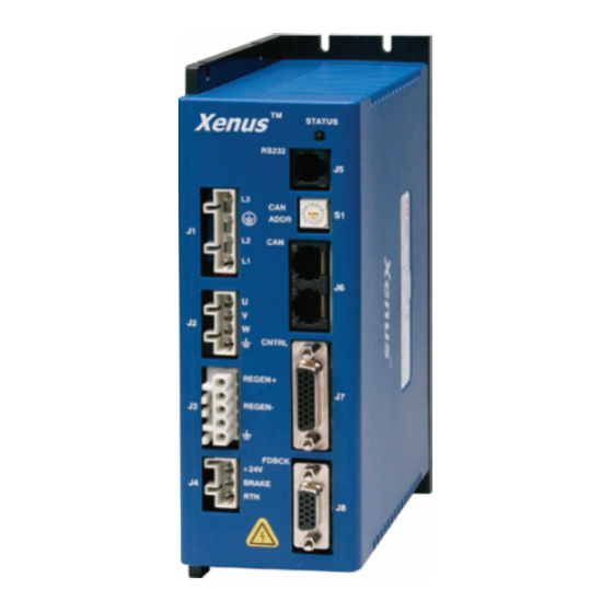
Page 10: Amplifier
Mains input voltage to the amplifier can range from 100 to 240 Vac, single or three-phase, and 47 to 63 Hz. This allows Xenus the ability to work in the widest possible range of industrial settings. Several models are available, with peak current ratings of 18 to 40 amps:... -
Page 11: Cme 2
1.2: CME 2 Amplifier commissioning is fast and simple using Copley Controls CME 2 software. CME 2 communicates with Xenus via an RS-232 link, and all of the operations needed to configure the amplifier are accessible through CME 2. The multi-drop feature allows CME 2 to use a single RS-232 serial connection to one amplifier as a gateway to other amplifiers linked together by CAN bus connections. - Page 12 Introduction Xenus XTL User Guide Copley Controls Corp.
-
Page 13: 2: Operational Theory
CHAPTER 2: O PERATIONAL HEORY This chapter describes the basics of Xenus operation. Contents include: Title Page 2.1: Amplifier Internal Power................................ 14 2.2: Synchronizing PWM Switching Frequency..........................16 2.3: Commutation Modes ................................16 2.4: Feedback....................................16 2.5: Operating Modes .................................. 17 2.6: CANopen Operation ................................ -
Page 14: Amplifier Internal Power
Operational Theory Xenus XTL User Guide 2.1: Amplifier Internal Power Power distribution within Xenus is divided into three sections: +24 Vdc, logic/signal, and high voltage. Each is isolated from the other. 2.1.1: Logic/Signal Power An internal DC/DC converter operates from the +24 Vdc Logic Supply input and creates the required logic/signal operating voltages, the isolated voltages required for the high-voltage control circuits, and a +5 Vdc supply for powering the motor encoder and Hall circuits. - Page 15 Xenus XTL User Guide Operational Theory 2.1.3: Power and Grounding Diagram SHIELD AMPLIFIER CHASSIS REGEN(+) REGEN(-) 1760 PF DC BUSS(+) MOTOR MAINS INVERTER DC BUSS(-) FRAME CASE (SAFETY) GROUND STAGE +24 Vdc CONTROL POWER ISOLATION BARRIER BRAKE SHIELD BRAKE +5 Vdc @...
-
Page 16: Synchronizing Pwm Switching Frequency
2.4: Feedback 2.4.1: Encoder and Resolver Support The Xenus amplifier is offered in three versions to support encoder or resolver feedback. The standard version supports digital quadrature encoders. The -S version supports analog sin/cos encoders. These versions normally require the use of Hall switches for the commutation of brushless motors. -
Page 17: Operating Modes
Xenus XTL User Guide Operational Theory 2.5: Operating Modes 2.5.1: Modes and Control Loops Nesting of Control Loops and Modes Copley Controls amplifiers use up to three nested control loops - current, velocity, and position - to control a motor in three associated operating modes. - Page 18 Operational Theory Xenus XTL User Guide 2.5.2: Current Mode and Current Loop Current Loop Diagram As shown below, the “front end” of the current loop is a limiting stage. The limiting stage accepts a current command, applies limits, and passes a limited current command to the summing junction.
- Page 19 Xenus XTL User Guide Operational Theory Current Loop Gains The current loop uses these gains: Gain Description Cp - Current loop proportional The current error (the difference between the actual and the limited commanded current) is multiplied by this value. The primary effect of this gain is to increase bandwidth (or decrease the step-response time) as the gain is increased.
- Page 20 Operational Theory Xenus XTL User Guide 2.5.3: Velocity Mode and Velocity Loop Velocity Loop Diagram As shown below, the velocity loop limiting stage accepts a velocity command, applies limits, and passes a limited velocity command to the input filter. The filter then passes a velocity command to the summing junction.
- Page 21 Xenus XTL User Guide Operational Theory Diagram: Effects of Limits on Velocity Command The following diagram illustrates the effects of the velocity loop limits. Limited Velocity Commanded Velocity Vel Limit Accel Limit Decel Limit Velocity Loop Gains The velocity loop uses these gains:...
- Page 22 Operational Theory Xenus XTL User Guide 2.5.4: Position Mode and Position Loop Position Loop Diagram The amplifier receives position commands from the digital or analog command inputs, over the CAN interface or serial bus, or from the CVM Control Program. When using digital or analog inputs, the amplifier's internal trajectory generator calculates a trapezoidal motion profile based on trajectory limit parameters.
- Page 23 The output of the position loop is multiplied by this value before being passed to the velocity loop. Position Loop Feedback Xenus supports two position feedback configurations • Single sensor. Position loop feedback comes from the encoder or resolver on the motor.
- Page 24 Analog Command in Position Mode The Xenus Analog Position command operates as a relative motion command. When the amplifier is enabled the voltage on the analog input is read. Then any change in the command voltage will move the axis a relative distance, equal to the change in voltage, from its position when enabled.
- Page 25 Xenus XTL User Guide Operational Theory 2.5.7: PWM Input Two Formats The amplifier can accept a pulse width modulated signal (PWM) signal to provide a current command in current mode and a velocity command in velocity mode. The PWM input can be programmed for two formats: 50% duty cycle (one-wire) and 100% duty cycle (two-wire).
- Page 26 Operational Theory Xenus XTL User Guide 2.5.8: Digital Input Three Formats In position mode, the amplifier can accept position commands via two digital inputs, using one of these signal formats: pulse and direction, count up/count down, and quadrature. In all three formats, the amplifier can be configured to invert the command.
- Page 27 Xenus XTL User Guide Operational Theory Count Up/Count Down Format In the count up/count down format, one input takes each pulse as a positive step command, and another takes each pulse as a negative step command, as shown below. Up Input...
-
Page 28: Canopen Operation
These profiles specify how various types of devices, including motion control devices, can use the CAN network in a highly efficient manner. Xenus supports the relevant CANopen profiles, allowing it to operate in the following modes of operation: profile torque, profile velocity, profile position, interpolated position, and homing. - Page 29 Xenus XTL User Guide Operational Theory 2.6.3: Architecture As shown below, in a CANopen motion control system, control loops are closed on the individual amplifiers, not across the network. A master application coordinates multiple devices, using the network to transmit commands and receive status information. Each device can transmit to the master or any other device on the network.
-
Page 30: Limit Switches
Operational Theory Xenus XTL User Guide 2.7: Limit Switches 2.7.1: Use Digital Inputs to Connect Limit Switches Limit switches help protect the motion system from unintended travel to the mechanical limits. Any of the digital inputs 2-12 can be can be programmed as positive or negative limit switch inputs. -
Page 31: Brake Operation
Xenus XTL User Guide Operational Theory 2.8: Brake Operation 2.8.1: Digital Output Controls Brake Many control systems employ a brake to hold the axis when the amplifier is disabled. Digital output 4 (OUT4) is designed specifically for a brake output. (Other outputs can be used for brake control, but OUT4 is recommended.) Unlike the other outputs, OUT4 is optically isolated from the control... -
Page 32: Status Indicators
Operational Theory Xenus XTL User Guide 2.9: Status Indicators 2.9.1: Amplifier and CAN Interface Status Indicators The amplifier’s status indicator is a bicolor LED labeled STATUS on the amplifier front panel. The CAN interface status indicator is a bicolor LED labeled CAN. Locations are shown below. - Page 33 Xenus XTL User Guide Operational Theory 2.9.3: CAN Interface Status Indicator Operation The amplifier status indicator color/blink codes comply with CAN Indicator Specification 303-3 as described below. Note that green and red codes are often interlaced, each indicating a different set of conditions.
-
Page 34: Protection
2.10.1: Faults Overview Xenus detects and responds to a set of conditions regarded as faults, such as amplifier over temperature and excessive following error. When any fault occurs, with the exception of a following error, the amplifier’s PWM output stage is disabled, the fault type is recorded in the amplifier’s internal error log (which can be viewed with CME 2), and the status LED changes to... - Page 35 Xenus XTL User Guide Operational Theory Fault Descriptions The set of possible faults is described below. For details on limits and ranges, see Fault Levels (p. 49). Fault Description Fault Occurs When… Fault is Corrected When… *Amplifier Over Amplifier's internal temperature exceeds...
-
Page 36: Position And Velocity Errors
Operational Theory Xenus XTL User Guide 2.11: Position and Velocity Errors 2.11.1: Error-Handling Methods In position mode, any difference between the limited position output of the trajectory generator and the actual motor position is a position error. The amplifier’s position loop uses complementary methods for handling position errors: following error fault, following error warning, and a position- tracking window. - Page 37 Xenus XTL User Guide Operational Theory 2.11.5: Following Error Fault Details Position Error Reaches Fault Level As described earlier, position error is the difference between the limited position output of the trajectory generator and the actual position. When position error reaches the programmed Following Error Fault level, the amplifier faults (unless the following error fault is disabled.) As with...
- Page 38 Operational Theory Xenus XTL User Guide 2.11.6: Tracking Window Details Proper Tracking Over Time As described earlier, position error is the difference between the limited position output of the trajectory generator and the actual position. Velocity error is the difference between commanded and actual velocity.
-
Page 39: Communication
Xenus XTL User Guide Operational Theory 2.12: Communication 2.12.1: Communication Interfaces As described below, the amplifier features two communication interfaces, each used for different purposes. Interface Description RS-232 port The amplifier features a three-wire RS-232 port. CME 2 software communicates with the amplifier using a binary protocol over this link for commissioning, adjustments, and diagnostics. -
Page 40: Inputs
Operational Theory Xenus XTL User Guide 2.13: Inputs 2.13.1: Digital Inputs The amplifier has twelve digital inputs (IN1-IN12). Eleven of them appear on the control connector. IN5 appears on the feedback connector, and is intended for the motor over temperature switch (although it can be programmed for any function). -
Page 41: Outputs
Xenus XTL User Guide Operational Theory 2.14: Outputs 2.14.1: Digital Outputs The amplifier has four programmable digital outputs. Three of the outputs (OUT1 - 3) are general- purpose outputs. The fourth (OUT4) is specifically designed as a brake output but can be programmed to perform any of the functions. -
Page 42: Regen Resistor Theory
Operational Theory Xenus XTL User Guide 2.15: Regen Resistor Theory 2.15.1: Regeneration When a load is accelerated electrical energy is converted into mechanical energy. During deceleration the conversion is reversed. This is called regeneration. Some of this regenerated energy is lost to friction in the mechanical system. More of this energy is converted to heat due to R losses in the motor windings, cabling, and drive electronics. -
Page 43: Specifications
CHAPTER 3: S PECIFICATIONS This chapter describes the amplifier specifications. Contents include: Title Page 3.1: Agency Approvals................................. 44 3.2: Power Input ..................................44 3.3: Power Output..................................44 3.4: Control Loops ..................................45 3.5: Regen Circuit Output ................................45 3.6: Digital Command Input ................................. 45 3.7: Analog Command Input ................................ -
Page 44: Agency Approvals
Specifications Xenus XTL User Guide 3.1: Agency Approvals • CE Compliance*: EN 55011 Compatibility EN 61000-6-1 Immunity EN 61010-1 Safety • UL 508C Compliant • RoHS Compliant *CE Declaration of Conformity available at http://www.copleycontrols.com/Motion/Downloads/xenusData.html 3.2: Power Input Model XTL-230-18 (-R, -S) -
Page 45: Control Loops
Xenus XTL User Guide Specifications 3.4: Control Loops Type Current Velocity 100% digital. Position Sampling rate (time) Current 15 kHz (67 Ps) Velocity 3 kHz (333 Ps) Position 3 kHz (333 Ps) Current Loop Small Signal > 2 kHz (Tuning and load impedance dependent) -
Page 46: Analog Command Input
Specifications Xenus XTL User Guide 3.7: Analog Command Input Channels Type Differential, non-isolated Measurement Range ±10 Vdc Maximum Voltage Differential ±10 Vdc Input to Ground ±10 Vdc Input Impedance 66 k Resolution 12 Bit Bandwidth 7 kHz Scan Time 67 µSec... -
Page 47: Brake Output
Xenus XTL User Guide Specifications 3.10: Brake Output Channels Type Current-sinking MOSFET, optically isolated from control/logic ground. Referenced to +24 Vdc logic supply. Internal fly back diode to +24 Vdc. Maximum Sink Current Low Level Output Resistance <0.2 Function Primary function is brake control. -
Page 48: Hall Switch Inputs
Specifications Xenus XTL User Guide 3.14: Hall Switch Inputs Channels Type 74HC14 Schmitt trigger w/ RC Filter 10 k pull up resistor to internal +5 Vdc Input Voltage Range 0 Vdc - +28 Vdc Low Level Input Voltage < +1.35 Vdc High Level Input Voltage >... -
Page 49: Serial Interface
Xenus XTL User Guide Specifications 3.17: Serial Interface Channels Type RS-232 Signals Rxd, Txd, Gnd Baud Rate 9,600 to 115,200 (defaults to 9600 on power up or reset) Data Format N, 8, 1 Flow Control None Protocol Binary or ASCII format... -
Page 50: Power Dissipation
Specifications Xenus XTL User Guide 3.21: Power Dissipation Model: XTL-230-18 (-R, -S) XTL-230-36 (-R, -S) XTL-230-40 (-R, -S) Output Power Mains Voltage Maximum 120 Vac 30 W 55 W 92 W Continuous 240 Vac 40 W 75 W 120 W... -
Page 51: Dimensions
Xenus XTL User Guide Specifications 3.24: Dimensions Copley Controls Corp. - Page 52 Specifications Xenus XTL User Guide Copley Controls Corp.
-
Page 53: Wiring
CHAPTER 4: W IRING This chapter describes the wiring of amplifier and motor connections. Contents include: Title Page 4.1: General Wiring Instructions ..............................54 4.2: AC Mains (J1)..................................56 4.3: Motor (J2) ..................................... 57 4.4: Regen Resistor (J3) (Optional) ............................. 59 4.5: Logic Supply / Brake (J4).............................. -
Page 54: General Wiring Instructions
Wiring Xenus XTL User Guide 4.1: General Wiring Instructions 4.1.1: Electrical Codes and Warnings Be sure that all wiring complies with the National Electrical Code (NEC) or its national equivalent, and all prevailing local codes. DANGER: Hazardous voltages. Exercise caution when installing and adjusting. - Page 55 Xenus XTL User Guide Wiring J2 and J3 Grounds The ground terminals at J2-1 and J3-5 also connect to the amplifier chassis. Motor cases can be safety-grounded in one or optionally both of these ways: • Direct grounding of the motor frame (assuming the frame of the machine is grounded). Attach the metal motor case to the metal machine frame or connect the ground wire of the motor to the metal frame of the machine.
-
Page 56: Ac Mains (J1)
36 A and 40 A models: 12 AWG, 600 V Shielded cable required for CE compliance Wire Insertion/Extraction Tool Wago: 231-131 Connector and tool are included in connector kit XTL-CK or XTL-CA Pin Description Signal Function AC power input (hot or L1) -
Page 57: Motor (J2)
18 A models: 14 AWG, 600 V 36 A and 40 A models: 12 AWG, 600 V Shielded cable required for CE compliance Wire Insertion/Extraction Tool Wago: 231-131 Standard connector and tool are included in connector kit XTL-CK or XTL-CA Pin Description Signal Function Ground... - Page 58 Wiring Xenus XTL User Guide Brushless Motor Wiring Diagram Brushless Amplifier Motor J2-4 J2-3 J2-2 Case J2-1 Ground Brush Motor Wiring Diagram Brush Amplifier J2 Motor J2-4 J2-3 J2-2 Case Ground J2-1 Copley Controls Corp.
-
Page 59: Regen Resistor (J3) (Optional)
18 A models: 14 AWG, 600 V 36 A and 40 A models: 12 AWG, 600 V Shielded cable required for CE compliance Wire Insertion/Extraction Tool Wago: 231-131 Standard connector and tool are included in connector kit XTL-CK or XTL-CA Pin Description Signal Function Regen +... -
Page 60: Logic Supply / Brake (J4)
Wire Size 22 - 14 AWG Recommended Wire 18 AWG Wire Insertion/Extraction Tool Wago: 231-131 Standard connector and tool are included in connector kit XTL-CK or XTL-CA Pin Description Signal Function +24 Vdc return Brake Return or low side of motor brake... -
Page 61: Rs-232 Serial Communications (J5)
Xenus XTL User Guide Wiring 4.6: RS-232 Serial Communications (J5) Mating Connector 6-position, modular connector (RJ-11 style). Copley Controls provides a prefabricated cable and modular-to-9-pin sub-D adapter in RS-232 Serial Cable Kit, PN SER-CK. A diagram of the female connector is shown below. -
Page 62: Can Bus (J6)
Xenus XTL User Guide 4.7: CAN Bus (J6) Mating Connector 8-position, modular connector (RJ-45 style). Copley Controls provides the following assemblies: • Prefabricated 10 foot cable, PN XTL-NC-10 • Prefabricated 1 foot cable, PN XTL-NC-01 • Terminator Plug, PN XTL-NT A diagram of the female connector is shown below. -
Page 63: Control (J7)
26 Position, 0.1 x 0.09 High Density D-Sub Male, Solder Style Norcomp 180-026- 24 - 30 AWG Connector 103L001 Back shell Norcomp 979-015- 020R121 Solder style connector included in Connector Kit PN XTL-CK. Pin connections are shown here: J7 pin connections Copley Controls Corp. - Page 64 Wiring Xenus XTL User Guide J7 Pin Description Signal Function Frame Ground Cable shield connection Ref - Input Analog command negative input Ref + Input Analog command positive input Speed Pull-Up/Pull- Down Enable Standard Group 1 Standard Group 1 Standard...
- Page 65 Xenus XTL User Guide Wiring Mode-Dependant Dedicated Inputs These inputs are dedicated to specific functions, depending on operating mode. Mode Selected Command Source Function Digital Input Digital Input Multi-Mode Port Single Ended Differential Current & Velocity 9(+) & 7(-) A & /A...
- Page 66 Wiring Xenus XTL User Guide Digital Outputs Wiring Diagram Amplifier Typical Output Loads + 5 Vdc Typical Relay Circuit Lamp OUT1 Motion J7-16 External Controller OUT2 J7-17 Power OUT3 Supply J7-18 Signal J7-15 Ground * Flyback diode required for inductive loads...
-
Page 67: Motor Feedback (J8)
15 Position, High-Density D-Sub Male Solder Style Norcomp 180-015- 24 - 30 AWG Connector 103L001 Back shell Norcomp 939-009- 020R121 Solder style connector included in Connector Kit PN XTL-CK Pin connections are shown here: J8 pin connections Copley Controls Corp. - Page 68 Wiring Xenus XTL User Guide J8 Pin Description Quad A/B Incremental Encoder Xenus Signal Function Frame Ground Cable shield connection +5 Vdc Encoder and/or Halls +5 Vdc power supply output. Total load current on J7-20, J8-2, and J8-4 not to exceed 400 mA.
- Page 69 Xenus XTL User Guide Wiring J8 Pin Description Analog Sin/Cos Encoder Xenus (-S) Signal Function Frame Ground Cable shield connection +5 Vdc Encoder and/or Halls +5 Vdc power supply output. Total load current on J7-20, J8-2, and J8-4 not to exceed 400 mA.
- Page 70 Wiring Xenus XTL User Guide Hall Switch Wiring Diagram Amplifier + 5 Vdc Typical Circuit 10 K Halls Hall J8-3 10 K Hall J8-6 Hall 3.3 ƒ J8-9 5 Vdc Halls J8-4 @ 400 mA Power J8-2 Frame Gnd J8-1...
- Page 71 Xenus XTL User Guide Wiring Resolver Wiring Diagram Amplifier J8-3 J8-2 Resolver SIN (+) J8-8 SIN (-) J8-7 COS (+) J8-13 COS (-) J8-12 Frame Gnd J8-1 Case Ground Motor Over Temperature Wiring Diagram Amplifier + 5 Vdc 4.99 K...
- Page 72 Wiring Xenus XTL User Guide Copley Controls Corp.
-
Page 73: 5: Quick Setup With Cme 2
CHAPTER 5: Q CME 2 UICK ETUP WITH This chapter describes the general procedure for configuring and tuning an amplifier with a motor. (To copy setup data from an existing Copley Controls axis file (.ccx), skip to Quick Copy Setup Procedure (p. 135). -
Page 74: Warnings
Quick Setup with CME 2 Xenus XTL User Guide 5.12.1: Objective ................................126 5.12.2: Steps ................................... 126 5.1: Warnings DANGER: Hazardous voltages. Exercise caution when installing and adjusting. Failure to heed this warning can cause equipment damage, injury, or death. -
Page 75: Cme 2 Installation And Serial Port Setup
Xenus XTL User Guide Quick Setup with CME 2 5.2: CME 2 Installation and Serial Port Setup 5.2.1: Requirements Computer Requirements Minimal hardware requirements: • CPU: Minimum: 400 MHZ* • RAM: Minimum: 128 MB* *Using the minimum requirements will allow CME 2 to run, but performance will be significantly reduced. -
Page 76: 3: Downloading Software From Web (Optional)
Quick Setup with CME 2 Xenus XTL User Guide 5.2.3: Downloading Software from Web (Optional) Choose or create a folder where you will download the software installation file. 5.2.3.1 In an internet browser, navigate to 5.2.3.2 http://www.copleycontrols.com/Motion/Downloads/index.html. Under Software Releases, click on CME 2. -
Page 77: 5: Serial Port Setup
Xenus XTL User Guide Quick Setup with CME 2 5.2.5: Serial Port Setup One or more serial ports on a PC can be used to connect amplifiers. Use the following instructions to add (enable) ports for amplifiers, to choose baud rates for those ports, and to remove (disable) ports for amplifiers. - Page 78 Quick Setup with CME 2 Xenus XTL User Guide Click Next to save the choices and open the Communications Wizard Configure Serial 5.2.5.5 Ports screen. Configure the selected ports. 5.2.5.6 Highlight a port in the Selected Ports list. Choose a Baud Rate for that port.
-
Page 79: Prerequisites
Xenus XTL User Guide Quick Setup with CME 2 5.3: Prerequisites 5.3.1: Hardware and Equipment Verify that +24 Vdc power is OFF and AC power is OFF. 5.3.1.1 Verify wiring and connections. 5.3.1.2 Ensure the following connections are wired according to the guidelines in Wiring (p. -
Page 80: 2: Starting Cme 2 And Choosing An Amplifier
Quick Setup with CME 2 Xenus XTL User Guide 5.3.2: Starting CME 2 and Choosing an Amplifier NOTE: Digital input 1 (IN1) should be configured as a hardware disable. It may then be used to immediately disable the amplifier. To software disable the amplifier at any time while running CME 2, press function key F12. -
Page 81: Basic Setup
Xenus XTL User Guide Quick Setup with CME 2 5.4: Basic Setup 5.4.1: Basic Setup Screen To configure an amplifier for use with a Copley Controls ServoTube motor, see the CME 2 5.4.1.1 User’s Guide. To load a .ccx file that was prepared for the amplifier/motor combination, see Quick Copy 5.4.1.2... - Page 82 Quick Setup with CME 2 Xenus XTL User Guide View or change the Feedback settings described below. Options vary with amplifier model. 5.4.1.6 Setting Description Hall Type Select Hall type: None, Digital, or Analog (Analog is used with Copley Controls ServoTube motors).
- Page 83 Xenus XTL User Guide Quick Setup with CME 2 View or change the Miscellaneous settings described below. Options vary with amplifier 5.4.1.8 model. Setting Description Commutation Select commutation method: Sinusoidal or Trapezoidal. Use back EMF If selected, will use the motor’s measured back EMF to determine for Velocity motor velocity.
-
Page 84: Motor/Feedback Setup
Quick Setup with CME 2 Xenus XTL User Guide 5.5: Motor/Feedback Setup Motor, Feedback, and Brake settings can be loaded from a file or entered manually into the fields. Choose the appropriate method and perform the steps described: • Load Motor/Feedback/Brake Settings from a File (p. 84) •... -
Page 85: 2: Enter Motor/Feedback/Brake Settings Manually
Xenus XTL User Guide Quick Setup with CME 2 5.5.2: Enter Motor/Feedback/Brake Settings Manually Click Motor/Feedback to open the Motor/Feedback screen. 5.5.2.1 A Motor/Feedback screen representing a typical rotary motor is shown below. Parameters vary with amplifier model. Click the Motor tab to view or change Rotary Motor Setup Parameters (p. -
Page 86: 3: Rotary Motor Setup Parameters
Quick Setup with CME 2 Xenus XTL User Guide 5.5.3: Rotary Motor Setup Parameters View or change the settings described below. Options vary with amplifier model. Metric units are shown here. Setting Description Manufacturer Motor manufacturer’s name. Saved for reference in the motor data file. -
Page 87: 4: Linear Motor Setup Parameters
Xenus XTL User Guide Quick Setup with CME 2 5.5.4: Linear Motor Setup Parameters View or change the settings described below. Options vary with amplifier model. Metric units are shown here. Setting Description Manufacturer Motor maker’s name. Saved in the motor data file. Choose from list or enter manually. -
Page 88: 5: Feedback Parameters, Rotary
Quick Setup with CME 2 Xenus XTL User Guide 5.5.5: Feedback Parameters, Rotary As appropriate for each encoder or resolver, enter the options described here. Feedback Type Parameters/Actions Incremental In the Motor Encoder lines or Position Encoder lines field, enter the number of encoder lines (see encoder or motor data sheet). -
Page 89: 6: Feedback Parameters, Linear
Xenus XTL User Guide Quick Setup with CME 2 5.5.6: Feedback Parameters, Linear As appropriate for each encoder installed, enter the options described below. Feedback Type Parameters/Actions Incremental Choose units and then enter the Encoder Resolution (see encoder or motor data sheet). -
Page 90: 7: Feedback Notes
5.5.7: Feedback Notes Encoder and Resolver Support The Xenus XTL is offered in three versions to support quad A/B encoder, analog sin/cos encoder, or resolver feedback. The encoder versions normally require Hall switches for the commutation of brushless motors. The resolver versions support standard, single speed, transmit-type resolvers. -
Page 91: 8: Brake/Stop Parameters
Xenus XTL User Guide Quick Setup with CME 2 5.5.8: Brake/Stop Parameters Enter the following parameters as appropriate. Parameter Description Brake/Stop Delay Time Range of accepted values: 0 to 10,000 mSec. Brake Activation Velocity Range of accepted values: motor-dependent. PWM Delay Brake/Stop Range of accepted values: 0 to 10,000 mSec. -
Page 92: 9: The Calculate Function
Quick Setup with CME 2 Xenus XTL User Guide 5.5.9: The Calculate Function The Calculate function uses the motor and encoder values entered to calculate initial loop gains and limits. These can be modified later to fine-tune the amplifier. Click Calculate to calculate and display the settings. -
Page 93: Amplifier Configuration
Xenus XTL User Guide Quick Setup with CME 2 5.6: Amplifier Configuration 5.6.1: Digital Inputs Click Input/Output to open the Input/Output screen. 5.6.1.1 A typical Input/Output screen is shown below. (Features vary with amplifier model and configuration.) Red: inhibited motion or active input, depending on input function. Grey: motion not inhibited. None: not configured. -
Page 94: 2: Digital Input Functions
PWM output stage will be enabled. Motor Over Temperature: On the XTL amplifier, IN5 is located on the motor feedback connector and is intended to be used for Motor Over Temperature. Other: Other inputs may have predefined functions depending on mode of operation. -
Page 95: 4: Standard Digital Outputs
Xenus XTL User Guide Quick Setup with CME 2 5.6.4: Standard Digital Outputs Click the Digital Outputs tab of the Input/Output screen. A typical Digital Outputs screen is 5.6.4.1 shown below. (Features may vary with amplifier model and configuration.) Hi/Lo state of output... -
Page 96: 5: Custom Digital Output Settings: Custom Event
Quick Setup with CME 2 Xenus XTL User Guide 5.6.5: Custom Digital Output Settings: Custom Event Any of the amplifier’s digital outputs can be programmed to respond to a combination of events including faults, warnings, and status indications. The output goes active when one or more of the selected events take place. - Page 97 Xenus XTL User Guide Quick Setup with CME 2 …Continued: Custom Events: Status Status Description Amplifier Disabled by Amplifier enable input(s) is not active. Hardware Amplifier Disabled by Amplifier is disabled by a software command. Software Attempting to Stop The amplifier, while in velocity or position mode, has been disabled.
-
Page 98: 6: Custom Digital Output Settings: Custom Trajectory Status
Quick Setup with CME 2 Xenus XTL User Guide 5.6.6: Custom Digital Output Settings: Custom Trajectory Status Any of the amplifier’s digital outputs can be programmed to respond to a combination of amplifier trajectory status conditions. The output goes active when one or more of the conditions is met. -
Page 99: 7: Custom Digital Output Settings: Position Triggered Output
Xenus XTL User Guide Quick Setup with CME 2 5.6.7: Custom Digital Output Settings: Position Triggered Output Any of the amplifier’s digital outputs can be programmed to respond in certain ways to the position of the controlled axis. The output goes active when the axis position meets the specified criteria. -
Page 100: 9: Non-Latched And Latched Custom Outputs
Quick Setup with CME 2 Xenus XTL User Guide 5.6.9: Non-Latched and Latched Custom Outputs Like an amplifier fault, a custom-configured output can be non-latched or latched. If a non-latched, custom-configured digital output goes active, it goes inactive as soon as the last of the selected events is cleared. -
Page 101: 10: Fault Latching
Xenus XTL User Guide Quick Setup with CME 2 5.6.10: Fault Latching Click Configure Faults to open the Fault Configuration screen. 5.6.10.1 To make a fault condition latching, click to put a check mark next to the fault description. 5.6.10.2 Risk of unexpected motion with non-latched faults. -
Page 102: 11: Regen Resistor
Quick Setup with CME 2 Xenus XTL User Guide 5.6.11: Regen Resistor For more information on the external regen resistor, see Regen Resistor Theory (p. 42), and Regen Resistor Sizing and Configuration (p. 145). Click Configure Regen to open the Regen Resistor screen. -
Page 103: Command Input
Xenus XTL User Guide Quick Setup with CME 2 5.7: Command Input Choose the appropriate step for the input format. Input Format Step Analog Analog Input (p. 104) PWM Input (p. 106) Digital Position Digital Position Input (p. 107) CAN Interface (p. 109) ASCII Connecting for Serial Control (p. -
Page 104: 1: Analog Input
Quick Setup with CME 2 Xenus XTL User Guide 5.7.1: Analog Input For more information, see Analog Command Input (p. 23). Click Analog Command to open the mode-specific Analog Command screen. 5.7.1.1 Current mode: Velocity mode: Position mode: Set the input Configuration options described below. - Page 105 Xenus XTL User Guide Quick Setup with CME 2 In position mode, set the Trajectory Limits described below: 5.7.1.4 Option Description Max Velocity Maximum trajectory velocity. Max value may depend upon the back EMF and the Max feedback count. Min:0. Default: 0.25 x motor velocity limit.
-
Page 106: 2: Pwm Input
Quick Setup with CME 2 Xenus XTL User Guide 5.7.2: PWM Input For more information, see PWM Input (p. 25). Click PWM Command to open the PWM Command screen. 5.7.2.1 Set the input options described below. 5.7.2.2 Option Description Scaling Current mode: output current at 100% duty cycle. -
Page 107: 3: Digital Position Input
Xenus XTL User Guide Quick Setup with CME 2 5.7.3: Digital Position Input For more information, see Digital Input (p. 26). Click Digital Position Inputs to open the Digital Position Input screen, 5.7.3.1 Configuration tab. Set the options described below: 5.7.3.2... - Page 108 Quick Setup with CME 2 Xenus XTL User Guide In position mode, enter the options described below: 5.7.3.4 Option Description For More Information Maximum trajectory velocity. Max value may Position Mode and Position Loop (p. 22) Velocity depend upon the back EMF and the Max feedback count.
-
Page 109: 4: Can Interface
Xenus XTL User Guide Quick Setup with CME 2 5.7.4: CAN Interface For more information on CAN see CANopen Operation (p. 28). For information on DeviceNet, see the Copley DeviceNet Programmer’s Guide. Verify that the following connections are wired according to the instructions in 5.7.4.1... -
Page 110: Auto Phase
Quick Setup with CME 2 Xenus XTL User Guide 5.8: Auto Phase 5.8.1: Auto Phase Warnings and Notes Warnings Motor Motion Applying AC power to the amplifier may result in motor motion. Be sure that motor motion will not cause injury. -
Page 111: 2: Auto Phase Procedure
Xenus XTL User Guide Quick Setup with CME 2 5.8.2: Auto Phase Procedure NOTE: The following steps use a brushless rotary motor. Screens and sequences vary by motor type. Verify that the Enable Input is not activated. 5.8.2.1 Apply HV or AC power. - Page 112 Quick Setup with CME 2 Xenus XTL User Guide Activate the Enable Input. 5.8.2.5 Click Start to begin the motor wiring setup. 5.8.2.6 The software displays messages: Configuring Initial Settings, Microstepping, Test Complete, Motor Wiring has been configured. During microstepping, a current vector is applied to the motor windings and microstepped through an electrical cycle at a set rate, causing the motor to move.
- Page 113 If the step fails, see Trouble Shoot Halls Wiring Setup (p. 115). For a resolver (-R) version of Xenus, click Next to open the Resolver Phase Angle Setup 5.8.2.16 screen. Click Start to start the resolver phase angle setup.
- Page 114 Quick Setup with CME 2 Xenus XTL User Guide Click Finish to close the screen and save values to flash memory 5.8.2.18 to close the screen without saving changes, click Cancel. If the Auto Phase algorithm does not produce desired results, try adjusting the Auto Phase 5.8.2.19...
-
Page 115: 3: Guidelines For Choosing Auto Phase Current And Increment Rate Values
Xenus XTL User Guide Quick Setup with CME 2 5.8.3: Guidelines for Choosing Auto Phase Current and Increment Rate Values Here are some considerations in choosing Auto Phase Current and Increment Rate values: • If friction is high, then more current may be required to move the load. -
Page 116: Current Loop
Quick Setup with CME 2 Xenus XTL User Guide 5.9: Current Loop Initial current loop proportional gain (Cp) and current loop integral gain (Ci) values were calculated in previous step. For an introductory overview of the control loops, see Operating Modes (p. -
Page 117: 2: Auto Tune The Current Loop
Xenus XTL User Guide Quick Setup with CME 2 5.9.2: Auto Tune the Current Loop (For instructions on manually tuning the current loop, see the CME 2 User Guide.) The current loop auto tune algorithm applies a square-wave command to the current loop and adjusts current loop proportional gain (Cp) and current loop integral gain (Ci) until a desirable waveform is obtained. - Page 118 Quick Setup with CME 2 Xenus XTL User Guide Observe the auto tune process and results. 5.9.2.6 Auto Tune uses a proprietary algorithm to mimic a standard tuning approach that would be used by a trained technician, as described below: Sets Cp and Ci to zero and then adjusts Cp and Ci for optimal values.
- Page 119 Xenus XTL User Guide Quick Setup with CME 2 Choose an action based on Auto Tune results. 5.9.2.7 Optionally choose which set of values to save: High, Medium, Low, or Original. The Medium values, selected by default, are appropriate for most applications.
-
Page 120: Velocity Loop
Quick Setup with CME 2 Xenus XTL User Guide 5.10: Velocity Loop Initial velocity loop proportional gain (Vp) and velocity loop integral gain (Vi) values were calculated in previous step. 5.10.1: Velocity Loop Settings For more information, see Velocity Mode and Velocity Loop (p. -
Page 121: 2: Manually Tune The Velocity Loop
Xenus XTL User Guide Quick Setup with CME 2 5.10.2: Manually Tune the Velocity Loop To tune the velocity loop, apply square-wave excitation to the velocity loop and adjust velocity loop proportional gain (Vp) and velocity loop integral gain (Vi) to obtain a desired waveform. For instance: NOTE: During tuning, observe any warnings that appear to the left of the trace. -
Page 122: Position Loop
Quick Setup with CME 2 Xenus XTL User Guide 5.11: Position Loop Initial position loop proportional gain (Pp), velocity feed forward (Vff), and acceleration feed forward (Aff) values were calculated in a previous step. 5.11.1: Position Loop Settings For more information, see Position Mode and Position Loop (p. -
Page 123: 2: Manually Tune The Position Loop
Xenus XTL User Guide Quick Setup with CME 2 5.11.2: Manually Tune the Position Loop To tune the position loop, minimize following error and oscillation by running profiles and adjusting position proportional gain (Pp), velocity feed forward (Vff), acceleration feed forward (Aff) and other settings. - Page 124 Quick Setup with CME 2 Xenus XTL User Guide Set up a trapezoidal profile by setting the trajectory limits and distance. See table: 5.11.2.2 Trajectory Limits Tab Parameter Description Maximum Velocity Maximum Set values typical of those expected to be used in the application.
-
Page 125: 3: Test S-Curve Profile
Xenus XTL User Guide Quick Setup with CME 2 5.11.3: Test S-Curve Profile NOTE: Skip this step unless the amplifier will perform CANopen S-Curve profile moves. Jerk is the rate of change of acceleration. S-Curve moves reduce jerk to provide a smooth profile. To tune the level of jerk, run an S-Curve profile and adjust velocity, acceleration, deceleration, and jerk levels until the desired profile is obtained. -
Page 126: Completion Steps
Quick Setup with CME 2 Xenus XTL User Guide 5.12: Completion Steps 5.12.1: Objective Save the work and perform additional testing with load and under normal control source. 5.12.2: Steps On the Main screen, click Save to Flash. 5.12.2.1 Remove AC power from connector J1. -
Page 127: 6: Using Cme 2
6.4.4: Control Functions..............................141 6.4.5: Jog Mode................................141 6.5: Manual Phasing.................................. 142 6.5.1: Manual Phase Objectives ............................142 6.5.2: Manual Phase Instructions, Quad A/B Encoder XTL Xenus ................... 142 6.6: Home Function ................................... 144 6.6.1: Overview................................144 6.6.2: Homing Functions Settings ............................ 144... -
Page 128: Cme 2 Overview
Using CME 2 Xenus XTL User Guide 6.1: CME 2 Overview 6.1.1: Main Screen Overview CME 2 features are called out in the diagram below. Screen details vary depending on amplifier model and mode selection. Details follow in the chapter. -
Page 129: 3: Main Menu Overview
Xenus XTL User Guide Using CME 2 6.1.3: Main Menu Overview The CME 2 Main Menu choices are described below. Menu Selection Description For More Information File Save Amplifier Data Saves contents of amplifier’s RAM to a Manage Amplifier and Motor Data (p. - Page 130 Using CME 2 Xenus XTL User Guide …continued: Menu Selection Description Help CME 2 User Guide Opens the CME 2 User Guide. All Documents Opens the Doc folder in the CME 2 installation folder (typically c://Program Files/Copley Motion/CME 2/Doc). This folder contains all of the related documents that were installed with CME 2.
-
Page 131: 4: Functional Diagram
Xenus XTL User Guide Using CME 2 6.1.4: Functional Diagram The functional diagram, shown below, provides button-click access to most of the screens used to configure an amplifier. It also indicates the flow of control from input, across all active control loops, to motor/feedback. -
Page 132: 5: Can Or Devicenet Information And Status Bar
Using CME 2 Xenus XTL User Guide 6.1.5: CAN or DeviceNet Information and Status Bar The Main screen displays the basic CAN or DeviceNet information. The example below shows CAN information: The Address field shows the amplifier’s present CAN or DeviceNet address. This value is updated... -
Page 133: Manage Amplifier And Motor Data
Xenus XTL User Guide Using CME 2 6.2: Manage Amplifier and Motor Data 6.2.1: Memory To maintain amplifier and motor settings, the amplifier uses volatile RAM memory and non-volatile flash memory. Data can also be saved to disk for backup and distribution. -
Page 134: 3: Data Management Tools
Using CME 2 Xenus XTL User Guide 6.2.3: Data Management Tools Amplifier Data Management Tools Operations performed using the amplifier data management tools at the top of the Main screen (shown below) affect amplifier settings, including motor/feedback data. (CVM Control Program data is not saved by these operations.) -
Page 135: 4: Quick Copy Setup Procedure
Xenus XTL User Guide Using CME 2 6.2.4: Quick Copy Setup Procedure Use this procedure to configure an amplifier/motor pair by copying a .ccx file that was prepared for the amplifier/motor combination. Make sure the amplifier is connected to the PC using the J5 RS-232 connector. -
Page 136: Downloading Firmware
Using CME 2 Xenus XTL User Guide 6.3: Downloading Firmware 6.3.1: Acquiring Firmware from Web Site (Optional) In an internet browser, navigate to: 6.3.1.1 http://www.copleycontrols.com/Motion/Downloads/firmware.html Under click on the appropriate firmware name. 6.3.1.2 When prompted, save the file to the Firmware Image folder in the CME 2 installation 6.3.1.3... -
Page 137: 2: Downloading Firmware To Amplifier
Xenus XTL User Guide Using CME 2 6.3.2: Downloading Firmware to Amplifier NOTE: Firmware can only be downloaded to an amplifier via a direct serial port connection between the amplifier and the PC. CME 2 does not support downloading firmware to a node amplifier via a multi-drop gateway amplifier. -
Page 138: Control Panel
Using CME 2 Xenus XTL User Guide 6.4: Control Panel 6.4.1: Control Panel Overview To access the control panel, click the Control Panel icon ( ) on the Main screen. Each of the features labeled below is described in the following sections. - Page 139 Xenus XTL User Guide Using CME 2 …continued: Indicator States/Description The fault indicator goes red when a fault is active. Check the status message box for a description of the most recent fault: Check the Error Log for a full history of faults and warnings.
-
Page 140: 3: Control Panel Monitor Channels
Using CME 2 Xenus XTL User Guide 6.4.3: Control Panel Monitor Channels The Control Panel Monitor channels can display real-time values on up to three separate variables. To set up a monitor display box, click in the list box and select a variable from the list. -
Page 141: 4: Control Functions
Xenus XTL User Guide Using CME 2 6.4.4: Control Functions The Control area of the screen, shown here, provides functions related to overall amplifier control. The screen options are different when the Position Loop Input is CAN. Control the operational state of the amplifier using the buttons described below. -
Page 142: Manual Phasing
The CME 2 Manual Phase tool lets the user phase a brushless motor, monitor signals, check configuration wiring, and control a microstepping current vector. 6.5.2: Manual Phase Instructions, Quad A/B Encoder XTL Xenus Make sure that no load is connected to the motor. - Page 143 Xenus XTL User Guide Using CME 2 Monitor the vector rotation through one electrical cycle for proper Hall transitions. 6.5.2.7 Verify that the red indicator rotates in the same direction as the motor phase angle, and that the transition occurs when the needle is between indicators (±30 degrees, as shown below).
-
Page 144: Home Function
Using CME 2 Xenus XTL User Guide 6.6: Home Function 6.6.1: Overview The CME 2 Home function can be used to set and test homing parameters. 6.6.2: Homing Functions Settings On Main screen, click Home to open the Homing screen. -
Page 145: A: Regen Resistor Sizing And Configuration
APPENDIX A: R EGEN ESISTOR IZING AND ONFIGURATION This chapter describes the formulas used to determine if a regen resistor is required and what the optimal resistor characteristics would be for a given application. For an overview of regeneration and regen resistors, see Regen Resistor Theory (p. -
Page 146: A.1: Sizing A Regen Resistor
Regen Resistor Sizing and Configuration Xenus XTL User Guide A.1: Sizing a Regen Resistor A.1.1: Gather Required Information Calculating the power and resistance of the regen resistor requires information about the amplifier and the rotary or linear motor application. For all applications, gather the following information: A.1.1.1... - Page 147 Xenus XTL User Guide Regen Resistor Sizing and Configuration A.1.3: Calculate Energy Returned for Each Deceleration Use the following formulas to calculate the energy returned during each deceleration: Rotary motor: = ½ J Where: = Energy returned by the deceleration, in joules.
- Page 148 Regen Resistor Sizing and Configuration Xenus XTL User Guide A.1.6: Determine if Energy Returned Exceeds Amplifier Capacity Compare the amount of energy returned to the amplifier in each deceleration with the amplifier's energy absorption capacity. For related amplifier specifications, see Regen Circuit Output (p.
- Page 149 Xenus XTL User Guide Regen Resistor Sizing and Configuration A.1.10: Calculate Continuous Power to be Dissipated Use the following formula to calculate the continuous power that must be dissipated by the regen resistor. Use each deceleration where energy is dissipated by the regen resistor.
-
Page 150: A.2: Configuring A Custom Regen Resistor
Regen Resistor Sizing and Configuration Xenus XTL User Guide A.2: Configuring a Custom Regen Resistor A.2.1: Regen Configuration Objective and Warning Configure the amplifier to operate properly with the custom resistor. Incorrect values may damage amplifier or external regen resistor. - Page 151 Xenus XTL User Guide Regen Resistor Sizing and Configuration Enter a Continuous Power within the range described. Click Next for Step 3. A.2.2.4 Enter a Peak Power within the range described. Click Next for Step 4. A.2.2.5 Click Next for Step 5.
- Page 152 Regen Resistor Sizing and Configuration Xenus XTL User Guide This page for notes. Copley Controls Corp.
-
Page 153: B: I 2 T Time Limit Algorithm
APPENDIX B: I IMIT LGORITHM The current loop I T limit specifies the maximum amount of time that the peak current can be applied to the motor before it must be reduced to the continuous limit or generate a fault. This chapter describes the algorithm used to implement the I T limit. -
Page 154: B.1: I 2 T Algorithm
Regen Resistor Sizing and Configuration Xenus XTL User Guide B.1: I T Algorithm B.1.1: I T Overview The I T current limit algorithm continuously monitors the energy being delivered to the motor using the I T Accumulator Variable. The value stored in the I... - Page 155 Xenus XTL User Guide Regen Resistor Sizing and Configuration B.1.3: I T Current Limit Algorithm – Application Example T Example: Parameters Operation of the I T current limit algorithm is best understood through an example. For this example, a motor with the following characteristics is used: •...
- Page 156 Regen Resistor Sizing and Configuration Xenus XTL User Guide T Example: Plot Diagrams The plots that follow show the response of an amplifier (configured w/ I T setpoint = 108 A S) to a given current command. For this example, DC output currents are shown in order to simplify the waveforms.
- Page 157 Xenus XTL User Guide Regen Resistor Sizing and Configuration the next 2 seconds since the difference between the actual output current and the continuous current limit is zero. At approximately 3.5 seconds, the commanded current falls below the continuous current limit and once again the output current follows the commanded current.
- Page 158 Regen Resistor Sizing and Configuration Xenus XTL User Guide Copley Controls Corp.
-
Page 159: C: Thermal Considerations
APPENDIX C: T HERMAL ONSIDERATIONS This chapter describes operating temperature characteristics, heatsink options, and heatsink mounting instructions. Contents include: C.1: Operating Temperature and Cooling Configurations ......................160 C.1.2: Heatsink and Fan Configurations .......................... 161 C.2: Heatsink Mounting Instructions ............................162 Copley Controls Corp. -
Page 160: C.1: Operating Temperature And Cooling Configurations
Xenus XTL User Guide C.1: Operating Temperature and Cooling Configurations The following charts show the maximum allowable ambient temperature of Xenus amplifiers for a variety of operating conditions and cooling configurations. The cooling options are for Xenus amplifiers with no heatsink, with the low profile heatsink and with the standard heatsink all with and without forced-air cooling. - Page 161 Xenus XTL User Guide Thermal Considerations C.1.2: Heatsink and Fan Configurations No Heatsink No Fan With Fan* 4.25 in Low-Profile Heatsink No Fan With Fan* 4.25 in Standard Heatsink No Fan With Fan* 4.25 in * Select a 4.25-inch square fan that supplies forced air at a minimum rate of 300 linear feet per minute Copley Controls Corp.
-
Page 162: C.2: Heatsink Mounting Instructions
Phase Change Material Dry Film Interface Pad Transparent Carrier (Discard) Xenus Amplifier NOTE: The drawing shows the standard heatsink kit (XTL-HS), but the mounting instructions given are valid for the low profile heatsink kit (XTL-HL) as well. Copley Controls Corp. -
Page 163: Xenus Filter
APPENDIX D: X ENUS ILTER This chapter provides an overview of the Model XTL-FA-01 edge filter. The contents of this chapter include: Title Page D.1: Overview.................................... 164 D.2: XTL-FA-01 Edge Filter Specifications ..........................165 D.3: Thermal Considerations ..............................165 D.4: XTL-FA-01 Edge Filter Dimensions............................ 166 D.5: XTL-FA-01 Edge Filter Wiring ............................ -
Page 164: D.1: Overview
Xenus XTL User Guide D.1: Overview The XTL-FA-01 edge filter can be used to minimize noise on the output of any Xenus amplifier. D.1.1: Differential and Common Mode Filtering Most noise is capacitively coupled from the motor power cable to neighboring cables. To minimize this noise, the XTL-FA-01 edge filter uses both differential edge filtering and common mode filtering. -
Page 165: D.2: Xtl-Fa-01 Edge Filter Specifications
When used with XTL-40 amplifiers running continuous currents greater than 12 Adc, the XTL-FA-01 should be cooled with an external fan. The fan should have a flow rate of at least 110 CFM. The filter has been tested using the Comair Rotron MD24B2 24 Vdc powered fan. -
Page 166: D.4: Xtl-Fa-01 Edge Filter Dimensions
Xenus Filter Xenus XTL User Guide D.4: XTL-FA-01 Edge Filter Dimensions The following diagram shows the mounting dimensions of the XTL-FA-01 Edge Filter. Copley Controls Corp. -
Page 167: D.5: Xtl-Fa-01 Edge Filter Wiring
DANGER Do not ground mains-connected circuits. With the exception of the ground pins on Xenus J1, J2, and J3 and on Filter J1 and J2, all of the other circuits on these connectors are mains-connected and must never be grounded. - Page 168 Xenus Filter Xenus XTL User Guide D.5.2: Connector Locations Edge Filter J1 connects to Xenus J2. Edge Filter J2 connects to the motor. Copley Controls Corp.
- Page 169 Xenus Filter D.5.3: Cable Notes Keep the Edge Filter J1 to Xenus J2 cable as short as possible. A typical length is 7 inches. To reduce noise, twisted shielded cable must be used and the signal cables should not be bundled in the same conduit.
- Page 170 Xenus Filter Xenus XTL User Guide D.5.6: Diagram: Edge Filter Wiring with Brushless Motor Amplifier Filter Brushless J1-5 Motor J2-4 J2-4 J1-4 J2-3 J2-3 J1-3 J2-2 J2-2 J1-2 Case J2-1 J2-1 J1-1 Ground D.5.7: Diagram: Edge Filter Wiring with Brush Motor...
-
Page 171: D.6: Xtl-Fa-01 Edge Filter Ordering
Xenus XTL User Guide Xenus Filter D.6: XTL-FA-01 Edge Filter Ordering Filter Model Description XTL-FA-01 Xenus Edge Filter Connector Kit Model Description Mfr. Model No. Plug, 5 position, 5.0 mm, female Wago 51118042 or 721-105/026-047/RN01-0000 XTL-FK Plug, 4 position, 5.0 mm, female... - Page 172 Xenus Filter Xenus XTL User Guide Copley Controls Corp.
-
Page 173: E: Connecting For Serial Control
APPENDIX E: C ONNECTING FOR ERIAL ONTROL This chapter describes how to connect one or more amplifiers for control via the RS-232 bus on one of the amplifiers. Copley Controls Corp. -
Page 174: E.1: Single-Axis And Multi-Drop
Connecting for Serial Control Xenus XTL User Guide E.1: Single-Axis and Multi-Drop An amplifier’s RS-232 serial bus can be used by CME 2 for amplifier commissioning. The serial bus can also be used by an external control application (HMI, PLC, PC, etc.) for setup and direct serial control of the amplifier. -
Page 175: Ordering Guide And Accessories
APPENDIX F: O RDERING UIDE AND CCESSORIES This chapter lists part numbers for amplifiers and accessories. Contents include: F.1: Amplifier Model Numbers ..............................176 F.2: Accessory Model Numbers..............................177 F.3: Order Example ................................... 178 F.5: Copley Standard Regen Resistor Specifications......................... 179 F.5.1: Specifications ................................ -
Page 176: F.1: Amplifier Model Numbers
Xenus Servoamplifier 20/40 A with factory-fitted, standard heatsink XTL-230-18-R Xenus Servoamplifier 6/18 A with resolver feedback XTL-230-18-R-HL Xenus Servoamplifier 6/18 A with resolver feedback and factory-fitted, low-profile heatsink XTL-230-18-R-HS Xenus Servoamplifier 6/18 A with resolver feedback and factory-fitted, standard heatsink XTL-230-R-36... -
Page 177: F.2: Accessory Model Numbers
Heatsink Kit, Standard Model Description Heatsink, standard XTL-HS Heatsink thermal material Heatsink hardware mounting kit Regen Resistor Assemblies Model Description XTL-RA-03 Regen Resistor Assembly (for use with XTL-230-18) XTL-RA-04 Regen Resistor Assembly (for use with XTL-230-36 and XTL-230-40) Copley Controls Corp. -
Page 178: F.3: Order Example
Plug, 4 position, 5.0 mm, female Wago: 51111277 or 721-105/026-047/RN01-0000 Insertion / Extraction Tool Wago 231-131 F.3: Order Example Order 1 XTL-230-18 amplifier with standard heatsink fitted at the factory, Connector Kit, CME 2 CD, and serial cable kit: Item Description XTL-230-18-HS... -
Page 179: F.5: Copley Standard Regen Resistor Specifications
If higher settings are required, contact Copley Controls customer support. WARNING Failure to heed this warning can cause equipment damage or injury. F.5.2: Dimensions The diagram below shows XTL-RA-03 and XTL-RA-04 mounting dimensions (in mm). Copley Controls Corp. - Page 180 Xenus XTL™ User Guide 95-00875-000 Revision 3 June 2008 2007, 2008 Copley Controls Corporation 20 Dan Road Canton, MA 02021 USA All rights reserved...
Need help?
Do you have a question about the XTL and is the answer not in the manual?
Questions and answers