Toshiba TECRA S1 Series User Manual
Portable personal computer
Hide thumbs
Also See for TECRA S1 Series:
- User manual (280 pages) ,
- Maintenance manual (268 pages) ,
- Resource manual (56 pages)
Table of Contents
Advertisement
Quick Links
Advertisement
Table of Contents

Related Manuals for Toshiba TECRA S1 Series


Summary of Contents for Toshiba TECRA S1 Series
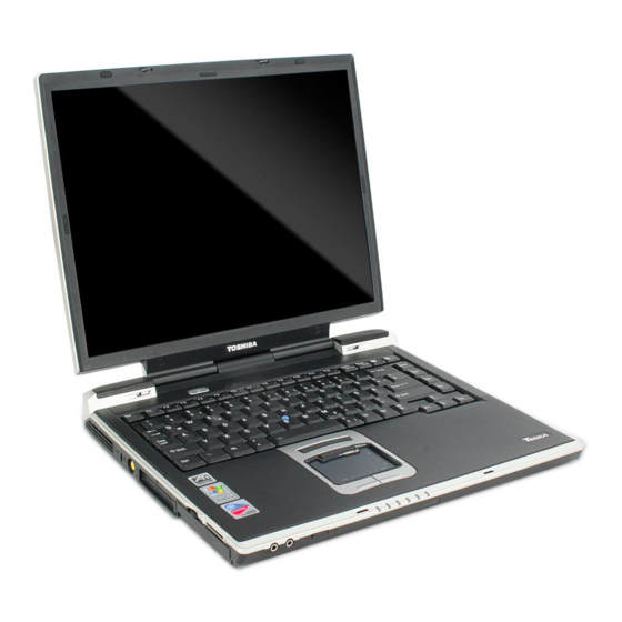
- Page 1 TOSHIBA TECRA S1 Series Portable Personal Computer User’s Manual...
- Page 2 © 2003 by TOSHIBA Corporation. All rights reserved. Under the copyright laws, this manual cannot be reproduced in any form without the prior written permission of TOSHIBA. No patent liability is assumed, with respect to the use of the information contained herein.
-
Page 3: Fcc Information
WARNING: Only peripherals complying with the FCC class B limits may be attached to this equipment. Operation with non-compliant peripher- als or peripherals not recommended by TOSHIBA is likely to result in interference to radio and TV reception. Shielded cables must be used between the external devices and the computer’s external monitor port,... -
Page 4: Fcc Conditions
1. This device may not cause harmful interference. 2. This device must accept any interference received, including interference that may cause undesired operation. Contact Address: TOSHIBA America Information Systems, Inc. 9740 Irvine Boulevard Irvine, California 92618-1697 Telephone: (949) 583-3000... - Page 5 EU Declaration of Conformity TOSHIBA declares, that the product: PT831* conforms to the following Standards: Supplementary Information: “The product complies with the requirements of the Low Voltage Directive 73/23/EEC, the EMC Directive 89/336/EEC and/or the R&TTE Directive 1999/05/EEC.” This product is carrying the CE-Mark in accordance with the related European Directives.
- Page 6 Network Compatibility Statement This product is designed to work with, and is compatible with the following networks. It has been tested to and found to conform with the additional require- ments conditional in EG 201 121. Germany ATAAB AN005,AN006,AN007,AN009,AN010 and DE03,04,05,08,09,12,14,17 Greece ATAAB AN005,AN006 and GR01,02,03,04...
-
Page 7: Type Of Service
Pursuant to FCC CFR 47, Part 68: When you are ready to install or use the modem, call your local telephone company and give them the following information: The telephone number of the line to which you will connect the modem The registration number that is located on the device The FCC registration number of the modem will be found on either the device which is to be installed, or, if already installed, on the bottom of the computer... -
Page 8: If Problems Arise
FCC. In the event repairs are ever needed on your modem, they should be performed by TOSHIBA Corporation or an authorized representative of TOSHIBA Corporation. - Page 9 The customer should be aware that compliance with the above conditions may not prevent degradation of service in some situations. Repairs to certified equipment should be coordinated by a representative designated by the supplier. Any repairs or alterations made by the user to this equipment, or equipment malfunctions, may give the telecommunications company cause to request the user to disconnect the equipment.
- Page 10 Notes for Users in Australia and New Zealand Modem warning notice for Australia Modems connected to the Australian telecoms network must have a valid Austel permit. This modem has been designed to specifically configure to ensure compli- ance with Austel standards when the country/region selection is set to Australia. The use of other country/region setting while the modem is attached to the Australian PSTN would result in you modem being operated in a non-compliant manner.
- Page 11 Some parameters required for compliance with Telecom’s PTC Specifications are dependent on the equipment (PC) associated with this modem. The associated equipment shall be set to operate within the following limits for compliance with Telecom Specifications: There shall be no more than 10 call attempts to the same number within any 30 minute period for any single manual call initiation, and The equipment shall go on-hook for a period of not less than 30 seconds between the end of one attempt and the beginning of the next.
-
Page 12: General Conditions
The transmit level from this device is set at a fixed level and because of this there may be circumstances where the performance is less than optimal. Before reporting such occurrences as faults, please check the line with a standard Telepermitted telephone, and only report a fault if the phone performance is impaired. - Page 13 Optical disk drive standards TOSHIBA TECRA S1 series computer is shipped with one of the following drives preinstalled : CD-ROM, DVD-ROM, CD-R/RW, CD-RW/DVD-ROM, DVD-R/RW or DVD Multi drive. The drive has one of the following labels : CLASS 1 LASER PRODUCT...
-
Page 14: Table Of Contents
Table of Contents Preface Manual contents .................. xx Conventions ..................xxi Abbreviations ..................xxi Icons ....................xxi Keys ....................xxi Key operation ..................xxii Display ....................xxii Messages ..................xxii General Precautions Stress injury ..................xxiv Heat injury ..................xxiv Pressure or impact damage ............ - Page 15 Restarting the computer ..............3-12 Restoring the preinstalled software from the Product Recovery CD-ROM .............. 3-13 Chapter 4 Operating Basics TOSHIBA Dual Pointing Device ............4-1 Using the Touch Pad ................4-2 Using the AccuPoint ................4-2 AccuPoint precautions ................ 4-2 Replacing the cap ................
- Page 16 Changing Slim Select Bay modules ..........4-5 Removing a module ................4-5 Installing a module ................4-6 Using optical media drives ..............4-7 Loading discs ..................4-7 Removing discs ................. 4-10 Writing CDs on CD-RW/DVD-ROM drive .......... 4-11 Before writing or rewiting ..............4-12 When writing or rewiting ..............
- Page 17 Soft keys: Fn key combinations ............5-2 Emulating keys on enhanced keyboard ..........5-2 Hotkeys ....................5-4 Emulating Fn key on external keyboard ..........5-7 Fn Sticky key ..................5-7 Windows special keys ................ 5-8 Keypad overlay ................... 5-8 Turning on the overlays ............... 5-8 Temporarily using normal keyboard (overlay on) ........
- Page 18 Chapter 8 Optional Devices PC cards ....................8-2 Installing a PC card ................8-2 Removing a PC card ................8-3 SD cards ....................8-4 Installing an SD card ................8-4 Removing an SD card ................8-5 Memory expansion ................8-6 Installing memory module ..............
- Page 19 USB ....................9-21 Modem ..................... 9-22 Standby/Hibernation ................9-23 LAN ....................9-24 Wireless LAN ..................9-24 Bluetooth ..................9-25 TOSHIBA support ................9-26 Before you call .................. 9-26 Where to write .................. 9-26 Appendixes Appendix A Specifications ..................A-1 Appendix B Display Controller and Modes ............B-1...
- Page 20 Appendix G Wireless LAN ..................G-1 Appendix H AC Power Cord and Connectors ............H-1 Appendix I Parts Numbers ..................I-1 Glossary Index...
-
Page 21: Preface
Preface Congratulations on your purchase of the TOSHIBA TECRA S1series computer. This powerful, lightweight notebook computer is designed to provide years of reliable, high-performance computing. This manual tells how to set up and begin using your TECRA S1series computer. It also provides detailed information on configuring your computer, basic operations and care, using optional devices and troubleshooting. -
Page 22: Conventions
User's Manual Chapter 6, Power and Power-Up Modes, gives details on the computer’s power resources and battery save modes. Chapter 7, HW Setup and Passwords, explains how to configure the computer using the HW Setup program. It also tells how to set a password. Chapter 8, Optional Devices, describes the optional hardware available. -
Page 23: Key Operation
Conventions Key operation Some operations require you to simultaneously use two or more keys. We identify such operations by the key top symbols separated by a plus sign (+). For example, Ctrl + C means you must hold down Ctrl and at the same time press C. If three keys are used, hold down the first two and at the same time press the third. -
Page 24: General Precautions
User's Manual General Precautions TOSHIBA computers are designed to optimize safety, minimize strain and withstand the rigors of portability. However, certain precautions should be observed to further reduce the risk of personal injury, damage to the computer or impared performance. -
Page 25: Pc Card Overheating
For optimum performance, use your computer product only under recommended conditions. Read additional restrictions in bundled documents. Contact TOSHIBA Service and Support for more information. -
Page 26: Chapter 1 Introduction
Carefully unpack your computer. Save the box and packing materials for future use. Hardware Check to make sure you have all the following items: TECRA S1 series Portable Personal Computer Universal AC adaptor and power cord USB diskette drive (Provided with some models) - Page 27 • Bluetooth driver • Sound Driver for Windows • DVD Video Player • LAN Drivers • Infrared Device Driver • TOSHIBA Dual Pointing Device utility • TOSHIBA Power Saver • TOSHIBA Console • Online manual Documentation: • TECRA S1 Resorce Guide •...
-
Page 28: Features
If any of the items are missing or damaged, contact your dealer immediately. Features The computer uses TOSHIBA’s advanced Large Scale Integration (LSI), Comple- mentary Metal-Oxide Semiconductor (CMOS) technology extensively to provide compact size, minimum weight, low power usage, and high reliability. This computer... - Page 29 User's Manual ® ® 1.5 GHz Mobile Intel Pentium M Processor 1.5 GHz ® Support Enhanced Intel SpeedStep™ technology ® ® 1.6 GHz Mobile Intel Pentium M Processor 1.6 GHz ® Support Enhanced Intel SpeedStep™ technology Memory Slots PC2100 128 or 256 MB or 512MB memory modules can be installed in the two memory slots for a maximum of 1GB system memory.
- Page 30 Features DVD-ROM drive A full-size, DVD-ROM drive module lets you run either (Black) digital versatile or compact disks without using an adaptor. It runs DVD-ROMs at maximum 8 speed and CD-ROMs at maximum 24 speed. This drive supports the same formats as the CD-ROM drive plus the following: •...
- Page 31 See Chapter 5.The Keyboard, for details. TOSHIBA Dual Pointing Device Built-in A Touch Pad and control buttons in the palm rest enable control of the on-screen pointer and scrolling of windows. AccuPoint This pointer control stick, located in the center of the keyboard, provides convenient control of the cursor.
- Page 32 Features PS/2 keyboard/ Connects an external PS/2 keyboard or PS/2 mouse. mouse Docking Special port for connecting an optional Port Replicator. Universal Serial Bus Three Universal Serial Bus (USB) enables chain connec- tion of a number of USB-equipped devices to one port on your computer.
-
Page 33: Slim Select Bay
DVD Multi drive, optional CD-R/RW drive, optional Slim Select Bay HDD adaptor, optional Slim Select Bay 2nd battery pack . The TOSHIBA Mobile Extension enables hot insertion of modules when you are using a plug and play operating system. -
Page 34: Special Features
Special features Special features The following features are either unique to TOSHIBA computers or are advanced features, which make the computer more convenient to use. Hotkeys Key combinations let you quickly modify the system configuration directly from the keyboard without running a system configuration program. -
Page 35: Utilities
TOSHIBA Power Saver To access this power savings management program, open the Control Panel and select the TOSHIBA Power Saver icon. HW Setup This program lets you customize your hardware settings according to the way you work with your computer and the peripherals you use. - Page 36 You can boot ConfigFree from the menu bar as follows. Windows 2000: [Start] - [Programs] - [TOSHIBA ConfigFree] - [ConfigFree] Windows XP: [Start] - [All Programs] - [TOSHIBA ConfigFree] - [ConfigFree] TOSHIBA Dual This utility has the following functions:...
-
Page 37: Options
Main battery pack An additional battery pack 9 cells Type(PA3257*), 6 cells (Black) Type(PA3248*) can be purchased from your TOSHIBA dealer. The battery pack is identical to the one that came with your computer. Use it as a spare or replacement. - Page 38 Options CD-R/RW drive (Black) A full-size, CD-R/RW drive module lets you record CDs as well as run either digital versatile or compact discs without using an adaptor. It runs CDs and CD- Rs at maximum 24 speed and CD-RWs at maximum 14 speed.
-
Page 39: Chapter 2 The Grand Tour
Chapter 2 The Grand Tour This chapter identifies the various components of your computer. Become familiar with each component before you operate the computer. Front with the display closed Figure 2-1 shows the computer’s front with its display panel in the closed position. ISPLAY LATCH IRELESS OMMUNICATION... -
Page 40: Left Side
User's Manual Infrared port This infrared port is compatible with Infrared Data Asso- ciation (IrDA 1.1) standards. It enables cableless 4 Mbps, 1.152 Mbps, 115.2 Kbps, 57.6 Kbps, 38.4 Kbps, 19.2 Kbps or 9.6 Kbps data transfer with IrDA 1.1 compatible external devices. -
Page 41: Right Side
Right side SD card slot This slot lets you transfer data from the device to your computer. SD card Indicator This LED glows green when the computer is accessing the SD card Slot. CAUTION: Keep foreign objects out of the SD card slot. A pin or similar object can damage the computer’s circuitry. -
Page 42: Back Side
User's Manual Slim Select Bay A CD-ROM drive, DVD-ROM drive, CD-R/RW drive, CD- RW/DVD-ROM drive, DVD Multi drive, Slim Select Bay HDD adaptor, secondary battery pack can be installed in the Slim Select Bay. Universal The Universal Serial Bus (USB) port comply with USB2.0 Serial Bus standards,which enables data transfer speeds 40 times faster port... - Page 43 Back side Universal The Universal Serial Bus (USB) port comply with USB 2.0 Serial Bus standards, which enables data transfer speeds 40 times Port faster than the USB 1.1 standards.(The port also support USB 1.1) CAUTION: Keep foreign objects out of the USB connectors. A pin or similar object can damage the computer’s circuitry.
-
Page 44: Underside
User's Manual External monitor This 15-pin port lets you connect an external monitor. port Parallel port This Centronics-compatible, 25-pin parallel port is used to connect a parallel printer or other parallel device. This port supports Extended Capabilities Port (ECP) standard. Serial port Use this 9-pin port to connect external serial devices such as an external modem, a serial mouse or printer. - Page 45 Power and Power-Up Modes, describes how to access the battery pack. Additional battery packs can be pur- chased from your TOSHIBA dealer to extend the computer’s battery operating time. Battery pack Slide this latch to release or the battery pack.
-
Page 46: Front With The Display Open
User's Manual Front with the display open Figure 2-6 shows the front of the computer with the display open. To open the display, slide the display latch on the front of the computer and lift the display up. Position the display at a comfortable viewing angle. ISPLAY SCREEN TEREO PEAKER... - Page 47 Front with the display open Power button Press the power button to turn the computer’s power on and off. AccuPoint A pointer control device located in the center of the keyboard is used to control the on-screen pointer. Refer to the AccuPoint section in Chapter 4, Operating Basics.
-
Page 48: System Indicators
User's Manual System indicators Figure 2-7 shows the system indicators, which light when various computer operations are in progress. DC IN OWER BATTERY IRELESS ELECT COMMUNICATION Figure 2-7 System indicators Power source/system indicators DC IN The DC IN indicator glows green when DC power is supplied from the AC power adaptor. - Page 49 System indicators Slim Select Bay The Slim Select Bay indicator glows green when the computer is accessing a CD-ROM drive, DVD-ROM drive, CD-R/RW drive, CD-RW/DVD-ROM drive, DVD multi drive, Slim Select Bay HDD adaptor or secondary battery pack in the Slim Select Bay. When the secondary battery is charging, the indicator glows orange.
-
Page 50: Usb Diskette Drive
User's Manual APS LOCK Figure 2-9 CapsLock indicator Keyboard indicator Caps Lock This indicator glows green when the alphabet keys are locked in uppercase. USB diskette drive A 3 1/2" diskette drive accommodates 1.44-megabyte or 720-kilobyte diskettes. It connects to the USB port. NDICATOR ISKETTE SLOT JECT BUTTON... -
Page 51: Selim Select Bay Modules
Slim Select Bay modules Disk-In-Use This indicator lights when the diskette is being accessed. Indicator Diskette slot Insert diskette in this slot. Eject button When a diskette is fully seated in the drive, the eject button pops out. To remove a diskette, push in the eject button and the diskette pops out partially for removal. - Page 52 User's Manual INDICATOR JECT HOLE JECT BUTTON Figure 2-11 The optical media device Disc-In-Use This indicator lights when the CD/DVD is being accessed. Indicator Eject button Press the eject button to open the drawer partially. Eject hole Insert a slender object to open the drawer when the power to the computer is off.
-
Page 53: Cd-Rom Drive(Black)
Slim Select Bay modules CD-ROM drive (Black) An optional full-size, maximum 24-speed CD-ROM drive module lets you run either 12 cm (4.72") or 8 cm (3.15") compact discs without using an adaptor. It may be selected as a standard component or as an option. This drive supports the following formats: •... - Page 54 User's Manual This drive supports the following formats: • DVD-ROM • DVD-Video • Photo CD • CD-R • CD-ROM • CD-Rewritable • CD-DA • CD-Text • CD-ROM x A Mode 2 (Form1, Form2) • Enhanced CD (CD-EXTRA) CD-R describes compact discs that can be written only once. The recorded data cannot be erased or changed.
-
Page 55: Dvd Multi Drive(Black)
Slim Select Bay modules DVD Multi drive (Black) The full-size DVD Multi drive module lets you record data to rewritable CD/DVDs as well as run either 12 cm (4.72") or 8 cm (3.15") CD/DVDs without using an adaptor. An ATAPI interface controller is used for CD/DVD-ROM operation. When the computer is accessing a CD/DVD, an indicator on the drive glows and Slim Select Bay indicator glows. -
Page 56: Slim Select Bay Hdd Adaptor(Black)
User's Manual CD-R and DVD-R discs can be written only once. The recorded data cannot be erased or changed. CD-RW discs can be recorded more than once. Use either 1, 2, or 4 multi speed CDRW discs or high-speed 4- to 10-speed discs. The write speed of the high-speed CD-RW discs is maximum 10-speed. -
Page 57: Ac Adaptor
Power and Power-Up Modes for details. Figure 2-14 The AC adaptor CAUTION: Use of the wrong adaptor could damage your computer. TOSHIBA assumes no liability for any damage in such case. The current rating for the computer is 5.0 amperes. 2-19... -
Page 58: Chapter 3 Getting Started
Chapter 3 Getting Started This chapter provides basic information to get you started using your computer. It covers the following topics: Setting up your work space — for your health and safety NOTE: Be sure also to read Instruction Manual for Safety & Comfort. This guide, which is included with the computer, explains product liability. -
Page 59: Setting Up Your Work Space
User's Manual Setting up your work space Establishing a comfortable work site is important for you and your computer. A poor work environment or stressful work habits can result in discomfort or serious injury from repetitive strain to your hands, wrists or other joints. Proper ambient conditions should also be maintained for the computer’s operation. -
Page 60: Seating And Posture
Setting up your work space Set the computer on a flat surface at a comfortable height and distance. The display should be no higher than eye level to avoid eye strain. Place the computer so that it is directly in front of you when you work and make sure you have adequate space to easily operate other devices. -
Page 61: Lighting
User's Manual Lighting Proper lighting can improve legibility of the display and reduce eye strain. Position the computer so that sunlight or bright indoor lighting does not reflect off the screen. Use tinted windows, shades or other screen to eliminate sun glare. -
Page 62: Connecting The Ac Adaptor
Power and Power-Up Modes. CAUTION: Use of the wrong adaptor could damage your computer. TOSHIBA assumes no liability for any damage in such case. The current rating for the computer is 5.0 amperes. 1. Connect the power cord to the AC adaptor. -
Page 63: Opening The Display
User's Manual 3. Plug the power cord into a live wall outlet. The Battery and DC IN indicator on the front of the computer should glow. Opening the display The display panel can be rotated in a wide range of angles for optimal viewing. 1. -
Page 64: Starting Up For The First Time
Turning off the power Figure 3-5 Turning on the power Starting up for the first time When you first turn on the power, the computer’s initial screen is the Microsoft ® ® Windows XP Professional or Windows 2000 Startup Screen Logo. Follow the on-screen directions. -
Page 65: Hibernation Mode
NOTE: For the computer to shut down in hibernation mode, the hiberna- tion feature must be enabled in two places in TOSHIBA Power Saver: the Hibernate window and the Battery Alarm item of the Alarm window. -
Page 66: Starting Hibernation
2. a. In Windows XP, open Performance and Maintenance and open TOSHIBA Power Saver. ® 2000, double-click the TOSHIBA Power Saver icon. b. In Windows 3. Select the Hibernate window, select the Enable Hibernate support check box and click the Apply button. -
Page 67: Standby Mode
User's Manual Data save in hibernation mode When you turn off the power in hibernation mode, the computer takes a moment to save current memory data to the hard disk. During this time, the Built-in HDD indicator will light. After you turn off the computer and memory is saved to the hard disk, turn off the power to any peripheral devices. - Page 68 Windows TOSHIBA Power Saver. ® 2000, double-click the TOSHIBA Power Saver icon. b.In Windows 3. Press the power button. This feature must be enabled. Refer to the System Power Mode item in Power Saver Utility described in the Control Panel.
-
Page 69: Restarting The Computer
2. Hold down the F12 key and turn on the power. When In Touch with Tomorrow TOSHIBA appears, release the F12 key. 3. Use the up or down cursor key to select the CD-ROM drive in the display menu. For details, refer to... -
Page 70: Chapter 4 Operating Basics
Chapter 4 Operating Basics This chapter gives information on basic operations including using the TOSHIBA Dual Pointing Device, USB diskette drive, optical media drives, the microphone, the internal modem, wireless communication, LAN and changing Slim Select Bay modules. It also provides tips on caring for your computer, diskettes and CD/DVDs. -
Page 71: Using The Touch Pad
User's Manual Using the Touch Pad To use the Touch Pad, simply touch and move your finger tip across it in the direction you want the on-screen pointer to go. Two buttons below the Touch Pad are used like the buttons on a mouse pointer. Press the left button to select a menu item or to manipulate text or graphics desig- nated by the pointer. -
Page 72: Replacing The Cap
Using the USB diskette drive Replacing the cap The AccuPoint cap is an expendable item that should be replaced after prolonged use. 1. To remove the AccuPoint cap, firmly grasp the cap and pull it straight up. OINT CAP Figure 4-2 Removing the AccuPoint cap 2. -
Page 73: Connecting 3 1/2" Diskette Drive
User's Manual Connecting 3 1/2" diskette drive To connect the drive, plug the diskette drive connector into a USB port. Refer to Figure 4-3. NOTE: Make sure the connector is right side up and properly aligned with the socket. Do not try to force the connection, doing so can damage the connecting pins. -
Page 74: Changing Slim Select Bay Modules
2. Before removing or inserting a second battery pack, turn off the computer’s power. NOTE: The TOSHIBA Mobile Extension is preinstalled to support hot swapping under Windows. Refer to Chapter 1, Introduction, for informa- tion on using this utility to change modules while the computer’s power is on. -
Page 75: Installing A Module
User's Manual 6. Graps the DVD-ROM drive and Slide it out. CAUTION: The DVD-ROM drive and other Slim Select Bay modules can become hot with use. Be careful when removing the module. ELECT ELECT MODULE LATCH Figure 4-4 Removing the DVD-ROM drive Installing a module Install the Slim Select Bay HDD adaptor as described below. -
Page 76: Using Optical Media Drives
Using optical media drives Using optical media drives The text and illustrations in this section refer primarily to the DVD-ROM drive. However, operation is the same for the CD-RW/DVD-ROM,CD-ROM,DVD Multi and optional CD-R/RW drives. The full-size drive provides high-performance execution of CD/DVD-ROM-based programs. You can run either 12 cm (4.72") or 8 cm (3.15") CD/DVDs without an adaptor. - Page 77 User's Manual b. Pressing the eject button will not open the drawer when the DVD-ROM drive’s power is off. If the power is off, you can open the drawer by inserting a slender object (about 1.5 mm) such as a straightened paper clip into the eject hole just to the right of the eject button.
- Page 78 Using optical media drives 3. Lay the CD/DVD, label side up, in the drawer. Figure 4-9 Inserting a CD/DVD NOTE: When the drawer is fully opened, the edge of the computer will extend slightly over the CD/DVD tray. Therefore, you will need to turn the CD/DVD at an angle when you place it in the tray.
-
Page 79: Removing Discs
User's Manual 5. Push the center of the drawer to closd it. Press gently until it locks into place. CAUTION: If the CD/DVD is not seated properly when the drawer is closed, the CD/DVD might be damaged. Also, the drawer might not open fully when you press the eject button. -
Page 80: Writing Cds On Cd-Rw/Dvd-Rom Drive
Writing CDs on CD-RW/DVD-ROM drive 2. The CD/DVD extends slightly over the sides of the drawer so you can grasp it. Hold the CD/DVD gently and lift it out. Figure 4-11 Removing a CD/DVD 3. Push the center of the drawer to close it. Press gently until it locks into place. -
Page 81: Before Writing Or Rewriting
CD-RW: MITSUBISHI CHEMICAL CORPORATION RICOH Co., Ltd. TOSHIBA has confirmed the operation of CD-R and CD-RW media of the manufac- turers above. Operation of other media cannot be guaranteed. CD-RW can generally be rewritten about 1,000 times. However, the actual number of rewrites is affected by the quality of the media and the way it is used. -
Page 82: When Writing Or Rewiting
Writing CD/DVDs on DVD Multi drive When writing or rewriting Note the following when you write or rewrite a CD-R or CD-RW. Always copy data from the HDD to the CD. Do not use cut-and-paste. The original data will be lost if there is a write error. Do not perform any of the following actions: •... -
Page 83: Disclaimer
User's Manual Disclaimer TOSHIBA does not bear responsibility for the following: Damage to any CD-R/-RW or DVD-R/-RW/-RAM disc that may be caused by writing or rewriting with this product. Any change or loss of the recorded contents of CD-R/-RW or DVD-R/-RW/-... - Page 84 Writing CD/DVDs on DVD Multi drive 4-15...
- Page 85 Based on TOSHIBA’s limited compatibility testing, we suggest the following manufacturers of CD-R/-RW and DVD-R/-RW/-RAM disc. However, in no event does TOSHIBA guarantee the operation, quality or performance of any disc. Disc quality can affect write or rewrite success rates.
-
Page 86: Before Writing Or Rewiting
Writing CD/DVDs on DVD Multi drive You cannot partially delete any data written to a DVD-RW disc. Data written to a CD-R/DVD-R disc cannot be deleted either in whole or in part. Data deleted (Erase) from a CD-RW and DVD-RW/-RAM disc cannot be recovered. -
Page 87: When Writing Or Rewiting
User's Manual Write from the computer’s HDD to the CD/DVD. Do not try to write from shared devices such as a LAN server or any other network device. Writing with software other than Drag’n Drop CD is not recommended. When writing or rewriting Please observe/consider the following when you write or rewrite to a CD-R/-RW or DVD-R/-RW/-RAM disc. -
Page 88: Data Verification
Writing CD/DVDs on DVD Multi drive Do not use the DISC Backup function of Drag’n Drop CD to copy DVD-Video and DVD-ROM with copyright protection, because the copy will not play correctly. DVD-RAM disc cannot be backed up with the DISC Backup function of Drag’n Drop CD. -
Page 89: Media Care
User's Manual Media care This section provides tips on protecting data stored on your CD/DVDs and diskettes. Handle your media with care. The following simple precautions will increase the lifetime of your media and protect the data stored on them: CD/DVDs 1. -
Page 90: Using The Microphone
Modem 6. Magnetic energy can destroy the data on your diskettes. Keep your diskettes away from speakers, radios, television sets and other sources of magnetic fields. Using the microphone Your computer has a built-in microphone that can be used to record monaural sounds into your applications. -
Page 91: Region Selection
To select a region, follow the steps below. 1. a. In Windows XP, click start, point to All Programs, point to TOSHIBA Internal Modem and click Region Select Utility. NOTE: Do not use the Country/Region Select function in the Modem setup utility in the Control Panel if the function is available. -
Page 92: Properties Menu
Modem Properties menu Click the icon with the secondary mouse button to display the following menu. Figure 4-14 The menu list (Windows XP) Figure 4-15 The menu list (Windows 2000) 4-23... -
Page 93: Modem Selection
User's Manual Setting You can enable or disable the following settings: AutoRun Mode The Region Select utility starts automatically when you start up the operating system. Open the Dialing Properties dialog box after selecting region. The dialing properties dialog box will be displayed automatically after you select the region. -
Page 94: Connecting
Modem Connecting To connect the internal modem cable, follow the steps below. 1. Plug one end of the modular cable into the modem jack. 2. Plug the other end of the modular cable into a telephone jack. Figure 4-16 Connecting the internal modem CAUTION: Do not pull on the cable or move the computer while the cable is connected. -
Page 95: Wireless Communications
User's Manual Wireless communications The computer’s wireless communication function supports both Wireless LAN and Bluetooth devices. Wireless LAN The Wireless LAN is compatible with other LAN systems based on Direct Se- quence Spread Spectrum radio technology that complies with IEEE 802.11 Wireless LAN standard (Revision A or B) and Turbo Mode. -
Page 96: Wireless Communication Switch
If you used the Task Bar to disable W-LAN, restart the computer or follow the procedures below to enable the system to recognize W-LAN. Open or click the following: start, Control Panel, System, Hardware Device Manager, Network adapters, TOSHIBA Wireless LAN Mini PCI Card and enable. 4-27... -
Page 97: Lan
User's Manual The computer has built-in support for Ethernet LAN (10 megabits per second, 10BASE-T) and Fast Ethernet LAN (100 megabits per second, 100BASE-Tx). This section describes how to connect/disconnect to a LAN. CAUTION: Do not install or remove an optional memory module while Wake-up on LAN is enabled. -
Page 98: Disconnecting Lan Cable
Cleaning the computer 3. Plug the other end of the cable into a LAN hub connector. Check with your LAN administrator before connecting to a hub. NOTE: When the computer is exchanging data with the LAN, the LAN active indicator glows orange. When the computer is connected to a LAN hub but is not exchanging data, the Link indicator glows green. -
Page 99: Moving The Computer
CPU speed. Or, by lowering the CPU speed first, then if necessary, turning on the fan. Use the Cooling Method item of the Power Save Mode window in TOSHIBA Power Saver. Maximum... - Page 100 Heat dispersal 4-31...
-
Page 101: Chapter 5 The Keyboard
Chapter 5 The Keyboard The computer’s keyboard layouts are compatible with a 101/102-key enhanced keyboard. By pressing some keys in combination, all the 101/102-key keyboard functions can be executed on the computer. The number of keys on your keyboard depends on which country/region’s keyboard layout your computer is configured with. -
Page 102: F1 ... F12 Function Keys
Soft keys: Fn key combinations The Fn (function) is unique to Toshiba computers and is used in combination with other keys to form soft keys. Soft keys are key combinations that enable, disable or configure specific features. - Page 103 Soft keys: Fn key combinations The keyboard is designed to provide all the features of the 101-key enhanced keyboard, shown in figure 5-1. The 101/102-key enhanced keyboard has a numeric keypad and scroll lock key. It also has additional Enter, Ctrl and Alt keys to the right of the main keyboard.
-
Page 104: Hotkeys
User's Manual Hotkeys Hotkeys (Fn + a function or Esc key) let you enable or disable certain features of the computers. Sound mute: Pressing Fn + Esc in a Windows environment turns sound on or off. When you press these hotkeys, the current setting will be displayed as an icon. Instant security: Press Fn + F1 to lock the keyboard and blank the screen to prevent others from accessing your data. - Page 105 Soft keys: Fn key combinations Hibernation: When you press Fn + F4, the computer can enter Hibernation. To avoid entering Hibernation unexpectedly, a dialog box appears for verification. However, if you check the checkbox in the dialog box, it will not appear from the next time.
-
Page 106: Emulating Fn Key On External Keyboard
Passwords, for details on setting the Fn key equivalent. Fn Sticky key You can use the Toshiba Accessibility Utility to make the Fn key sticky, that is, you can press it once, release it, and they press an “F number” key. -
Page 107: Windows Special Keys
Keypad overlay Windows special keys The keyboard provides two keys that have special functions in Windows : one activates the Start menu and the other has the same function as the secondary mouse button. This key activates the Windows Start menu. This key has the same function as the secondary mouse button. -
Page 108: Temporarily Using Normal Keyboard (Overlay On)
User's Manual Figure 5-2 The numeric keypad overlay Temporarily using normal keyboard (overlay While using the overlay, you can temporarily access the normal keyboard without turning off the overlay: 1. Hold Fn and press any other key. All keys will operate as if the overlay were off. -
Page 109: Temporarily Using Overlay (Overlay Off)
Generating ASCII characters Temporarily using overlay (overlay off) While using the normal keyboard, you can temporarily use the keypad overlay without turning it on: 1. Press and hold down Fn. 2. Check the keyboard indicators. Pressing Fn turns on the most recently used overlay. -
Page 110: Chapter 6 Power And Power-Up Modes
Chapter 6 Power and Power-Up Modes The computer’s power resources include the AC adaptor and internal batteries. This chapter gives details on making the most effective use of these resources including charging and changing batteries, tips for saving battery power, and power up modes. - Page 111 User's Manual Table 6-1 Power conditions continued Power on Power off (no operation) 2nd battery • Operates • No charge adaptor fully • No charge • LED: 2nd battery green connected charged • LED: 2nd battery green DC IN green DC IN green 2nd battery •...
- Page 112 When the main battery is not charging For the computer to shut down in hibernation mode, the hibernation feature must be enabled in two places in TOSHIBA Power Saver: the Hibernate window and the Battery Alarm item of the Alarm window. If a main battery and a secondry battery are installed, the computer does not shut down until the charge in both batteries is exhausted.
-
Page 113: Power Indicators
User's Manual Power indicators The Main battery, Slim Select Bay, DC IN and Power indicators on the system indicator panel alert you to the computer’s operating capability and battery charge status. Battery indicators Check the Main battery indicator to determine the status of the main battery and the Slim Select Bay indicator to determine the status of the secondary battery. -
Page 114: Power Indicator
Dispose of the battery as required by local ordinances or regulations. Use only batteries recommended by TOSHIBA as replacements. The main battery recharges the RTC batteries. The main battery maintains the state of the computer when you enable Resume. -
Page 115: Secondary Battery (Option)
Check system. Then press [F1] key ..CAUTION: The computer’s RTC battery is a lithium ion battery and should be replaced only by your dealer or by a TOSHIBA service representative. The battery can explode if not properly replaced, used, handled or disposed of. -
Page 116: Care And Use Of The Battery Pack
Care and use of the battery pack Care and use of the battery pack The battery pack is a vital component of portable computing. Taking proper care of it will help ensure longer operating time on battery power as well as a longer life for your battery pack. - Page 117 : offensive or unusual odor, excessive heat, discoloration or deformation. Never use the computer again until it has been checked by a TOSHIBA service provider. It might generate smoke or fire, or the battery pack might rupture.
- Page 118 Care and use of the battery pack 2. Never dispose of battery packs with normal trash. Bring them to your TOSHIBA dealer or to another recycling center to save resources and prevent environmental damage. Cover the terminals with electrical tape to prevent short-circuits, which could cause the battery pack to ignite or rupture.
-
Page 119: Charging The Batteries
Hibernation mode (so you don't lose data) and automatically turns off. NOTES :The computer enters Hibernate mode only if Hibernation is enabled in two places in TOSHIBA Power Saver : the Hibernate window and the battery Alarm item of the Alarm window. -
Page 120: Monitoring Battery Capacity
Care and use of the battery pack Battery charging notice The battery may not charge right away under the following conditions: The battery is extremely hot or cold. If the battery is extremely hot, it might not charge at all. Also, to ensure the battery charges to its full capacity, charge the battery at room temperature of 10°... -
Page 121: Maximizing Battery Operating Time
User's Manual 2. With repeated discharges and recharges, the battery’s capacity will gradually decrease. Therefore, an often used, older battery will not operate for as long as a new battery even when both are fully charged. In this case, Power Saver Utility will indicate a 100% charge for both the old and new battery, but the displayed estimated time remaining will be shorter for the older battery. -
Page 122: Retaining Data With Power Off
Care and use of the battery pack Retaining data with power off When you turn off your computer with fully charged batteries, the batteries retain data for the following approximate time periods: Battery pack (6cell) 3 days (Resume mode) 34 days (Boot mode) Battery pack (9cell) 4 days (Resume mode) 47 days (Boot mode) -
Page 123: Replacing The Battery Pack
5. Slide the battery release latch to free the battery pack for removal, then lift up the battery pack. 6. Pull the battery pack forward to remove it. CAUTION: For environmental reasons, do not throw away a spent battery pack. Please return spent battery packs to your TOSHIBA dealer. 6-14... -
Page 124: Installing The Battery Pack
Dispose of the battery as required by local ordinances or regulations. Use only batteries recommended by TOSHIBA as replacements. 1. Be sure the computer’s power is off and all cables are disconnected. -
Page 125: Starting The Computer By Password
Chapter 3, Getting Started. Windows utilities You can specify the setting in TOSHIBA Power Saver. Hotkeys You can use hotkeys Fn + F3 to enter Standby mode and Fn + F4 to enter Hibernation. See Chapter 5, Keyboard for details. -
Page 126: Panel Power Off
Starting the computer by password Panel power off You can set up your computer so that power turns off automatically when you close the display panel. When you open the panel, power turns on in Standby or Hibernation mode but not in boot mode. NOTE: If the panel power off function is enabled and use Shut down Windows, do not close the display until the shut down function is completed. -
Page 127: Chapter 7 Hw Setup And Passwords
Chapter 7 HW Setup and Passwords This chapter explains how to use TOSHIBA HW Setup program to configure your computer and how to set passwords. HW Setup TOSHIBA HW Setup lets you configure settings for pointing devices, display, CPU, boot priority, keyboard, USB, LAN, general, password, device config and parallel/printer. -
Page 128: Hw Setup Window
User's Manual HW Setup window The HW Setup window contains the following tabs: Pointing Devices, Display, CPU, Boot Priority, Keyboard, USB, LAN, General, Password, Device Config and Parallel/Printer. There are also three buttons: OK, Cancel and Apply. Accepts your changes and closes the HW Setup window. Closes the window without accepting your changes. - Page 129 HW Setup 2. Enter a password of up to 10 characters. The character string you enter is displayed as a string of asterisks. For example, if you enter a password consisting of four characters, the display is shown as: Enter Password: **** NOTE: If you click the OK button before entering the password, Not registered will appear on the display.
-
Page 130: Device Config
User's Manual You will not be able to access the password option in the HW Setup. In this case you must turn the power off and back on to retry the procedure. 4. Follow the same procedures described in the earlier section, How to set the password, to set a new user password. - Page 131 HW Setup Display This tab lets you customize your computer’s display settings for either the internal LCD screen or for an external monitor. Power On Display Lets you set the display to be used when the computer is booted. Selects an external monitor if one is connected. Auto-Selected Otherwise, it selects the internal LCD.
-
Page 132: Boot Priority
User's Manual Boot Priority Boot Priority Options This option sets the priority for booting the computer. Select from the following settings: CD-ROM(-> LAN)The computer looks for bootable files in the following order: HDD, diskette drive, CD-ROM* and LAN. (Default) CD-ROM(-> LAN)The computer looks for bootable files in the following order: diskette drive, HDD, CD-ROM* and LAN. - Page 133 HW Setup To change the boot drive, follow the steps below. 1. Hold down F12 and boot the computer. 2. The following manu will be displayed. 3. Use the up/down cursor keys to select boot device you want and press Enter. NOTES: 1.
- Page 134 User's Manual The built-in HDD is checked first for the Built-in HDD -> Second HDD boot command, then the HDD installed in the Slim Select Bay. (Default) The HDD installed in the Slim Select Bay Second HDD -> Built-in HDD is checked first for the boot command, then the built-in HDD.
- Page 135 HW Setup USB KB/Mouse Legacy Emulation Use this option to enable or disable USB KB/Mouse Legacy Emulation. If your operating system does not support USB, you can still use a USB mouse and keyboard by setting the USB KB/Mouse Legacy Emulation item to Enabled.
-
Page 136: Chapter 8 Optional Devices
Chapter 8 Optional Devices Optional devices can expand the computer’s capabilities and its versatility. The following optional devices are available from your TOSHIBA dealer: Cards/memory PC cards SD cards Memory expansion Power devices Additional battery pack (9 cell and 6 cell) -
Page 137: Pc Cards
5 mm Type II cards or one 10.5 mm Type III card. Any PC card that meets industry standards (manufactured by TOSHIBA or other vendor) can be installed. The slots support 16-bit PC cards, including PC card 16’s multifunction card and CardBus PC cards. -
Page 138: Removing A Pc Card
PC cards 3. Check the configuration in the HW Setup window to make sure it is appropri- ate for your card. Removing a PC card To remove the PC card, follow the steps below. ® XP, open the Safety Remove Hardware icon on the 1. -
Page 139: Sd Cards
User’s Manual SD cards The computer is equipped with a SD card slot that can accommodate Secure Digital flash memory cards with capacities of 8 MB, 16MB, 64MB, 128MB and 512MB. SD cads let you easily transfer data from devices, such as digital cameras and Personal Digital Assistants, that use SD cards flash-memory. -
Page 140: Removing An Sd Card
SD cards Removing an SD card To remove an SD card, follow the steps below. ® XP, open the Safety Remove Hardware icon on the 1. a.In Windows system tray and disable the SD card. ® b.In Windows 2000, open the Unplug or Eject Hardware icon on the system tray and disable the SD card. -
Page 141: Memory Expansion
User’s Manual Memory expansion You can install additional memory in the computer’s memory module to increase the amount of RAM. CAUTION: Only memory modules with the following parts numbers can be installed: PA3126U-1M12: 128 MB PA3127U-1M25: 256 MB PA3164U-1M51 512MB Installing memory module To install a memory module, make sure the computer is in boot mode then: 1. - Page 142 Memory expansion Figure 8-5 Removing the cover 6. Insert the memory module into the connector on the computer. Press the module carefully and firmly to ensure a solid connection. 7. Push the module down so that it lies flat and is secured by two latches. CAUTION: Do not touch the connectors on the memory module or on the computer.
-
Page 143: Removing Memory Module
User’s Manual Removing memory module To remove the memory module, make sure the computer is in boot mode then: 1. Turn the computer off and remove all cables connected to the computer. CAUTIONS: 1. If you use the computer for a long time, the memory modules will become hot. -
Page 144: Additional Battery Pack(9Cell And 6 Cell)
Slim Select Bay HDD adaptor(Black) Additional battery pack (9 Cell and 6 Cell) You can increase the portability of the computer with additional battery packs (9 Cell : PA3257* , 6 Cell : PA3248*). If you’re away from an AC power source, you can replace a low battery with a fully charged one. - Page 145 User’s Manual 2. Insert the HDD and push forward to ensure a firm connection. Figure 8-9 Installing the HDD 3. Close the lid and slide the lock to the lock position. Figure 8-10 Closing the lid For details on installing the Slim Select Bay HDD adaptor in the Slim Select Bay, refer to Chapter 4, Operating Basics.
-
Page 146: Usb Fdd Kit
Advanced Port Replicator II USB FDD Kit The 3 1/2" external FDD drive module can be connected to the USB port. For details on connecting the 3 1/2" external diskette drive module, refer to Chapter 4, Operat- Basics. Advanced Port Replicator II In addition to the ports available on the computer, the Port Replicator provides, audio line-out jack, line-in jack and separate ports for PS/2 mouse and PS/2 keyboard. -
Page 147: Parallel Printer
8. Start the Hardware Setup program. Refer to Chapter 7 HW Setup and Passwords. 9. Select the Parallel/Printer tab from the TOSHIBA HW Setup window. 10. Set the Parallel Port Mode and press OK. 11. Choose Reboot for the change to take effect. -
Page 148: Television
Television NOTE: The Resume feature can be used with an external monitor. Simply enable Resume and the computer will maintain the data as it is displayed on the external monitor. 1. Connect the monitor to the external monitor port. 2. Turn the monitor’s power on. When you turn on the power, the computer automatically recognizes the monitor and determines whether it is color or monochrome. -
Page 149: Ps/2 Mouse
User’s Manual 3. Turn the television on. 4. Turn the computer on. PS/2 mouse Use the PS/2 keyboard/mouse port on the computer or optional Advanced Port Replicator to connect a PS/2 mouse. Make sure the mouse has a cable with a 6-pin connector for the PS/2 mouse port. If the mouse’s cable is not compatible, see your dealer for an adaptor cable. -
Page 150: Security Lock
Security lock 1. Turn the computer off. 2. Plug the PS/2 keyboard connector into the PS/2 keyboard/mouse port on the computer or the keyboard port on the optional Advanced Port Replicator, pressing gently to assure a firm connection. 3. Turn on the computer. To disconnect the keyboard, turn off the computer and pull out the keyboard connector. -
Page 151: Chapter 9 Troubleshooting
Chapter 9 Troubleshooting TOSHIBA designed the computer for durability. However, should problems occur, following the procedures in this chapter can help to determine the cause. All readers should become familiar with this chapter. Knowing what might go wrong can help prevent problems from occurring. -
Page 152: Analyzing The Problem
User's Manual Check that your diskette is correctly inserted and that the diskette’s write protect tab is correctly set. Make notes of your observations and keep them in a permanent error log. This will help you describe your problems to your dealer. If a problem recurs, the log will help you identify the problem faster. -
Page 153: Hardware And System Checklist
Hardware and system checklist Hardware and system checklist This section discusses problems caused by your computer’s hardware or attached peripherals. Basic problems may occur in the following areas: System start-up Pointing device Self test Touch Pad device Power PC card Password SD card Keyboard... -
Page 154: Self Test
When the computer starts up, the self-test will be run automatically, and the following will be displayed: In Touch with Tomorrow TOSHIBA This message remains on the screen for a few seconds. If the self test is successful, the computer tries to load the operating system. -
Page 155: Overheating Power Down
Hardware and system checklist Overheating power down If the computer’s internal temperature becomes too high, the computer will automati- cally enter Hibernation or Resume mode and shut down. Problem Procedure Computer shuts down Leave the computer off until the DC IN indicator and DC IN indicator stops blinking. -
Page 156: Battery
User's Manual Check the condition of the cord and terminals. If the cord is frayed or damaged, replace it. If the terminals are soiled, wipe them with cotton or a clean cloth. If the AC adaptor still does not power the computer, contact your dealer. -
Page 157: Password
Hardware and system checklist Check the Battery indicator. If it does not glow, let the computer charge the battery for at least 20 minutes. If the Battery indicator glows after 20 minutes, let the battery continue to charge at least another 20 minutes before turning on the computer. -
Page 158: Lcd Panel
User's Manual Output to screen Make sure the software you are using is not is garbled remapping the keyboard. Remapping involves reassigning the meaning of each key. See your software’s documentation. If you are still unable to use the keyboard, consult your dealer. -
Page 159: Hard Disk Drive
Hardware and system checklist Hard disk drive Problem Procedure Computer does not Check if a diskette is in the diskette drive or a boot from hard disk CD-ROM is in the optical media drive. Remove drive any diskette and/or CD-ROM and check Boot priority. -
Page 160: Dvd-Rom Drive(Black)
User's Manual A foreign object in the drawer could block laser light from reading the CD. Make sure there is no obstruction. Remove any foreign object. Check whether the CD is dirty. If necessary, wipe it with a clean cloth dipped in water or a neutral cleaner. - Page 161 Hardware and system checklist A foreign object in the drawer could block laser light from reading the DVD. Make sure there is no obstruction. Remove any foreign object. Check whether the DVD is dirty. If it is, wipe it with a clean cloth dipped in water or a neutral cleaner.
-
Page 162: Cd-Rw/Dvd-Rom Drive(Black)
User's Manual CD-RW/DVD-ROM drive (Black) For more information, refer to Chapter 4, Operating Basics. Problem Procedure You cannot access Make sure the drive’s drawer is securely a CD or DVD in the closed. Press gently until it clicks into place. drive Open the drawer and make sure the CD or DVD is properly seated. -
Page 163: Diskette Drive
Tour. Cannot write correctly If you have trouble writing, make sure you are observing the following precautions : • Use only media recommended by TOSHIBA • Do not use the mouse or keyboard during writing. • Use only the software supplied with the com puter for recording. -
Page 164: Infrared Port
User's Manual Infrared port Refer also to the documentation for your IrDA compatible device and related software. Problem Procedure Infrared devices do Check that the device is connected to an not work as expected electric outlet. Make sure the outlet is supplying power by plugging in an appliance. -
Page 165: Pointing Device
Then click the Detail Setting button and click the Device Select tab. Check that the Touch Pad is not selected. Pressing Fn + F9 to enables TOSHIBA Dual Pointing Device. On-screen pointer The system might be busy. If the pointer is... -
Page 166: Ps/2 Mouse
User's Manual Double-tapping Try changing the double-click speed setting in the does not work mouse control utility. 1. Open the Control Panel select the Mouse icon and press Enter. 2. Click the Buttons tab. 3. Set the double-click speed as instructed and click OK. -
Page 167: Serial Mouse
Hardware and system checklist Serial mouse This section applies only with Windows XP operating systems. You cannot use a ® serial mouse with Windows 2000. ® Problem Procedure On-screen pointer Check for a firm connection between the does not respond to computer’s serial port and the cable’s 9-pin serial mouse operation connector. -
Page 168: Pc Card
User's Manual 1. Open the Control Panel select the Mouse icon and press Enter. 2. Click the Buttons tab. 3. Set the double-click speed as instructed and click OK. The mouse pointer Try changing the speed setting in the mouse moves too fast or control utility. -
Page 169: Sd Card
Hardware and system checklist SD card Refer also to Chapter 4, Optional Devices. Problem Procedure SD card Reseat the SD card to make sure it is firmly error occurs connected. Check the card’s documentation. You cannot write Make sure the card is not write protected. to an SD card You cannot read Make sure the target file is on the SD card... -
Page 170: Sound System
User's Manual Display error occurs Check that the cable connecting the external monitor to the computer is attached firmly. If problems persist, contact your dealer. Sound system Problem Procedure No sound is heard Adjust the volume control dial. Check the software volume settings. Make sure the headphone connection is secure. -
Page 171: Usb
Hardware and system checklist Press hotkeys Fn + F5 to change the display. Refer to Chapter 5, Keyboard. NOTE: If you turn the computer off in Resume mode while the display is on TV, the computer will select either the internal LCD or an external computer CRT as the display device. -
Page 172: Modem
User's Manual Modem Refer to the online help files for Appendix C and D. Problem Procedure Communication Make sure the computer’s internal modem software can't settings are correct. Refer to Phone and Modem initialize modem Options in the Control Panel. You can hear a dial If the call is going through a PBX machine, make tone but can't make... -
Page 173: Standby/Hibernation
Hardware and system checklist A CONNECT display Check the error control setting in your is quickly replaced by communications application. NO CARRIER You can also use the AT\N command. Refer to the chapter on AT commands in online help files for Appendix C, AT Commands. -
Page 174: Lan
User's Manual Problem Procedure Cannot access LAN Check for a firm cable connection between the LAN jackk and the LAN HUB. Wake-up on LAN Make sure the AC adaptor is connected. The does not work Wake-up on LAN function consumes power even when the system is off. -
Page 175: Toshiba Support
If problems persist, contact your dealer. TOSHIBA support If you require any additional help using your computer or if you are having prob- lems operating the computer, you may need to contact TOSHIBA for additional technical assistance. Before you call Some problems you experience may be related to software or the operating system, it is important to investigate other sources of assistance first. - Page 176 User's Manual Outside of Europe In Europe Australia Germany & Austria TOSHIBA Australia Pty. Ltd. TOSHIBA Europe (I.E.) GmbH Information Systems Division Geschäftsbereich, 84-92 Talavera Road Deutschland-Österreich North Ryde N.S.W. 2113 Hammfelddamm 8, Sydney D-41460 Neuss, Germany Canada France TOSHIBA of Canada Ltd.
- Page 177 TOSHIBA support 9-27...
-
Page 178: Appendixes
Appendixes Appendix A Specifications ..................A-1 Appendix B Display Controller and Modes ............B-1 Appendix C AT Commands ..................C-1 Appendix D S-registers ................... D-1 Appendix E V.90 ...................... E-1 Appendix F nternal Modem Guide ................ F-1 Appendix G Wireless LAN ..................G-1 Appendix H AC Power Cord and Connectors ............H-1 Appendix I... -
Page 180: Physical Dimensions
Appendix A Specifications This appendix summarizes the computer’s technical specifications. Physical Dimensions Size With TFT display 327 (w) x 287.1(d) x 33.1(front) /34.1 (rear) millimeters (does not include the thicker part of the bottom of the computer) Weight(typical*) 2.8kilograms(Approximate), configured with :14"XGA display, fixed DVD-ROM drive, 256MB memory, 40GB(4200rpm) HDD, and 6 cells battery. - Page 181 User's Manual 50 or 60 hertz (cycles per second) Computer 15 VDC 5.0 amperes Built-in Modem Network control unit (NCU) Type of NCU Type of line Telephone line (analog only) Type of dialing Pulse Tone Control command AT commands EIA-578 commands Monitor function Computer’s speaker Communication specifications...
-
Page 182: Display Controller And Modes
Appendix B Display Controller and Modes Display controller The display controller interprets software commands into hardware commands that turn particular pels on or off. The controller is an advanced Video Graphics Array (VGA) that provides Super VGA (SVGA) and Extended Graphics Array (XGA) support for the internal LCD and external monitors. -
Page 183: Display Modes
User's Manual Display modes The modes below are based on the 400MHz DAC. Some modes may not be supported in all production driver releases. 2D Display modes All modes with resolutions to 1280*800, at refresh rates up to 200Hz, and color depths of 8, 16 and 32 bpp are supported, but not indicated in the table below in order to reduce the size of the table. - Page 184 Appendix B Table 2D Single Display Modes(Continued) Resolution Refresh Rate Horizontal Scan (KHz) 62.1 78.1 1600*1000 89.3 105.9 128.4 1600*1024 81.4 75.0 87.5 1600*1200 93.8 106.3 127.2 154.4 1600*1280 86.52 116.2 83.8 1792*1344 106.3 119.7 127.5 89.5 1800*1440 104.9 136.7 86.5 1856*1393 112.5...
- Page 185 User's Manual Table 2D Single Display Modes(Continued) Resolution Refresh Rate Horizontal Scan (KHz) 71.5 2048*1152 90.0 103.1 122.0 79.5 93.2 2048*1280 100.3 114.0 121.6 95.2 2048*1536 105.5 111.9 120.1 3D modes Table 1-3 3D Modes Frame Screen Color Front Back Z buffer Z buffer Local Texture...
-
Page 186: At Commands
Appendix C AT Commands In most cases, you will not need to type AT commands manually. However, there might be some occasions when you will need to do so. This chapter describes AT commands for data mode. Fax and voice commands are taken care of by application software. - Page 187 User's Manual Answer command This command instructs the modem to go off-hook and answer an incoming call. Bn Communication standard setting This command determines the communication standard CCITT or Bell. Selects CCITT V.22 mode when the modem is at 1200 bps. Selects Bell 212A when the modem is at 1200 bps (default).
- Page 188 Appendix C Return to command mode. Causes the modem to return to command mode after dialing a number, without disconnecting the call. Dial a telephone number previously stored using the &Zn=X command (See &Zn=X command for more information). The range is 0-3. En Echo command This command controls whether or not the characters entered from your computer keyboard are displayed on your monitor (echoed) while...
- Page 189 User's Manual Ln Monitor speaker volume This command sets speaker volume to low, medium, or high. Low volume. Low volume. (Same as L0) Medium volume (default). High volume. Result Codes: n=0,1,2,3 ERROR Otherwise Mn Monitor speaker mode This command turns the speaker on or off. The speaker is off.
- Page 190 Appendix C Result Codes: n=0,1 ERROR Otherwise On Return on-line to data mode Instructs the modem to exit on-line command mode and return to data mode (see AT escape sequence, +++). This command issues a retrain before returning to on-line data mode.
- Page 191 User's Manual Select tone dialing This command instructs the modem to send DTMF tones while dialing. Dialed digits are tone dialed until a P command or dial modifier is received. This is the default setting. Vn DCE response format This command controls whether result codes (including call progress and negotiation progress messages) are displayed as words or their numeric equivalents.
- Page 192 Appendix C Enable Enable OK, RING, NO CARRIER, ERROR, NODIALTONE, BUSY, CONNECT <RATE>, RRING, NO BONGTONE, DELAYED, BLACKLISTED, REORDER, WARBLE, CALL WAITING DETECTED Dial tone detect Disabled: The modem dials a call regardless of whether it detects a dial tone. Enabled: The modem dials only upon detection of a dial tone, and disconnects the call if the dial tone is not detected within...
- Page 193 User's Manual &C0 The state of the carrier from the remote modem is ignored. DCD circuit is always on. &C1 DCD turns on when the remote modem’s carrier signal is detected, and off when the carrier signal is not detected (default).
- Page 194 Appendix C &Gn V.22bis guard tone control This command determines which guard tone, if any, to transmit while transmitting in the high band (answer mode). This command is only used in V.22 and V.22bis mode. This option is not used in North America and is for international use only.
- Page 195 User's Manual &T0 Abort. Stops any test in progress. &T1 Local analog loop. This test verifies modem operation, as well as the connection between the modem and computer. Any data entered at the local DTE is modulated, then demodulated, and returned to the local DTE. To work properly, the modem must be off-line.
- Page 196 Appendix C \Nn Error control mode selection This command determines the type of error control used by the modem when sending or receiving data. Buffer mode. No error control. Direct mode. MNP or disconnect mode. The modem attempts to connect using MNP2-4 error control procedures.
- Page 197 User's Manual \Vn Protocol result code Disable protocol result code appended to DCE speed. Enable protocol result code appended to DCE speed (default). Result Codes: n=0,1 ERROR Otherwise %B View numbers in blacklist If blacklisting is in effect, this command displays the numbers for which the last call attempted in the past two hours failed.
- Page 198 Appendix C C-13...
-
Page 199: Appendix D S-Registers
Appendix D S-registers S-registers contain the settings that determine how a number of functions of the internal modem operate. For example, how many times to let the telephone ring before the modem answers and how long to wait before it hangs up if a connec- tion fails. - Page 200 User's Manual S0 Auto answer ring number This register determines the number of rings the modem will count before automatically answering a call. Enter 0 (zero) if you do not want the modem to automatically answer at all. When disabled, the modem can only answer with an ATA command.
- Page 201 Appendix D S4 Response formatting character (user defined) This register determines the ASCII value used as the line feed character. The modem uses a line feed character in command mode when it responds to the computer. Range: 0-127, ASCII decimal Default: 10 (line feed) Units: ASCII...
- Page 202 User's Manual This register sets the time, in seconds, that the modem must wait before hanging up because carrier is not detected. The timer is started when the modem finishes dialing (originate), or goes off-hook (answer). In originate mode, the timer is reset upon detection of an answer tone if allowed by county restriction.
- Page 203 Appendix D S37 Dial line rate S37 = 0 (default) maximum modem speed S37 = 1 reserved S37 = 2 1200/75 bps S37 = 3 300 bps S37 = 4 reserved S37 = 5 1200 bps S37 = 6 2400 bps S37 = 7 4800 bps S37 = 8...
-
Page 204: At Command Set Result Codes
User's Manual AT command set result codes The following table shows the result codes. The result code summary Result Code Numeric Description Command executed CONNECT Modem connected to line RING A ring signal has been detected NO CARRIER Modem lost carrier signal, or does not detect carrier signal, or does not detect answer tone ERROR... - Page 205 Appendix D Result Code Numeric Description DELAYED* Delay is in effect for the dialed number BLACKLISTED* Dialed number is blacklisted BLACKLIST FULL* Blacklist is full *1: EC only appears when the Extended Result Codes configuration option is enabled. EC is replaced by one of the following symbols, depending upon the error control method used: V.42bis - V.42 error control and V.42bis data compression.
- Page 206 Appendix E V.90 The TOSHIBA internal modem uses V.90 technology. The modem is capable of downstream speeds of 56Kbps (kilobits per second) when connected to an Internet service provider that supports V.90. As with any modem, the actual throughput (speed of data transfer) depends on analog telephone line conditions, which can vary considerably.
- Page 207 User's Manual Table E-1 Result codes for a V.90 connection No. Result code Description CONNECT 32000 EC* Connection at 32000 bits/s CONNECT 36000 EC* Connection at 36000 bits/s CONNECT 40000 EC* Connection at 40000 bits/s CONNECT 44000 EC* Connection at 44000 bits/s CONNECT 48000 EC* Connection at 48000 bits/s CONNECT 52000 EC*...
- Page 208 Appendix E AT Command -V90=* V.90 Dial Line Rate -V90 sets the maximum V.90 downstream that the modem attempts to connect. -V90=0 V.90 disabled -V90=1 V.90 enabled: automatic speed selection - maximum modem speed (default)
-
Page 209: Internal Modem Guide
Appendix F Internal Modem Guide This appendix describes how to install and the remove the internal modem. CAUTION: Do not disassemble the computer beyond the steps described in this instruction or touch any components not specifically described. Installing the modem board NOTE: The internal modem is preinstalled. -
Page 210: Removing The Modem Board
User’s Manual Removing the modem board To remove the internal modem. 1. Save your data, quit Windows and turn off the power. 2. Disconnect the AC adaptor and any other peripheral devices. 3. Turn the computer upside down and remove the battery pack. 4. -
Page 211: Card Specifications
Appendix G Wireless LAN This appendix is intended to help you get your Wireless LAN network up and running, with a minimum of parameters. Card specifications Form Factor Mini PCI TypeIII Capability IEEE 802.11 Standard for Wireless LANS (DSSS) Wi-Fi (Wireless Fidelity) certified by the Wireless Ethernet Compatibility Alliance (WECA) Network Microsoft Windows®... - Page 212 Subject to the radio regulations that apply in your country/region, your Wireless LAN card may support a different set of 5 GHz/2.4 GHz channels. Consult your Authorized Wireless LAN or TOSHIBA Sales office for information about the radio regulations that apply in your country/region.
- Page 213 Appendix G When installing Wireless LAN cards, the channel configuration is managed as follows: For wireless clients that operate in a Wireless LAN Infrastructure, the Wireless LAN card will automatically start operation at the channel identified by the Wireless LAN Access Point. When roaming between different access points the station can dynamically switch to another channel if required.
- Page 214 User’s Manual Wireless Channels Sets (Turbo Mode) Frequency Range Channel ID 5150-5850 MHz Note US only * 5210 5250 US only * US only * 5290 5760 US only * US only * 5800 * Available Area: US (USA, CANADA) only A peer-to-peer mode is available under the following condition: A Wireless LAN card receives a “US county/region code”...
-
Page 215: Ac Power Cord And Connectors
Appendix H AC Power Cord and Connectors The power cord’s AC input plug must be compatible with the various international AC power outlets and the cord must meet the standards for the country/region in which it is used. All cords must meet the following specifications: Length: Minimum 2 meters Wire size:... -
Page 216: Usa And Canada
User's Manual The following illustrations show the plug shapes for the U.S.A. and Canada, the United Kingdom, Australia and Europe. USA and Canada United Kingdom UL approved BS approved CSA approved Australia Europe Approved by the AS approved appropriate agency... -
Page 217: Parts Numbers
Appendix I Parts Numbers The computer configuration and parts numbers, printed on a label on the bottom of the computer, indicate the CPU, LCD, memory, HDD, Slim Select Bay modules and communication devices. - Page 218 PPENDIX Configurations The following table shows the computer configuration indicated on a label. Shaded areas indicate abbreviations used on the label. The explanations are to the left of the shading. Abbreviations are not limited to those in this chart. They may change without notice.
- Page 219 Glossary The terms in this glossary cover the topics discussed in this manual. Alternate naming is included for reference. Abbreviations HDD: hard disk drive IDE: integrated drive electronics AC: alternating current I/O: input/output AGP: accelerated graphics port IrDA: Infrared Data Association ANSI: American National Standards IRQ: interrupt request Institute...
- Page 220 A material used to prevent the buildup of static electricity. AccuPoint: A pointing device inte- grated into the TOSHIBA computer application: A group of programs that keyboard. together are used for a specific task such as accounting, financial planning,...
- Page 221 Byte asynchronous: Lacking regular time Bluetooth: A short-range radio relationship. As applied to computer technology designed to simplify communications, asynchronous refers wireless communication among to the method of transmitting data that computers, communication devices and does not require a steady stream of bits the Internet.
-
Page 222: Cache Memory
cache memory CGA: Color/graphics adapter. A video display protocol defined by the IBM cache memory: High speed memory Color/Graphics Monitor Adapter and its which stores data that increases associated circuitry. This protocol processor speed and data transfer rate. supports two-color 640x200 and four- When the CPU reads data from main color 320x200 graphics, and 16-color memory, it stores a copy of this data in... - Page 223 delete CPS: Characters per second. Typically compatibility: 1) The ability of one used to indicate the transmission speed computer to accept and process data in of a printer. the same manner as another computer without modifying the data or the media CPU: Central processing unit.
- Page 224 device driver device driver: A program that controls driver: A software program, generally communication between a specific part of the operating system, that peripheral device and the computer. The controls a specific piece of hardware CONFIG.SYS file contains device drivers (frequently a peripheral device such as that MS-DOS loads when you turn the a printer or mouse).
- Page 225 (FDD): See diskette external disk drives, etc. See also drive. software and firmware. Fn-esse: A TOSHIBA utility that lets hertz: A unit of wave frequency that you assign functions to hotkeys. equals one cycle per second. format: The process of readying a blank hexadecimal: The base 16 numbering disk for its first use.
- Page 226 A signal that gives a HW Setup: A TOSHIBA utility that lets component access to the processor. you set the parameters for various hardware components. I/O: Input/output. Refers to acceptance and transfer of data to and from a computer.
- Page 227 modem keyboard: An input device containing switches that are activated by manually main board: See motherboard. pressing marked keys. Each keystroke activates a switch that transmits a MDA: Monochrome Display Adapter. specific code to the computer. For each A video display protocol defined by the key, the transmitted code is, in turn, IBM Monochrome Display Adapter and representative of the (ASCII) character...
- Page 228 monitor monitor: A device that uses rows and columns of pixels to display alphanu- OCR: Optical Character Recognition meric characters or graphic images. See (reader). A technique or device that CRT. uses laser or visible light to identify motherboard: A name sometimes used characters and input them into a storage to refer to the main printed circuit board device.
- Page 229 Class B provides a more printer. Also called a pel. stringent classification for home port: The electrical connection through equipment use. TOSHIBA portable which the computer sends and receives computers comply with Class B data to and from devices or other computing device regulations.
- Page 230 restart restart: Resetting a computer without serial: The handling of data bits one turning it off (also called ‘warm boot’ or after the other. ‘soft reset’). To restart the computer, serial communications: A communica- press Ctrl + Alt + Del while the tions technique that uses as few as two computer is on.
-
Page 231: Write Protection
write protection S-video: This connection provides separate lines for contrast and color, VGA: Video graphics array is an which produces a video image superior industry standard video adapter that to that produced by a composite lets you run any popular software. connection. - Page 232 Index AC adaptor 1-6, 2-5 Cache memory DC IN 15V port 2-10 CPU cache 1-3 additional 1-12, 8-9 Level 2 cache 1-4 connecting 3-5 CD-ROM drive, See also Slim Select AccuPoint 1-6, 2-8 Bay 1-4, 4-5 problems 9-15 CD-RW/DVD drive, See also Slim using 4-2 Select Bay 1-5, 4-5 Advanced Port Replicator 1-12, 8-11...
- Page 233 User's Manual Hard disk drive 1-4 Environment 3-2 automatic power off 1-9 Equipment checklist 1-1 problems 9-9 Equipment setup Hibernation 1-10, 5-5 general conditions 3-2 problems 9-23 placement 3-2 Hotkeys 1-9, 5-4 Ergonomics display brightness 5-5 lighting 3-4 display selection 5-5 seating and posture 3-3 hibernation 5-5 work habits 3-4...
- Page 234 Index disconnecting 4-25 jack location 2-4 Keyboard 1-5, 5-1 problems 9-22 emulating enhanced keyboard 5-2 region selection 4-22 F1 . . . F12 function keys 5-2 using 4-23 problems 9-7 Monitor external 8-12, See also Video Typewriter keys 5-1 modes and Ports Keypad overlay 1-9, 5-7 problems 9-19 arrow mode 5-7...
- Page 235 1-6, 2-6 serial mouse 9-16 PS/2 keyboard/mouse 1-6, 2-5 sound system 9-18 serial 1-6, 2-5 standby/hibernation 9-21 USB 1-7, 2-4 support from TOSHIBA 9-24 Power system start-up 9-3 auto power on 1-10 TV output signal 9-19 button location 2-8 USB 9-21...
- Page 236 Index problems 9-20 speaker 2-8 volume control 2-2 Standby 1-10 System auto off 1-9 TOSHIBA Power Saver 1-10 Troubleshooting, See Problems TV 8-13 Utilities list 1-10 USB 1-7 location 2-4 problems 9-21 Video modes, Appendix B Video-out jack 1-7, 2-2...
Need help?
Do you have a question about the TECRA S1 Series and is the answer not in the manual?
Questions and answers